Contents lists available atScienceDirect
Journal of Hazardous Materials
j o u r n a l h o m e p a g e :w w w . e l s e v i e r . c o m / l o c a t e / j h a z m a tIntroduction of threat analysis into the land-use planning process
Davor Konti ´c
∗, Branko Konti ´c
Joˇzef Stefan Institute, Jamova cesta 39, SI-1000 Ljubljana, Slovenia
a r t i c l e i n f o
Article history:Received 9 August 2007
Received in revised form 12 May 2008 Accepted 3 July 2008
Available online 15 July 2008 Keywords:
Risk
Land-use planning Threat analysis
a b s t r a c t
The subject of this paper is a method for introducing risk assessment into the land-use planning (LUP) process. Due to adaptations of the results of risk assessment, which are needed to make the risk assessment usable by land-use planners, we term the overall process threat analysis. The key features of the threat analysis can be summarised as follows. (i) It consists of three main steps. The first is determination of the threat intensity level of an accident, the second is analysis of the environmental vulnerability of the surroundings of an accident, and the third, integrating the previous two, is determination of a threat index in the accident impact zone. All three are presented in GIS based maps, since this is a common expression in LUP. (ii) It can and should be applied in the early stages of the LUP process. The methodology is illustrated by an example in the context of renewal of a land-use plan for the Municipality of Koper in Slovenia. The approach of threat analysis follows directions of the Article 12 of the Directive 96/82/EC of the European Commission (the Seveso II Directive).
© 2008 Elsevier B.V. All rights reserved.
1. Introduction
The most effective preventive approach for reducing the conse-quences of industrial accidents is provision of appropriate distances between hazardous installations and residential areas[1–4]. Proper distances should be assured by means of land-use planning (LUP): consideration of risk assessment results in land-use planning for the purpose of limiting the consequences of accidents is one of the requirements of the Seveso II Directive [5,6]. EU member states are searching for their own best ways of achieving com-pliance with this specific requirement[4,7–13], but the process seems to be slower than expected at the time of adopting the Directive.
In general there exist three approaches to risk-informed land-use planning: the approach of generic separation distances, a risk-based and a consequence-risk-based approach[3].
The determination and use of “generic” separation distances is based on the type of activity rather than on a detailed analysis of the risks. These safety distances are usually derived from expert judgments and are mainly based on historical factors, experience, rough consequence calculations or information regarding the envi-ronmental impact of the plant. The approach of generic separation distances has been established and used in Germany and Sweden
[2,3].
∗ Corresponding author. Tel.: +386 1 477 3751; fax: +386 1 477 3987.
E-mail addresses:[email protected](D. Konti ´c),[email protected](B. Konti ´c).
The risk-based approach focuses on the assessment of both con-sequences and expected occurrence frequency or probability of possible accident scenarios. The results are represented as individ-ual risk and/or societal risk (expressed as individindivid-ual risk contours and societal risk (F–N) curves)[3,14–16]. LUP criteria are based on specific acceptability criteria with respect to the calculated risk. In terms of LUP the results of risk analysis are used as a basis for risk reduction measures in terms of lowering both the probability and the magnitude of incidents, as well as a guideline for determining the acceptability of proposed development in the vicinity of haz-ardous sites. This approach is used in the United Kingdom and in the Netherlands[13,17–20].
The consequence-based approach focuses on the assessment of the consequences of a number of reference scenarios obtained from a quantitative risk assessment (QRA) study. Damage thresh-old values for accident physical effects (overpressure, thermal radiation, toxic concentration) are determined with respect to undesired consequences (fatalities, irreversible effects, reversible effects, etc.)[3]. The method has generally been used in Finland, Luxembourg, Spain, Belgium and Austria [2,10,13,21,22]. France has also been included as a typical example of the consequence-based approach until recently[2,3]. After the Toulouse accident and the French Law for Land-Use Planning of 2003, the approach has changed into a hybrid one, requiring the operator and the authorities to take the likelihood of accident scenarios into account [23,24]. Besides introducing a probabilistic approach into the risk assessment process, the novelty/new feature is consideration of probabilities in the framework of strategies for communication with local communities, with the aim of
0304-3894/$ – see front matter © 2008 Elsevier B.V. All rights reserved. doi:10.1016/j.jhazmat.2008.07.040
achieving consent for existing situations or development propos-als.
A hybrid approach combining risk and consequence based approach has also been devised and used in Italy[13]. The method requires the identification of four damage zones. Threshold val-ues for each of the three accidental cases (toxic concentrations, fire and explosion) are supported by legislation. The vulnerability of surrounding land uses is also taken into consideration[25,26]. The frequency values calculated for each scenario are considered as worsening factors for LUP restrictions and are not used to express the individual and societal risk.
EU member states expected a resolution of the land-use plan-ning issues by providing common guidelines for land-use planplan-ning, as required by the Seveso II Directive; these were prepared by the Institute for systems informatics and safety and the Major Accident Hazard Bureau (MAHB) of the EU Joint Research Cen-tre in Ispra, respectively [27,28]. The guidelines are aimed at assisting the interpretation of the requirements of the Article 12 of the Seveso II Directive as a help in achieving compli-ance. An additional aim is to provide collaboration between land-use planners and risk assessment experts [28]. However, since no specific or detailed support is provided in these guide-lines in terms of integrating risk assessment results into the land-use planning process, it remains to be seen what their practical utility and benefit will be, especially because member
states will need to develop their own practice on this sub-ject.
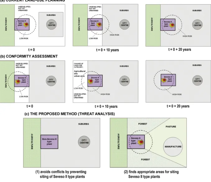
The approaches discussed above are either procedures involving evaluation of the conformity assessment of existing urbanisation with selected risk criteria (ex-post evaluation), or are applied during the licensing process for new developments (ex-ante eval-uation). In both cases a land-use plan is already available, so risk assessment is not involved in the plan preparation process; it is, rather, a basis for compliance assessment with the plan. The LUP issues in this regard are presented schematically inFig. 1. The figure also shows the ultimate aim of the threat analysis for solving the risk related LUP issues.
Part (a) ofFig. 1illustrates current situations: 10 or 20 years after the plan approval, and due to urbanisation development in the surroundings of the industrial zone where a Seveso II plant is situated, the situation is no longer satisfactory or acceptable (high risk) as it was at the time of plan adoption (att= 0). Possible LUP safety (risk) improvement measures are: relocation or shut down of the Seveso II plant; movement of the population from the residen-tial objects in proximity to the plant if the risk situation is extreme; implementation of additional preventive measures at the plant (e.g. safety improvement by installing additional safety device) as well as more effective protective measures in the surroundings (e.g. additional technical barriers against direct exposure of the popu-lation or improvement of the external emergency plan by assuring
effective evacuation). Part (b) ofFig. 1illustrates how the confor-mity assessment is to be understood. Such an assessment att= 0, i.e. at the time of adopting a plan may show that the situation in terms of risk is acceptable (low risk). However, if the conformity assessment is done again after 10 or 20 years, the result may no longer be satisfactory or acceptable. This would mean that only the “frozen” land-use state, as shown att= 0, assures conformity and low risk. If such a “freezing” of the current state of a land-use plan would indeed be applied it would fundamentally change the exist-ing philosophy and practice of land-use plannexist-ing. It would basically countermand what the plan (the society) was initially saying should happen as land-use development in the future, so a question about the very purpose of the land-use planning would arise. Part (c) of
Fig. 1illustrates the aims of threat analysis for ensuring either that no Seveso II plants are allocated in industrial zones surrounded by urban or other vulnerable areas (e.g. surface and groundwater for drinking purposes, natural protected areas, etc.), or that specific and clear conditions for siting hazardous installations are provided in the initial stages of preparing a land-use plan, so that risk conflicts are avoided during the whole timeframe of implementing the plan. Description and the illustration of the threat analysis are pro-vided in the following sections using the example of renewal of a land-use plan for the Municipality of Koper, Slovenia. The Seveso II plant is an LPG loading/unloading and storage facility.
For the purpose of this article the selected terms refer to the following:
Hazard – a chemical or physical condition that has the potential for causing damage to life, health, property or environment. Most hazards are dormant or potential, with only a theoretical risk of harm, i.e. the situation has the potential to be hazardous, so no con-cretisation of people, property or environmental elements which can be harmed at a specific site is provided when speaking about hazard. A hazard is usually used to describe a potentially harmful situation, although not usually the event itself – once the event has started it is classified as an emergency or an incident[14,29,30]. Risk – a combination of the likelihood of occurrence and the mag-nitude of the unwanted consequences[5,14,29].
Threat – specific evaluation of potential harm/loss being inflicted on the actual targets [29,31]. The key difference between haz-ard and threat is that threat relates to known subjects/elements of the environment which may experience consequences. While hazard is the potential for causing harm, as stated above, the threat is a concrete/specific situation of subjects/elements of the environment being exposed to the hazard (the exposure pathway being clearly identified). The term has been selected to reflect the expected environmental consequences related to certain incident. Basically, the meaning of the term “threat analysis” is similar to the term “consequence analysis” in the framework of risk assess-ment, however without the consideration of probabilities and/or frequencies. So, the key difference between threat and risk is that threat does not specify likelihood of the consequences in question. The benefit of introducing threat into LUP is two-fold:
- A land-use plan, as a product, does not involve a notion of likelihood of using land, so risk does not seem an efficient basis for determining actual and neighbouring land uses (e.g. no matter the probability of an industrial accident a society does not allow/confirm/incorporate casualties in a land-use plan but rather deterministically decides about land uses in the surround-ings; nevertheless, probabilistic approach may effectively inform a decision about which type of land use seems to be most appro-priate).
- Environmental consequence consideration in the land-use plan enables specification of conditions for neighbouring land uses, as well as organisational and architectural conditions and solutions
for urbanisation (e.g. potential of an accident which requires an evacuation of citizens in the neighbourhood may guide the design of transport infrastructure; as stated above, explicit con-sideration of probability of casualties is not praxis in land-use planning).
Land-use planning – refers to the process of generation of land-use plans (elaboration of plans)[28]. The phase of plan implemen-tation (i.e. checking conformity in the approval process of the development proposals, licensing) is excluded from the under-standing of this term; see alsoFig. 4.
Environmental threat vulnerability is the state or characteris-tic of the environmental component which is the receptor of a negative change (effect) due to an accident involving hazardous materials[32,33]. It describes the level of susceptibility of the environmental component to being harmed due to an accident involving hazardous materials; or, inversely, the degree to which an environmental system, or a part of a system (a component), possesses resilience and resistance to the specific consequences of an accident[34]. For example, different buildings express different resistance levels (or vulnerability) to overpressure; or, not all rivers express the same level of self-purification after an incidental pol-lution event. Eventually, the environmental threat vulnerability is a measure (a yardstick) of sustainability of an environmental ele-ment/component when exposed to a specific accidental effect (e.g. this measure answers the question whether the salmon fish will survive the expected concentrations of a hazardous substance in a specific river section after an accidental spill). Environmental com-ponents include humans, natural ecosystems (fauna, flora), water, air, infrastructure (buildings), etc.
Spatial attractiveness – in the context of land-use planning the term attractiveness relates primarily to the economic efficiency (benefit) of a site where a development proposal is going to be realised, e.g. morphology of the terrain, availability of infrastruc-ture (roads, electricity, etc.), water, workforce, etc.
2. Methodology 2.1. General
The method introduces the threat index as a tool for dis-tinguishing between different consequences expected on actual environmental components. The consequences are presented in relation to a GIS unit. The numerical expression of a threat index represents different levels of threat. In its essence, the threat index builds on a consequence-based approach of risk assessment and combines it with the vulnerability of targets – receptors of conse-quences. As such, it requires the identification of accident scenarios with a consideration of the spatial distribution of physical effects. Accident scenarios are selected based on their relevance for land-use planning. This means that all scenarios having impact outside the plant limits, no matter the frequency, need to be considered. Such an approach does not exclude “low probability high conse-quence” situations (scenarios). It is adequate for two reasons: first, both possibility of an accident and the magnitude (scope) of its consequences are evaluated, and second, land-use planners and all parties in the process of plan approval get confidence that con-sideration of potential accidents was comprehensive and complete (contribution to trustworthiness and transparency of the overall LUP process).
2.2. Requirements of spatial planners for the methodology
In the process of conceptualisation and early design of the methodology, a number of workshops and discussions were
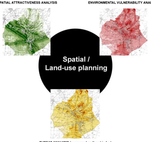
organ-Fig. 2.Introduction of threat analysis into the existing spatial suitability approach.
ised. Officials from the Municipality of Koper, representatives of Seveso II establishments located in the Municipality of Koper, land-use planners and risk assessors participated in these workshops. A summary of the discussions in terms of requirements for the methodology is included inAppendix A.
2.3. Description of the key features of the method 2.3.1. Threat index
Following the requirements for the methodology (seeAppendix A), the introduction of the threat index is designed as an additional, i.e. the third, component to the already existing spatial attrac-tiveness analysis and environmental vulnerability analysis of the spatial suitability approach in the framework of the Slovenian land-use process (Fig. 2). The main advantage of the approach is that it can provide preliminary guidelines for allocation of new hazardous establishments, and acts as a controlling instrument for develop-ment proposals around existing ones.
The approach of analysing and combining environmental vul-nerability and spatial attractiveness into spatial suitability has been in practice in Slovenia since the early 1990s[35–40]. The concept is that it is possible to evaluate how attractive a certain piece of land is for a particular activity, and how vulnerable is a particular environmental component on the very same piece of land to the particular impact of the same activity. By superimposing these two values we can obtain an evaluation which piece of land is better or worse for allocation of a particular activity. When making this analysis by means of GIS it is easy to geographically identify these better and worse sites. The approach is now standardised in the framework of LUP in Slovenia.
Threat analysis resulting in a definition of a threat index consists of the following steps (the process is schematically presented in
Fig. 3).
2.3.1.1. Step 1. Quantitative assessment of the outcomes of an inci-dent (e.g. fire, explosion, toxic cloud) and their physical effects (overpressure, thermal radiation, toxic concentrations in the air) is made by using standardised and widely accepted models[29,41], e.g. TNT, Baker–Strehlow for explosions, Pasquill–Gifford model (Gaussian dispersion) for dispersion in the air. In addition to these, threat analysis also involves, based on the accident scenario, quantification of toxic concentrations in water for the purpose of evaluation consequences for both water biota and humans (e.g. loss of drinking water source). Different dispersion models could be used for these quantifications, e.g. Stream model[42]. This step is the initiating step of consequence estimation and represents the incident outcomes obtained by scenario analysis, associated with the impact on the surroundings that could develop from a certain incident of interest. These outcomes serve as a basis for determining the threat intensity level of an incident in the following step.
2.3.1.2. Step 2. Threat intensity levelis a measure oriented to repre-senting the magnitude and spatial distribution of the consequences associated with selected physical effects of incident outcomes
(overpressure, thermal radiation, toxic concentrations in air and water). It takes into account a set of threshold levels concerning these consequences. In its core it is conceptually similar to risk severity[43–45]. The threat intensity is presented as a series of GIS based maps for selected physical effects, where each cell carries a value on a scale of 1–5 according to threshold level (1 – low, 5 – high), based on e.g. TEEL or ERPG values for the evaluation of threat intensity to humans, or concentration levels with dose assessment (e.g. LC50or LD50for fish for the evaluation of threat intensity to
a river’s or lake’s biota). One should note that measures like Pro-bit model results are not applicable in the LUP process, since they describe human death probability (expectation of human death from industrial accidents is not applied in land-use planning, due primarily to ethical and equity reasons). Probit model results other than zero, if attempted to be applied in land-use planning, would most probably lead to strong societal disagreements and conflicts, with the eventual result of not approving a plan, in spite of the acci-dental context of the issue. On the other hand TEEL and ERPG values constitute a common basis for emergency planning.
2.3.1.3. Step 3. Environmental threat vulnerability analysisof poten-tial receptors (humans, natural resources, built environment) located in the vicinity of hazardous industrial establishments. Envi-ronmental threat vulnerability, as used in this method, is defined in the introduction. Compared to environmental vulnerability defined in the ARAMIS project[43], the environmental threat vulnerability proposed in this paper answers not only the question which ele-ment is more precious to us, i.e. the question of weights assigned to the vulnerability of humans, material values and nature, but also whether the environmental element of interest will withstand the threat intensity level it is going to be exposed to in the case of an accident.
The environmental threat vulnerability is expressed as a ratio of the expected environmental damage/loss to the maximum pos-sible damage/loss on a scale of 0–100%, translated into a scale of 1–5. The scale is based on pre-set criteria for exposure and received amount of energy/mass, i.e. dose, taking into account the probability whether the actual environmental element will with-stand this dose (1 – no effects, 2 – negligible effects, 3 – reversible effects, 4 – irreversible effects, 5 – destruction/loss). This proba-bility assessment is derived as expert opinion, taking into account, e.g. construction quality standards, building and architectural codes of practice, information on the sensitivity of specific population groups, etc. Presentation of the vulnerability is then provided for each grid cell.
The thresholds may also consider passive and active protective measures designed by municipal policies or experience of particu-lar sectors, such as the sector for civil protection and rescue. In the case that no specific thresholds are provided, the ones presented in
Table 1could be used.
The result of environmental threat vulnerability analysis is a series of GIS based maps for selected environmental elements and certain physical effects of an incident. When combined with threat intensity level maps, threat index maps are produced, see Step 4.
Table 1
Thresholds to be applied in environmental threat vulnerability analysis[46–49] Environmental threat vulnerability – reference values
Damage/loss level Effects Overpressure (kPa)[46,47] Thermal radiation (kW/m2)[48] Toxic release to air[49]
1 – Low No effects <2.1 <4.5 <TEEL 1 <ERPG 1
2 – Low to medium Negligible effects 2.1–6.9 4.5–12.5 TEEL 1 ERPG 1
3 – Medium Reversible effects 6.9–13.8 12.5–25 TEEL 2 ERPG 2
4 – Medium to high Irreversible effects 13.8–20.7 25–37.5 TEEL 3 ERPG 3
Table 2
Combinations of threat intensity level and environmental threat vulnerability as a basis for the determination of threat index
Environmental threat vulnerability level
Threat intensity level
1 2 3 4 5 1 1 1 2 3 4 2 1 2 3 3 4 3 2 3 3 4 4 4 3 3 4 4 5 5 3 4 4 5 5
Note: Each value is assigned to a specific GIS grid cell in the area under consideration. The product of this assignment is a threat index map.
2.3.1.4. Step 4. Threat indexexpresses the degree of threat to a spe-cific environmental element in the case of an accident.
The index has values ranging from 1 to 5 which are established by combining values on a 1–5 scale for both threat intensity level and environmental threat vulnerability. The combinations are pre-sented inTable 2. The table is similar to an ordinary risk matrix which combines the frequency/probability of an accident and the severity of its consequences.
A threat index map may serve as a support in the process of revising the land-use plan around existing hazardous installations and as a guideline for developing a new plan or finding a suitable location for a proposed development project. If there are site alter-natives for allocating hazardous industrial installation, threat index results could be used to evaluate which alternative would cause the least threat.
The threat index map also represents the basis for argumented discussion with those who live, work and/or place values in the affected area, and have, therefore, the right to be included in the final determination of the use of land, according to physical plan-ning legislation in Slovenia[50].
2.3.2. Possible developments of the LUP process in Slovenia in terms of involving threat analysis
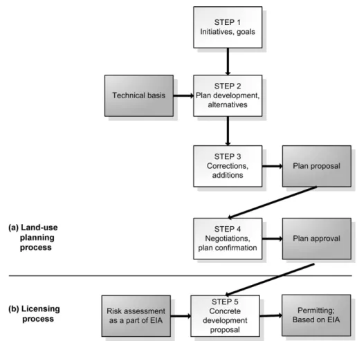
The existing land-use planning process in Slovenia is schemat-ically presented in Fig. 4. It consists of four main steps. It is evident that neither hazard, threat nor risk analysis/assessment are involved in this process. However, risk assessment is required in the implementation stage – step 5 – as a part of the environmen-tal impact assessment (EIA) process during the licensing procedure
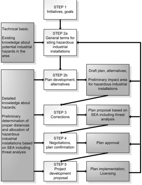
[50,51]. Such an approach is not in accordance with the Seveso II Directive which requires consideration of risk assessment results in the LUP process as a means of minimising the consequences of accidents. A suggested improvement of the planning process so as to meet this requirement is presented inFig. 5. It divides step 2 into two sub-steps, extends the technical basis by general terms for siting of hazardous installations, provides preliminary determina-tion of appropriate distances between a hazardous installadetermina-tion and vulnerable surrounding land uses, and introduces strategic envi-ronmental assessment (SEA) as a tool for identifying the best plan alternative also in terms of threat. In addition, it requires contin-uous monitoring of the plan implementation (loop from step 5 to sub-steps 2a, 2b, 3, and 4). Such a feedback enables prevention of conflicting spatial development around hazardous installations by means of maintaining proper distances as long as needed.
Fig. 5.Schematic representation of the proposed land-use planning process in Slovenia.
3. Illustration of the methodology – LPG storage facility and the renewal of the land-use plan for the Municipal plan of Koper
3.1. General
Municipality of Koper is located in a south-western part of Slove-nia, and is covering a majority of Slovenian coastal area. The main economic activities in the municipality are tourism, agriculture and industry.
The town of Koper has approximately 25 000 inhabitants. The average population density is 155 persons/km2.
The characteristic landscape around the LPG storage facility is agricultural land, formerly salty marsh, dried out through history.
Fig. 6 shows a section of the existing land-use plan for the Municipality of Koper around the LPG storage facility – a Seveso II establishment, which was used as a case study for illustrating the methodology. The land-use plan is currently under the renewal process.
3.2. LPG storage and handling facility
The LPG storage and handling facility is an upper tier Seveso II establishment, located in the industrial/commercial zone to the north-east of the town of Koper.
The operations include:
- Loading, unloading and storage of LPG; total storage capacity is 450 m3in three 150 m3vessels.
- Filling of LPG into 10 kg steel containers for households. - Distribution of LPG for industry by road tankers and 10 kg steel
containers to households.
Adjacent to the facility three manufacturing organisations employ-ing approximately 120 persons are located. The nearest residential area is 150 m north of the site.
South-west at a distance of approximately 400 m from the estab-lishment, a salty shallow lake is situated (formerly sea) and is categorised as a special environmentally protected area – Natura 2000 site[52]. South-east, at a distance of 500 m, the protected tree line is located.
Based on the findings of formal safety report[53]and subse-quent discussion with the author of the report and managers of the establishment, the following scenarios are considered as relevant for LUP (a consequence-based approach used for the selection of scenarios, see also Section2.1):
(a) Boiling liquid expanding vapour explosion (BLEVE) of the 150 m3storage vessel.
(b) Vapour cloud explosion (VCE) after a spill of LPG during load-ing/unloading of road tankers due to a break (failure) of a flexible hose.
Small leakages from standard 10 kg steel containers of LPG are not classified as relevant for LUP consideration.
Scenario (b) is treated both as an independent scenario, as well as an initiating situation for the development of scenario (a). In the latter, VCE causes damage to valves and connecting piping of the adjacent 150 m3storage vessel, as well as to a fixed fire
extinguish-ing/cooling system at the loading/unloading and storage area, with additional major release of LPG leading to a major fire and the final event of a BLEVE of one of the 150 m3vessels[14,53]. The safety
report and analysis conclude that a jet-fire at the end of the broken flexible hose or damaged fixed piping could not cause BLEVE, since direct impingement is excluded due to the parallel position of the vessels and the road tanker (with a maximum 5 m long hose) at the loading/unloading facility, the position of piping below the vessel, and the low hydrostatic pressure of LPG in the damaged piping. The primary consideration of the scenario in the safety report is therefore the initial spill of LPG. After explosion of a vapour cloud a fire occurs at the loading/unloading and storage area due to major release as a consequence of the damage to the installation caused by VCE. This major fire causes BLEVE of one of the two undamaged ves-sels. The possibility of two simultaneous BLEVE was excluded due to the intensive evaporation of the spilled LPG, and the solid sepa-ration walls between the vessels which prevented spilled LPG from flowing and formed a fire under both the vessels, while a domino effect (one BLEVE at a time) would have an almost identical impact area as a single one. Also, additional damage in the surroundings due to a second BLEVE would be of less importance than the first one.
The source of ignition of the vapour cloud is assumed to be at a distance of 50 m (the distance to the facility boundary where ignition sources are not controlled).
The BLEVE scenario assumes that the LPG is partly exploded, partly burned and partly evaporated and dispersed. The analysis was made for 72 tonnes of LPG[53](maximum vessel capacity – conservative approach) and 36 tonnes (half vessel capacity – rea-sonable approach). The modelling calculations were made using PHAST v6.1 software[53].
3.2.1. Threat analysis for overpressure
3.2.1.1. Threat intensity level. The results of the threat intensity level for overpressure for the BLEVE scenario are summarised inTable 3
and presented inFig. 7.
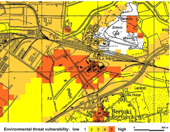
3.2.1.2. Environmental threat vulnerability. The results of the envi-ronmental threat vulnerability analysis for overpressure in the vicinity of the LPG storage facility are presented inFig. 8.
The highest levels of vulnerability are observed in indus-trial/commercial, residential (possibility of injuries, material damage) and protected natural areas.
3.2.1.3. Threat index. Threat index maps are presented inFig. 9; the key for the determination is presented inTable 2.
Both figures show the highest levels of threat (categories 4 and 5) within the industrial/commercial area, posing a threat to several neighbouring facilities/buildings. Note that threat indices are presented up to the distances determined by the threat intensity levels; beyond these distances no threat indices are
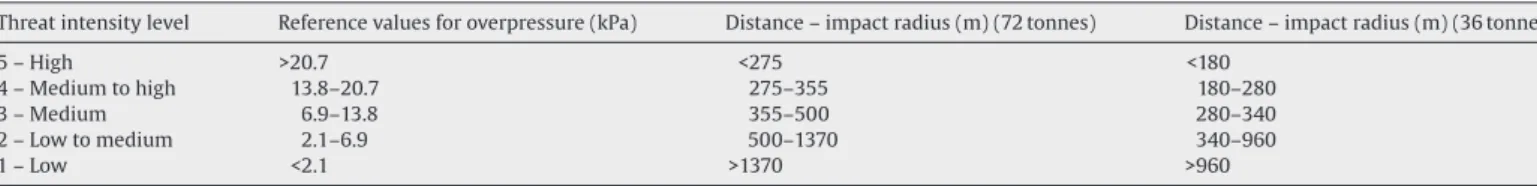
indi-Table 3
Threat intensity level for overpressure for BLEVE scenario of 150 m3LPG vessel
Threat intensity level Reference values for overpressure (kPa) Distance – impact radius (m) (72 tonnes) Distance – impact radius (m) (36 tonnes)
5 – High >20.7 <275 <180
4 – Medium to high 13.8–20.7 275–355 180–280
3 – Medium 6.9–13.8 355–500 280–340
2 – Low to medium 2.1–6.9 500–1370 340–960
Fig. 7.Threat intensity level for overpressure – conservative approach 72 tonnes (a) and reasonable approach 36 tonnes (b).
cated, no matter how vulnerable environmental components may be.
3.2.2. Threat analysis for thermal radiation
3.2.2.1. Threat intensity level. The results of the threat intensity analysis for the thermal radiation scenario are analogous to the ones for overpressure and are summarised inTable 4.
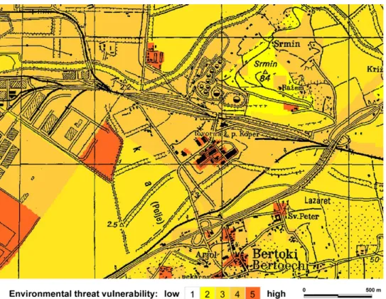
3.2.2.2. Environmental threat vulnerability. An environmental threat vulnerability analysis for thermal radiation was made similar to the analysis for overpressure. The results are presented inFig. 10.
Again, the highest levels of vulnerability were observed in industrial/commercial, residential, agricultural and natural areas.
Fig. 8.Environmental threat vulnerability for overpressure in the vicinity of the LPG storage facility.
3.2.2.3. Threat index. Threat index maps are presented inFig. 11. The results are similar to those for overpressure, only distances in the conservative approach are smaller.
3.2.3. Threat reduction measures
Based on the results of threat analysis, the proposed threat reduction measures are:
(a) Replacement of the flexible hose with a mechanical arm. By replacing the flexible hose with a mechanical arm, the pos-sibility of an initiating event, i.e. a spill as a result of a hose failure during loading/unloading of road tankers is eliminated. The decoupling mechanism of the mechanical arm allows the release of only 0.1 l of LPG[53,54]. This measure eliminates both the VCE and the BLEVE scenario.
(b) Burial of the 150 m3LPG vessels, i.e. underground storage. Such
a technological change would eliminate the BLEVE scenario, but it is more expensive than the installation of a mechanical arm. In addition, the VCE scenario still remains as possible.
(c) Guiding future land-development away from the risk source. This approach is less favoured by establishment managers, since certain areas potentially suitable for development are left unused, functioning as safety buffer zones. Management of such buffer zones is usually the responsibility of the authorities; however, costs for maintaining the zone are covered by the risk source.
In the context of both economic and risk considerations, the most reasonable option is option (a). Option (b) is significantly more expensive in terms of investment expenditures than option (a), while option (c) is basically a prolongation of the existing situation that is not desirable (tolerable) any longer, either by the Municipal-ity of Koper or by other users/owners of land in the buffer zones. Further, the risk reduction of the three measures is not the same. Option (a) provides most efficient risk reduction, since it elimi-nates both VCE and the BLEVE scenario. Option (b) is less effective than option (a), since it eliminates BLEVE scenario but not the VCE. Option (c) does not prevent either the VCE or the BLEVE scenario, but is effective in terms of risk reduction and elimination of the consequences in the surroundings by guided land use and establish-ment of the buffer zone. Taking into account these characteristics, managers of the LPG establishment selected option (a).
3.3. Results in terms of possible changes to the land-use plan of the Municipality of Koper
The existing situation without implementation of the threat reduction measures (a and b) requires in the context of LUP a formal safety buffer zone around the LPG facility (threat reduction measure c), seeFig. 12. So far, such a zone has not been formally established, however no urbanisation was allowed around the plant, only agri-cultural activities. If the buffer zone were to be established, it would be under constant development monitoring, where no
develop-Table 4
Threat intensity level for thermal radiation for BLEVE scenario of 150 m3LPG vessel
Threat intensity level Reference values for thermal radiation (kW/m2) Distance – impact radius (m) (72 tonnes) Distance – impact radius (m) (36 tonnes)
5 – High >37.5 <210 <160
4 – Medium to high 25–37.5 210–250 160–190
3 – Medium 12.5–25 250–370 190–290
2 – Low to medium 4.5–12.5 370–650 290–500
Fig. 9.Threat index for overpressure – conservative approach 72 tonnes (a) and reasonable approach 36 tonnes (b).
ment would be encouraged. Location, construction and operational permits at larger distances than the buffer zone radius would be a question of case-by-case considerations by the authorities.
On the other hand, if either of the other two threat reduction measures were applied – measures (a) and (b) – the consequent reduction of the impact area could make future uses of the
sur-roundings more liberal and oriented towards stronger economic development. Possible changes in that context are presented in
Fig. 13and inTables 5–7. This simulation was a basis for devel-oping a number of LUP alternatives for this area in the ongoing process of renewal of the municipal plan. Outcome based on specific economic studies, discussions and negotiations among potential
Fig. 10.Environmental threat vulnerability for thermal radiation in the vicinity of the LPG storage facility.
Table 5
Current property values in Koper region
Land use Price (D/m2)
Agriculture, pastures 8
Vineyards/olive groves 30
Development plots 150
Individual housing (U1) 700
Blocks of flats P/4 (U2) 3500
Commercial (U3) 1000
investors (future land users) is pending; SEA is to be performed to help identifying the best alternative; agreement and approval of the renewed plan is expected by the end of the year.
4. Discussion
Testing of the methodology revealed several important topics which require attention and discussion. These are summarised as follows:
(a) The role of accident scenarios for the determination of impact area.
Table 7
Land value gain after BLEVE scenario elimination
Land use Area (ha) Price (D/m2) Value (MD)
Agriculture, pastures 10 8 0.8
Individual housing (U1)a 6 700 16.8
Commercial (U3)a 3 1000 12.0
Sum 29.6
aU1 and U3 categories take into consideration urbanisation density factor of 0.4.
One should be aware of the implications of the accident sce-narios at two levels. The first is selection of a scenario which has an impact on land-use planning. It is obvious that for this purpose some kind of preliminary threat or risk analy-sis should be made first, providing a geographical indication of the scope of the consequences before detailed threat anal-ysis is performed. In land-use planning impacts of the scenario are relevant in terms of both human interests for land use and environmental protection. How much land a certain accident scenario “covers” (i.e. how big is the impact zone) and what environmental qualities may be degraded or lost in the case of an accident is ultimately a question of acceptability. Whether or not accident scenarios clearly and adequately consider and
asso-Table 6
Implication of the BLEVE scenario – realistic approach (36 tonnes) on land value loss due to no land development; selected categories of thermal radiation and overpressure Values of land according to different uses based onTable 5(MD)
Physical effect – selected reference values
Distance to selected reference values (m)
Area associated to reference values and distances (ha)
Agriculture/fields, pastures Vineyards/olive groves U1a U2a U3a BLEVE 36 tonnes 12.5 kW/m2 290 22.4 1.8 6.7 62.8 314.0 89.7 37.5 kW/m2 160 5.0 0.4 1.5 14.0 70.1 20.0 13.8 kPa 280 20.7 1.7 6.2 57.9 290.0 82.8
Fig. 11.Threat index for thermal radiation – conservative approach 72 tonnes (a) and reasonable approach 36 tonnes (b).
ciate these issues is a question to be identified during the LUP process.
The second level is accuracy or rather the trustworthiness of the scenario. If the uncertainty of the selected scenario is too big and subsequent alteration of the impact area too signifi-cant, the land-use planning process may reject the approach as too vague, or too sensitive, or non-robust. Namely, specific
land uses in an actual land-use plan have sharp and static bor-ders; there are no “grey” zones between neighbouring land uses, which would, for example, imply uncertainties of the accident scenario (e.g. alteration of the impact zone due to different mod-elling assumptions causing variations of the amount of released toxic gas). If scenario uncertainties are so big that they affect LUP process additional efforts should be made either to identify
Fig. 12.Possible changes of the land-use plan around the LPG facility: (a) establishment of the formal safety buffer zone if no threat reduction measures are implemented at the facility, (b) possibility of different urbanisation after replacing flexible hose with a mechanical arm – see details inFig. 13.
their sources, classify them into categories (e.g. epistemic or sta-tistical) and find the means for their reduction, or to investigate what additional safety measures could be applied (improve-ment of the SMS at the plant) for the elimination of the scenario or diverting it into one with lower uncertainty, or to the one non-relevant for LUP.
To illustrate possible influence of modelling uncertainty,
Tables 3 and 6are merged intoTable 8; the difference in impact areas for selected reference values is approximately within fac-tors 1.6–2.1, when applying a conservative or realistic approach (different assumptions) to scenario analysis.
(b) Economic implications of threat analysis in the framework of LUP.
The expected financial loss or gain due to establishing buffer zones in the impact area (no development) or allowing land development (housing, commercial zone) may be considerable (Tables 5–7). Presentation of such results in a transparent way may support the land-use planning process as a vehicle for enforcing threat/risk reduction measures at certain
installa-tions. Actually, this has been the case in the Municipality of Koper; in the stage of reviewing the land-use plan, the Munici-pality, i.e. the local authority, required the managers of the LPG establishment to reduce impact area by applying either mea-sure (a) or (b), see Section3.2.3. As stated above, the managers of the LPG facility decided to install a mechanical arm at the loading/unloading facility, which is the most reasonable option (most benefits for least cost).
(c) Application of the method for new hazardous installations. The method is designed to contribute to land-use manage-ment around existing hazardous installations, as well as to inform the search for suitable locations for new ones and to be used when preparing a new land-use plan. However, there are a number of issues related to the latter. The main problem here is a lack of information about new installations (technology, capacity, safety measures) in the early land-use planning phases. The solution for the LUP process in Slovenia is being sought in an additional methodological step in land-use plan devel-opment, as well as revision (amendment) of existing steps (see
Fig. 13.Illustration of possible land development scenario after elimination of the BLEVE scenario. Explanation of U1 and U3 is inTable 5.
Figs. 4 and 5). The main idea is that through strategic environ-mental assessment (e.g. assessment of alternatives of a land-use plan) the general terms and conditions for allocation of haz-ardous installations are provided, while in the following steps a precise siting process is applied along with the determina-tion of appropriate distances, orientadetermina-tion, eventual buffer zones and use of land in the vicinity of the establishment – based on more specific information provided by the investors. In this phase guidelines for urban (traffic routes, allocation of vulnera-ble buildings – hospitals, schools, etc.) and architectural design would also be provided, with the goal of assuring the efficiency of emergency response, if needed. Application of the suggested guidelines, terms, and conditions would be realised in combined and harmonised processes of land-use planning, strategic envi-ronmental assessment and finally project level envienvi-ronmental impact assessment.
(d) Relation between risk assessment and threat analysis.
It is obvious that common risk assessment results could be efficiently used in threat analysis and vice-versa. The out-come in both cases is upgrading of the methods and improved land-use plans. No matter where the analysis starts, e.g. from consequence analysis in the framework of risk assessment through environmental vulnerability to threat index, or from environmental threat vulnerability through accident scenario
consequence analysis to threat index, the LUP process will gain a solid scientific basis for achieving long-term stable agreement among the stakeholders involved regarding uses of land around a hazardous installation. Nowadays, at least in Slovenia, no risk assessment or threat analysis for hazardous industry is formally applied at the level of land-use planning.
(e) Changes of safety management system.
Also relevant in terms of determining the scope of impact areas of the scenario are the factors of the safety management system (SMS) of the facility. These have also been addressed by the proposed method, however SMS can be changed within a short time period, while general land-use plans are made for longer time periods (10 or 20 years or even longer). In the case where violation of conformity with the land-use plan regard-ing safety is recognised, the responsible inspector (SMS is the subject of regular safety auditing and inspection) is obliged to require improvements for the purpose of harmonising the SMS and overall safety of the installation with the LUP. The need for continuous development monitoring around hazardous indus-trial installations is thereby evident.
(f) Who should make the threat analysis: risk assessors or land-use planners?
Our example showed that common scope and form of risk assessment results as provided in the formal safety report[53]
Table 8
Implication of the scenario uncertainty to the scope of impact area
Physical effect – selected reference values Distance to selected reference values (m) Impact area (ha) Difference in impact area; ratio between conservative/realistic approach
BLEVE 36 tonnes BLEVE 72 tonnes BLEVE 36 tonnes BLEVE 72 tonnes
12.5 kW/m2 290 370 22.4 37.6 1.7
37.5 kW/m2 160 210 5.0 10.4 2.1
were not sufficient in the process of renewal of the land-use plan. Consequently, one of the key questions was who is going to upgrade the results, i.e. who will perform the work repre-sented by arrows inFig. 3and produce related GIS based maps with their proper interpretation for the purpose of the approval of the renewed land-use plan: risk assessors or land-use plan-ners? The answer is, based on our experience, that this work could be properly done only within strong and continuous col-laboration between the two groups of experts. This means that risk assessors should not just “throw their own results over the fence” to the land-use planners (i.e. just submit a safety report), thus trying to get back to their next risk assessment work as soon as possible. The collaboration should be maintained until the land-use plan in question is approved! Such a collaborative culture among risk assessors and land-use planners has still to be developed in Slovenia; we assume that a similar need can be found elsewhere.
The praxis of the implementation of the threat index will show how effectively Slovenia succeeded in avoiding such situations and conflicting developments as are presented inFig. 1a and b. In this context it is important to note that the threat index approach is applicable not only for avoiding conflicts between industrial zones and outer land users but also land users in the industrial zones themselves. One of the examples of such applications is the alloca-tion of process and other plants (e.g. storage facilities) in a way that prevents domino effects. The other could be a design and
organi-sation of the whole industrial zone that stresses vulnerability and importance of the common infrastructure in the zone, e.g. fire fight-ing installations or coolfight-ing water network needed for two or more plants/processes in the zone. Application of the threat analysis early enough in the design process is certainly in line with the preven-tive strategy of risk assessment and a good safety management system.
5. Conclusions
Threat analysis for hazardous industrial installations, as an approach to threat-informed land-use planning, enables trans-parent and understandable interpretation of threat for land-use planning purposes. It successfully combines consequence anal-ysis results of quantitative risk assessment with environmental vulnerability analysis. As such the method presents a way of imple-mentation of Article 12 of the Seveso II Directive. It can be used as an additional scientific basis for siting new hazardous industrial installations.
The results of our study also show the specific economic bene-fits of the approach in the Municipality of Koper. After testing the method on several other cases, its potential for general use will be assessed.
Appendix A. The requirements of spatial planners for the methodology and responses to these requirements
Phase Description Basic requirements Responses to requirements and
novelties
Phase 1: Conceptualisation
This step introduces threat index. The threat index converts classical hazard and risk assessment results into a form which is applicable in the process of land-use planning.
Maintaining current philosophy and practice of land-use planning; threat index should be directly applicable.
Legal and philosophical framework (current practice) for land-use planning remains as it is. In that context zoning policy/approach provides background for approval of spatial suitability for certain land use.
The same profiles of expertise are involved in the planning process (e.g. sectoral planning, infrastructural planning, landscape architecture, urban planning, architecture, civil
engineering); an additional expertise is industrial accidental risk assessment. Applying/maintaining
approach of spatial suitability for development projects.
The combination of environmental vulnerability with spatial attractiveness analysis is the basis for determining spatial suitability. This approach is well known, well understood and widely accepted among stakeholders in Slovenia. The introduction of threat analysis into the land-use planning process does not change this approach, but follows it as much as possible. See Fig. 2.
Holistic approach to environmental impacts.
Standard risk assessment usually focuses on consequences to humans. Threat analysis takes into consideration the environment holistically and addresses, besides humans, also nature, natural resources and the built environment, since they are all categories encompassed by the land-use planning process.
Applying GIS tools. Application of GIS tools is common, widely used and standardised.
Appendix A (Continued)
Phase Description Basic requirements Responses to requirements and
novelties Consideration of the need for
small impact zones.
Each accident has its specific impact zone. Reduction and optimisation of the extent of impact zones is provided by means of accidental scenario analysis and enforced by the relevant technical and organisational measures at the installation for the purpose of limiting releases or reducing the likelihood of occurrence, or both.
Associated with siting new installations small impact zones are imperative in the first place. In that sense the land-use planning process is recognised as a mechanism for enforcing technological optimisation for the purpose of reducing impact zones as much as possible.
Phase 2: Implementation design
Implementation should encompass environmental modeling and should allow qualitative and quantitative determination of threat in designated area.
Differentiation between existing and new installations; existing installations should be able to adapt to identified threat while the new ones should maintain conformity by continuous monitoring of land developments of neighbouring land use.
The method should differentiate between existing and new installations. For existing installations the technology, safety management systems (SMS), operational records, compliance status, standardisation etc. is known. Therefore, determination of impact zones for particular accident is relatively accurate. On the other hand, at the stage of preparation of a land-use plan for a new industrial zone, this information is not available. In such cases determination of impact zones is uncertain, so the method should reflect this issue. At the moment the method is tested for existing installations only.
Regular auditing of SMS contributes to overall (safety) compliance assessment, which is a basis for prolongation of the operational permit of the establishment every five years. If violations of safety standards/expectations are recognised during the auditing, the inspector is obliged to decide whether to stop of the operation of the establishment or particular facility.
Interpretation and
presentation of threat analysis results for land-use planning purposes.
Commonly risk assessment results are presented in the form of probability for a certain accident consequence. Sometimes the extent and spatial distribution of these consequences are given. For LUP purposes spatial interpretation and presentation of risk consequences is the only form which is beneficial. In that context threat analysis end-points (expressed as threat index) are formulated accordingly.
Transparency of the presentation of threat indices by means of GIS tools.
In the process of combining
environmental vulnerability with spatial attractiveness into spatial suitability, each cell of a GIS grid has a particular value. These values are transparent, retrievable and justifiable. The same applies for threat, where threat index is assigned to each cell of the grid in the impact zone.
The threat index combines
environmental threat vulnerability and the threat intensity level.
Phase 3: Testing and approval Testing should be done by means of a case study within revision of the land-use plan.
The method should be tested at the municipal level.
The method should be tested by means of a case study. The testing procedure should be clear and understandable for public participation purposes. The municipality of Koper and an LPG storage facility were selected as a case study.
References
[1] M.D. Christou, Implementation of Seveso II Directive, in: C. Kirchsteiger, M.D. Christou, G.A. Papadakis (Eds.), Risk Assessment and Management in the Con-text of the Seveso II Directive, Industrial Safety Series 6, Elsevier, Oxford, 1998, pp. 437–446.
[2] M.D. Christou, A. Amendola, M. Smeder, The control of major accident hazards: the land-use planning issue, J. Hazard. Mater. 65 (1999) 151–178.
[3] M.D. Christou, M. Mattarelli, Land-use planning in the vicinity of chemical sites: risk-informed decision making at a local community level, J. Hazard. Mater. 78 (2000) 191–222.
[4] I.A. Papazoglou, G. Bonanos, H. Briassoulis, Risk informed decision making in land use planning, J. Risk Res. 1 (2000) 69–92.
[5] European Commission, Seveso II Directive – Council Directive 96/82/EC of 9 December 1996 on the control of Major Accident Hazards Involving Dangerous Substances.
[6] European Commission, Directive 2003/105/EC of the European Parliament and of the Council of 16 December 2003 amending Council Directive 96/82/EC on the control of major-accident hazards involving dangerous substances, Official Journal L 345, 31/12/2003 P. 0097-0105, 2003.
[7] M. Smeder, M.D. Christou, S. Besi, Land use planning in the context of major accident hazards – an analysis of procedures and criteria in selected EU member states, Report EUR 16452 EN, Institute for Systems, Informatics and Safety, JRC Ispra, Ispra, 1996.
[8] B. Rasmussen, I. Bertelsen, V. Burchard, P. Christensen, N.J. Duijm, C.D. Groen-berg, F. Markert, Multi-Objective Decisions in Land Use Planning Involving Chemical Sites, Risoe National Laboratory, Roskilde, 1999.
[9] G. Spadoni, D. Egidi, S. Contini, Through ARIPAR-GIS the quantified area risk analysis supports land-use planning activities, J. Hazard. Mater. 71 (2000) 423–437.
[10] U. Hauptmanns, A risk-based approach to land-use planning, J. Hazard. Mater. 125 (2005) 1–9.
[11] C. Basta, M. Struckl, Implementing Art. 12 of the Seveso II Directive: overview of procedures in selected member states & »Roadmap« proposals – draft version, European working group on Land-use planning, The Joint Research Centre of the European Commission, 2005.
[12] D. Konti ´c, B. Konti ´c, M. Gerbec, How powerful is ARAMIS methodology in solv-ing land-use issues associated with industry based environmental and health risks? J. Hazard. Mater. 130 (2006) 271–275.
[13] V. Cozzani, R. Bandini, C. Basta, M.D. Christou, Application of land-use planning criteria for the control of major accident hazards: a case-study, J. Hazard. Mater. 136 (2006) 170–180.
[14] AICHE CCPS, The Guidelines for Chemical Process Quantitative Risk Assessment, American Institute of Chemical Engineers, New York, 1989.
[15] AICHE CCPS, The Guidelines for Hazard Evaluation Procedures, American Insti-tute of Chemical Engineers, New York, 1989.
[16] T. Kletz, Hazop, Hazan, Identifying and Assessing Process Industry Hazards, third ed., Institution of Chemical Engineers, Warwickshire, 1992.
[17] Health and Safety Executive (HSE), Risk Criteria for Land Use Planning in the Vicinity of Major Industrial Hazards, HMSO, London, 1989.
[18] Health and Safety Executive (HSE), The Buncefield Investigation: Progress Report, London, 2006.
[19] G.M.H. Laheij, J.G. Post, B.J.M. Ale, Standard methods for land-use planning to determine the effects on societal risk, J. Hazard. Mater. 71 (2000) 269–282. [20] C. Basta, J.M.M. Neuvel, S. Zlatanova, B. Ale, Risk-maps informing land-use
plan-ning processes; a survey on the Netherlands and the United Kingdom recent developments, J. Hazard. Mater. 145 (2007) 241–249.
[21] M.L. Stangl, Land Use Planning in the context of Seveso II establishments in Austria, in: Presented at SRA-E 2006 Conference, Ljubljana, Slovenia, 11–13 September, 2006.
[22] S. Besi, F. Amendola, V. Belloni, M.D. Christou, M. Smeder, A. Amendola, U. Poli, La pianificazione dell’uso del territorio in relazione ai rischi di incidente rile-vante, Report EUR 16412 IT, Institute for Systems, Informatics and Safety, JRC Ispra, Ispra, 1996.
[23] Le plan de préventiondes risques technologiques (PPRT) – Guide méthodologique, Ministère de l’écologie, du développementet de l’aménagement durables, Direction de la Préventiondes Pollutions et des Risques, Direction Générale de l’Urbanismede l’Habitat et de la Construction, Republique Francaise, http://www.ecologie.gouv.fr/Les-Plans-de-Prevention-des.html(accessed on 23 April 2008).
[24] N. Dechy, The Toulouse disaster 21st September 2001: Global lessons learnt and Risk Management changes, presented at the Risk Forum at Enterprise LSE, Annual Conference London, 9 June 2006, available at http://www.terf.org.uk/?m=200606(accessed on 30 April 2008).
[25] Ministerial Decree of 9 May 2001, Requisiti minimi di sicurezza in materia di pianificazione urbanistica e territoriale per le zone interessate da stabilimenti a rischio di incidente rilevante, Gazzetta Ufficiale della Repubblica Italiana, no. 138, Rome, 16 June 2001.
[26] A. Carpignano, G. Pignatta, G. Spaziante, Land use planning around Seveso-II installations: the Italian approach, in: Proceedings of the European Conference on Safety and Reliability, MG, Torino, 2001, p. 1763.
[27] M.D. Christou, S. Porter, Guidance on land use planning as required by Council Directive 96/82/EC (Seveso II), Institute for Systems, Informatics and Safety, Ispra, 1999.
[28] M.D. Christou, M. Struckl, T. Bermann, Land-use Planning Guidelines in the context of Article 12 of the Seveso II Directive 96/82/EC as amended by Direc-tive 105/2003/EC, European Commission, Joint Research Centre, Major Accident Hazards Bureau, Ispra, 2006.
[29] Defra – Guidelines for environmental risk assessment and manage-ment,http://defra.gov.uk/environment/risk/eramguide/02.htm(accessed on 30 November 2007).
[30] Merriam-Webster online dictionary, http://www.merriam-webster.com/, (accessed on 18 April 2008).
[31] Wikipedia, the free Encyclopedia, http://en.wikipedia.org/wiki/Threat, (accessed on 18 April 2008).
[32] J. Kværner, G. Swensen, L. Erikstad, Assessing environmental vulnerability in EIA—the content and context of the vulnerability concept in an alternative approach to standard EIA procedure, Environ. Impact Assess. Rev. 26 (2006) 511–527.
[33] J. Tixier, A. Dandrieux, G. Dusserre, R. Bubbico, B. Mazzarotta, B. Silvetti, E. Hubert, N. Rodrigues, O. Salvi, Environmental vulnerability assessment in the vicinity of an industrial site in the frame of ARAMIS European project, J. Hazard. Mater. 130 (2006) 251–264.
[34] K. Smith, Environmental Hazards – Assessing Risk and Reducing Disaster, sec-ond ed., Routledge, New York, 1998.
[35] J. Maruˇsiˇc, Conservation planning within a framework of landscape planning in Slovenia, Landsc. Urban Plan. 23 (1993) 233–237.
[36] J. Maruˇsiˇc, Environmental assessment in the framework of spatial planning on municipal level, Series of publications in ONIX project Ministry of the environ-ment and physical planning of the Republic of Slovenia (in Slovenian), Ljubljana, 1999.
[37] J. Maruˇsiˇc, B. Konti ´c, S. Poliˇc, B. Anko, D. Kos, M. Poliˇc, T. Prus, J. Rakovec, M. Roˇs, P. Skoberne, M. Veseliˇc, D. Vrhovˇsek, I. ˇZonta, I. Vuˇcer, I. Ocvirk-Potoˇcnik, Technical basis for determination of content and methodology for environ-mental vulnerability assessment (in Slovenian), Jozef Stefan Institute, Ljubljana, 1993.
[38] J. Maruˇsiˇc, M. Golobiˇc, ˇZ. Mejaˇc, M. Jug, Environmental assessment of devel-opmental vision through landscape vulnerability analyses, Landscape 21 (1) (2004) 37–43.
[39] J. Koblar, J. Maruˇsiˇc, ˇZ. Mejaˇc, M. Jug, Environment vulnerability maps as an input for the national plan of Slovenia, in: Methods, Tools and Techniques of Assessing the Effects of Development/17th annual meeting, May 28–31, 1997, IAIA – International Association for Impact Assessment, New Orleans, 1997.
[40] A. Mlakar, J. Maruˇsiˇc, Environmental vulnerability; problem of an adequate spatial information unit as disclosed by the project ONIX-GPOV (in Slovenian), Urbani izziv. 11 (2000) 96–101.
[41] Committee for the prevention of disasters, Methods for the calculation of phys-ical effects “The Yellow Book”, The Hague SDU, 1997.
[42] Stream model as a module of Risk*Assistant for Windows, The computer pro-gramme developed by the Hampshire Research Institute, USA. Web page at: http://www.hampshire.org/(accessed on 3 May 2008).
[43] ARAMIS project – Accidental Risk Assessment Methodology for Industries in the context of the Seveso II Directive, Final User Guide EVG1-CT-2001-00036, 2004.
[44] J. Casal, E. Planas, C. Delvosalle, C. Fiévez, A. Pipart, K. Lebecki, P. Rosmus, A. Vallee, ARAMIS Deliverable D.2.C. “The risk severity index” WP 2: Severity evaluation, ARAMIS project, 2004.
[45] E. Planas, J. Arnaldos, B. Silveti, A. Vallee, J. Casal, A risk severity index for industrial plants and sites, J. Hazard. Mater. 130 (2006) 242–250.
[46] SAVE II, Methods for the calculation of physical effects, First edition, Committee for prevention of Disasters, TNO, Voorburg, 1992.
[47] F.P. Lees, Hazard Identification, Assessment and Control, vol. 2, Butterworth-Heinemann, London, 1996.
[48] Techniques for assessing industrial hazards – A Manual, World Bank technical paper Number 55, Washington, D.C., 1988.
[49] U.S. Department of Energy, ERPGs and TEELs for Chemicals of Con-cern, Rev. 16, Report WSMS-SAE-00-0001, http://tis-hq.eh.doe.gov/web/ Chem Safety/teel.html(accessed on 15 April 2008).
[50] Spatial Planning Act of the Republic of Slovenia, SOP: 2007-01-1761, EPA: 1171-IV.
[51] Environmental Protection Act of the Republic of Slovenia, SOP: 2004-01-1694, EPA: 1073-III.
[52] European Commission, Council Directive 92/43/EEC of 21 May 1992 on the conservation of natural habitats and of wild fauna and flora, 1992.
[53] M. Gerbec, Safety report – LPG storage, Istrabenz Plini, Sermin, IJS-DP-9294 (in Slovenian), Jozef Stefan Institute, Ljubljana, 2006.
[54] FMC Technologies – Chiksan Bottom Loading Arms, http://www. fmctechnologies.com/LoadingSystems/EngineeredProducts/ChiksanTruck-AndRailcarLoadingArms/ChiksanBottomLoadingArms.aspx, (accessed on 30 November (2007).