Audiometer Calibration System
AUDit & AUDIOMETER CALIBRATION USER MANUAL Copyright
Copyright © 1999, Larson Davis Incorporated. This manual and the software described in it are copy-righted with all rights reserved. The software may be used on a single computer and may not be copied in whole or in part for commercial or private use without prior written consent of the copyright owner. Contact Larson Davis for information on licensing for multiple sites.
Some of the names of organizations, people, products and specifications mentioned in this manual as program entries or examples are fictitious and are not meant to represent any real organizations, peo-ple, products or specifications.
Trademarks
PC is a trademark and IBM is a registered trademark of International Business Machines Corporation. Intel is a registered trademark of Intel Corporation. Windows 95, Windows 98, and Windows NT are registered trademarks of Microsoft Corporation.
Other product and company names may be mentioned in this manual which are trademarks of their respective owners.
Disclaimer
Even though Larson Davis has tested the software and reviewed its documentation, Larson Davis makes no warranty or representation, either expressed or implied, with respect to this software and documentation, their quality, performance, merchantability, or fitness for a particular purpose. This documentation is subject to change without notice, and should not be construed as a commitment or representation by Larson Davis.
Support Policy
Larson Davis will provide periodic updates to the software, which may include bug fixes and enhance-ments for a period of two years from the purchase date.
Please retain the model number, serial number, and purchase date for each component of your audiom-eter calibration system. You may be asked to provide this information when contacting Larson Davis for service or technical support.
Acknowledgments
The three dimensional model of the human middle ear on the splash screen was created in the labora-tory of R. Funnell (Department of Biomedical Engineering, McGill University), based on magnetic resonance microscopy data obtained from M. M. and O.W. Henson (Department of Cell Biology and Anatomy, University of North Carolina). MR microscopy was carried out at the Center for In Vivo Microscopy (an NCRR National Resource; G.A. Johnson, Director) at Duke University Medical Cen-ter. Used by permission.
AUDit & AUDIOMETER CALIBRATION USER MANUAL Recycling
Larson Davis, Inc. is an environmentally friendly organization and encourages our customers to be environmentally conscious. When this product reaches its end of life, please recycle the product through a local recycling center or return the product to:
Larson Davis, Inc.
Attn: Recycling Coordinator 1681 West 820 North Provo, Utah, USA 84601
AUDit & AUDIOMETER CALIBRATION USER MANUAL
Chapter 1
Welcome to AUDit™ Audiometer Intelligent Testing
1-1
About This Manual ...1-2 About This Chapter...1-3 Formatting Conventions ...1-4 Unpacking and Inspection ...1-4 Warranty Registration and Client Survey Cards...1-4 Getting Started with AUDit™ Software...1-7 Getting Help...1-8 Installing the Software ...1-8 Uninstalling the Software...1-9 Starting the software ...1-10 Software Overview ...1-11
Chapter 2
Initial Configuration
2-1
Creating or Selecting a Database ...2-1 Configuring the System Printer ...2-3 Entering Instrumentation ...2-4 Entering Sound Level Meter Information...2-5 Entering Calibrator Information ...2-7 Entering Microphone Information ...2-8 Entering Artificial Mastoid Information...2-11 Response ...2-12 Entering Preamplifier Information...2-14 Entering Preferences ...2-15
Table of Contents
AUDit & AUDIOMETER CALIBRATION USER MANUAL
SLM Tab ...3-4 Calibrator Tab ...3-5 Mastoid Tab ...3-6 Preamp Tab ...3-8 Select Microphones Screen...3-9 IEC 318 Mic Tab...3-10 NBS 9A Mic Tab ...3-10 IEC 711 Mic Tab...3-10 HA-1 Mic Tab...3-10 HA-2 Mic Tab...3-11 Open Air Mic Tab ...3-11 Audiometer Description Screen...3-12 Audiometers Tab...3-12 Low Frequencies Tab...3-13 High Frequencies Tab ...3-13 Select Earphones Screen ...3-14 Bone Vibrator...3-17 Speakers ...3-18
Chapter 4
Booth Test or Ambient Noise Level Test
4-1
Assembling the system ...4-2 Equipment for Booth Test...4-2 Assembling the system ...4-3 Connecting to the SLM...4-4 System SPL Calibration...4-5 Performing the Booth Test...4-7 Saving the Booth Test...4-11 Suspecting Instrument Noise? ...4-12
Chapter 5
Assembly of the Audiometer Test System
5-1
Audiometer Transducer Test Configurations ...5-2 Connecting the PC, 824 and PRM902 Preamplifier ...5-3 AEC100 NBS 9-A Coupler Initial Inspection and Assembly...5-5 AEC100 NBS 9-A Coupler SPL Calibration...5-8 Testing Supra-Aural Earphones with the AEC100...5-10 AEC101 IEC 318 Coupler Initial Inspection and Assembly ...5-13 AEC101 IEC 318 Coupler SPL Calibration ...5-16 Testing Supra-Aural Earphones with the AEC101...5-18 Testing Circumaural Earphones with the AEC101...5-20
AUDit & AUDIOMETER CALIBRATION USER MANUAL Environmental conditions ...5-20 Test Configurations...5-20 Testing Bone Vibrators with the AMC493 Artificial Mastoid ...5-24 Environmental conditions ...5-24 Test Configuration ...5-25 Testing Bone Vibrators with the B&K 4930 or other Artificial Mastoid...5-28 Environmental conditions ...5-29 Test Configuration ...5-29
Chapter 6
Hearing Level Test
6-1
Calibration Main Measurement Screen ...6-1 Hearing Level Test with Earphone Transducers...6-2 Hearing Level Test with Bone Vibrator ...6-6 Hearing Level Test with Speakers ...6-10
Chapter 7
Frequency Test
7-1
Calibration Main Measurement Screen ...7-1 Frequency Test with Earphone Transducers...7-2
Chapter 8
Linearity Test
8-1
Linearity Measurement Screen ...8-1
Chapter 9
Distortion Test
9-1
Harmonic Distortion Measurement Screen...9-2
Chapter 10
Pulse Test
10-1
Pulse Measurement Screen ...10-2
Chapter 11
Cross Talk Test
11-1
Crosstalk Measurement Screen...11-2
Chapter 12
Frequency Modulation Test
12-1
Frequency Modulation Measurement Screen ...12-1
Chapter 13
Narrow Band Level Test
13-1
Narrow Band Level Measurement Screen ...13-1 Narrow Band Level Test with Earphone Transducers...13-1
AUDit & AUDIOMETER CALIBRATION USER MANUAL
Chapter 15
Speech Test
15-1
Speech Measurement Screen ...15-1 Speech Test with Earphone Transducers ...15-3 Mic Test ...15-4 Tape/CD A and Tape/CD B Test...15-5 Speech Noise Test...15-7 Speech Test with Bone Vibrator...15-8 Speech Test with Speakers ...15-10
Chapter 16
Audiometer Test Notes
16-1
Audiometer Test Notes Screen ...16-2 Visual Check Tab...16-2 Comments Tab ...16-3
Chapter 17
Reports and Data Base Functions
17-1
Printing a Report...17-1 Printing a Certificate...17-6 Certification Paragraph Dialog ...17-7 Creating or Editing a Certification Paragraph...17-8 Browsing for a Certification Paragraph ...17-9 Certificate Preview Screen...17-9 Exporting Data...17-11 Stored Measurements Database Functions ...17-13 Audiometer Measurements ...17-13 Booth Test Data ...17-15
Chapter 18
824-AUD Firmware Overview
18-1
Selecting the 824-AUD Operation Mode ...18-2 SLM+RTA Mode...18-3 SLM+RTA Live screen...18-3 Any Level-a Screen...18-4 FFT Mode ...18-5 FFT Screen...18-5 Pulse/FM Mode...18-7 Pulse/FM-a Screen ...18-7 Pulse/FM-b Screen...18-8
Appendix A AEC100 Artificial Ear ... A-1
AUDit & AUDIOMETER CALIBRATION USER MANUAL Features ...A-1 Components ...A-2 Initial Inspection and Assembly ...A-2 Calibration ...A-5 Measurements ...A-7 Audiometer Calibration...A-7 Earphone Frequency Response Production Testing...A-10 Specifications...A-10
Appendix B 824 Technical Specifications ...B-1
Appendix C Sample Reports ... C-1
Examples of Reports from AUDit™ ... C-1
C H A P T E R
1
Welcome to AUDit™
Audiometer Intelligent Testing
Welcome to the Larson Davis system and software for audi-ometer calibration. The Larson Davis audiaudi-ometer calibration system has been designed for simplicity, portability, and durability. System weight, volume and component count have been carefully managed. This provides you with a complete solution for in-house or in-field audiometer cali-bration without sacrificing accuracy and stability.
Your audiometer calibration system uses the System824 next generation precision sound level meter to maintain and exceed the performance of previous Larson Davis Model 800B-based systems. The System824 possesses numerous analysis features which make it ideal for audiometer calibra-tion:
• large dynamic range - allows accurate measurement of linearity and level in the minimum period of time
• digital signal processing - makes highly precise frac-tional octave, pulse, and FM measurements possible • precision frequency counter - permits audiometer
fre-quency measurement without additional instrumentation • narrowband analysis mode - enables quick measurement
of total harmonic distortion, bandwidth, etc.
Furthermore, the software has been enhanced with the fol-lowing features:
• a measurement database search allows quick reference to previously calibrated audiometers to speed up test con-figuration or compare the current test with historical data • extended frequencies can be tested using appropriate
couplers (such as the new Larson Davis AEC101 IEC 318 coupler and plates)
AUDit™ software is compatible with Windows™ 95 and Windows™ 98 type operating systems running on PC com-patible computers.
We invite you to read this brief manual to get the most out of your audiometric calibration system. Additional information on the System 824 precision sound level meter and other system components may be found in their respective docu-mentation.
About This Manual
This manual will cover the following topics:
• Chapter 1 - Introduction: system overview, components, and software installation.
• Chapter 2 - Initial System Configuration: entering test instrumentation and other preferences.
• Chapter 3 - Audiometer Test Setup: entering information regarding audiometer and transducers to be tested. • Chapter 4 - Booth Test/Ambient Noise Level Test:
audi-ometric booth verification.
• Chapter 5 - Assembly of the audiometric calibration sys-tem.
• Chapter 6 - Hearing Level Test: transducer output cali-bration in dBHL.
• Chapter 7 - Frequency Test: output frequency calibra-tion.
• Chapter 8 - Linearity Test output attenuator linerarity calibration.
• Chapter 9 - Distortion Test: Total harmonic distortion measurements.
• Chapter 10 - Pulse Tests: verification of pulsed tone capability.
• Chapter 11 - Cross Talk Test: measurement of leakage between test and non test transducer.
• Chapter 12 - Frequency Modulation Test: FM tone char-acteristics such as carrier frequency and modulation. • Chapter 13 - Narrow Band Level Test: narrow band
noise stimulus calibration.
• Chapter 14 - Broad Band Noise Masking Test: level and spectral flatness of broad band masking noise are veri-fied.
• Chapter 15 - Speech Test: calibration of speech presenta-tion facilities.
• Chapter 16 - Audiometer Test Notes: component and accessory visual and functional inspection.
• Chapter 17 - Reports and Data Base functions: hard copy output and stored measurements.
• Chapter 18 - 824-AUD Firmware Overview: manual operation of audiometer calibration features of System 824.
• Appendix A - Artificial Ear Technical Specifications • Appendix B - 824 Technical Specifications
• Appendix C - Sample Reports • Appendix D - Glossary
About This Chapter
This introductory chapter covers the following topics: • Formatting Conventions: explanation of the fonts and
other formatting conventions used in this manual
• Unpacking and Inspection: list of system components, documentation, etc.
Formatting Conventions
This manual uses the following formatting conventions:
User Input: this bold sans-serif typeface indicates values or selections entered in the software
Screen prompts: this bold italic typeface denotes menu items, prompts, messages, and other textual information reported by the software.
Unpacking and Inspection
If you have received this manual as part of a complete Lar-son Davis audiometer calibration system, this section will acquaint you with its components. Your order has been shipped in protective packaging. As most audiometer cali-bration hardware must be recertified on an annual basis, please try to save these packing materials for future use.
Warranty Registration and Client Survey Cards
Customer satisfaction is extremely important to us all at Lar-son Davis. The quality of our products is backed by an industry leading warranty and customer service capability. Please assist us in providing you with the best service by completing the warranty card sent with your shipment. These may be returned to Larson Davis Customer Service, 1681 West 820 North, Provo, Utah USA 84601-1341. Important: If your packaging was
damaged in transit, please contact your shipping provider for instruc-tions on filing a claim.
Please compare your system with the checklist below and note any discrepancies before contacting your Larson Davis representative:
SYS009 Audiometric Test System with Artificial Mastoid
Part Description
2575 1 inch precision pressure response microphone, and case System824 precision integrating sound level meter including
PRM902 1/2 inch preamplifier with 7 pin LEMO connector PSA026 90-264 Volt to 12 V Power supply.
0277.0003 nickel metal hydride AA rechargeable battery pack CBL002 serial printer cable (with 25 pin D connector) CBL006 serial communications cable (with 9 pin D connector) CBL042 stereo phone plug to dual BNC output cable D2140.0006 client survey
D2140.0007 warranty card I824.01 operator manual I824.02 training manual
I824.03 firmware upgrade instruction sheet SWW 824 utility software diskette WS001 - 3 1/2 inch foam windscreen firmware diskette(s) with 824 internal code 824-AUD audiometric test (internal) 824 firmware option
ADP006 BNC to 1/2 inch preamp thread adaptor with equivalent 47 pF capacitance for direct input to 824
ADP008 1/2 inch preamp to 1 inch microphone thread adaptor ADP010 audiometer earphone adaptor for electrical input to 824
AEC100 artificial ear (NBS-9-A coupler) with base, coupler, retaining ring, microphone cap, mass and handle, and pillow
AMC493 artificial mastoid coupler and case IAMC493.01 AMC493 operator manual MMAS493.03 additional mass
CAL250 precision microphone calibrator with 1 inch opening including D2140.0007 warranty card
I250.1 operator manual
CCS007 large weather-tight hard carrying case EXA010 10 foot microphone extension cable SWW_AUDIT audiometer calibration software including
SYS008 Audiometric Test
System This system has the same components as the SYS009 with the exception of the AMC493 artificial mastoid.
Optional Components • AEC101 artificial ear for extended frequency measure-ments (IEC 318 coupler)
• 2559 1/2 inch precision random response microphone, and protective case
Part Description
2575 1 inch precision pressure response microphone, and case System824 precision integrating sound level meter including
PRM902 1/2 inch preamplifier with 7 pin LEMO connector PSA026 90-264 Volt to 12 V Power supply.
0277.0003 nickel metal hydride AA rechargeable battery pack CBL002 serial printer cable (with 25 pin D connector) CBL006 serial communications cable (with 9 pin D connector) CBL042 stereo phone plug to dual BNC output cable D2140.0006 client survey
D2140.0007 warranty card I824.01 operator manual I824.02 training manual
I824.03 firmware upgrade instruction sheet SWW 824 utility software diskette WS001 - 3 1/2 inch foam windscreen firmware diskette(s) with 824 internal code 824-AUD audiometric test (internal 824 firmware option)
ADP006 BNC to 1/2 inch preamp thread adaptor with equivalent 47 pF capacitance for direct input to 824
ADP008 1/2 inch preamp to 1 inch microphone thread adaptor ADP010 audiometer earphone adaptor for electrical input to 824
AEC100 artificial ear (NBS-9-A coupler) with base, coupler, retaining ring, microphone cap, mass and handle, and pillow
CAL250 precision microphone calibrator with 1 inch opening including D2140.0007 warranty card
I250.1 operator manual
CCS007 large weather-tight hard carrying case EXA010 10 foot microphone extension cable SWW_AUDIT audiometer calibration software including
Getting Started with AUDit™ Software
This section covers installation of the AUDit™ software and other important information including:
• Hardware and software required to run AUDit™ • Custom installation of the software
• Uninstalling the software
Hardware and Software
Requirements The following table lists the requirements for the installation and use of the AUDit™ software for audiometer calibration.
• Processor: Intel™ Pentium 90 processor or higher • Operating system: Windows95TM or Windows98TM
• Network: AUDitTM is not designed to work on a
distrib-uted network from a network drive. However, it may be operated from a local installation on a computer con-nected to a network.
• System Memory: 16 MBytes minimum • Hard disk space: 5 MBytes minimum
• Communications: One available 9-pin serial communica-tion port, 9600 baud or greater recommended
• Peripherals: 3.5 inch high density floppy disk drive, VGA or higher resolution monitor, Windows™ 95 or 98 compatible mouse or other pointing device, and printer for hard copy
Installation Options Few installation options exist with the AUDit™ software. You may choose to:
• install AUDit™ in a destination folder other than the standard folder (C:\Program Files\Larson-Davis\AUDit™)
• place its program icon in a program folder other than the standard folder (Larson Davis Programs)
Getting Help
Contact Larson Davis Technical Support at (801)375-0177 if you encounter any problems with the installation or use of the AUDit™ software.
Installing the Software
It is recommended that all Windows programs or tasks be ended before installing the software. Verify that the hard-ware and softhard-ware requirements listed above are met before proceeding.
NOTE: If you have a previous ver-sion of AUDit™, it should be unin-stalled before installing the current software. Go to the Uninstalling the Software section before proceeding.
Step 1 Put disk 1 of AUDit™ software in your 3.5 inch floppy disk drive. Click on Start on the desktop task bar.
Figure 1-1 Windows
™
Start ButtonStep 2 Select Run, then enter a:setup, replacing a with the appropriate drive letter, if necessary, and then select OK.
Figure 1-2 Windows
™
Run Dialog BoxNOTE: If an initial instrumentation database file has been provided with your system, copy the database file (AUDinit.mdb) into the desired location.
Step 3 Follow the instructions of the setup program to install the program files in a specific folder. The default destination folder is C:\Program Files\Larson-Davis\AUDit™. Program icons
are added in the default program folder Larson Davis Programs of the Programs item in the Start menu.
Uninstalling the Software
Deleting the program files, program menu entry, and desk-top program icon is easy.
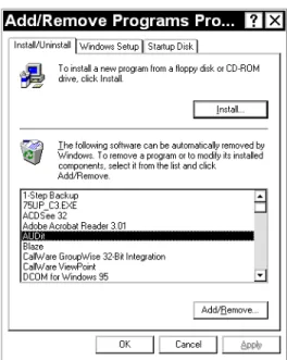
Figure 1-3 Windows™ Add/Remove Programs Dialog Box
Step 1 Click Start, Settings, Control Panel, and Add/ Remove Programs.
Step 2 Highlight AUDit in the program list and click Add/Remove.
Starting the software
Step 1 In the Windows™ Start menu, select Programs, go to the folder which contains AUDit (Larson Davis Programs is the default) and select it. If this is the first time you have used the AUDit™ soft-ware, you will be asked if you wish to create a new database.
Figure 1-4 Create new database Dialog Box
Step 2 Selecting Yes will create a database named
Auditdb.mdb in the current default directory. To create a database later in another directory, select No at this time.
Figure 1-5 Could not open database Dialog Window
Step 3 You will be able to enter a database name and directory in the File, Change Database... menu item. Press OK to acknowledge the prompt and display the main menu.
Software Overview
Main Menu Bar And Navigation The main screen menu bar lists six items. Following stan-dard WindowsTM convention, these pulldown menus may be
accessed with the pointing device or by simultaneously pressing Alt and the underlined letter. The left and right cur-sor keys also allow navigation through the menus, while the up and down cursor keys highlight the various pull down menu options listed below.
NOTE: Wherever stated, a combination of keys can allow direct access to a cer-tain function, for example CTRL+O
brings up the Change Database dialog box.
Menu selections which are invalid under certain circum-stances may be grayed out. For example; until serial com-munication with a System824 sound level meter (SLM) has been established, the Check Battery... selection is unavail-able.
File Menu Figure 1-6 File, Change Database Menu
Change Database... Ctrl+O: Select the measurement data-base which will be used to store instruments, calibrated instruments and other test information
Printer Setup: Setup the printer which will be used for hard copy output of reports and certificates
Exit: End the current test and exit the software
Test Menu
Figure 1-7 Test Menu
Audiometer Test...: Begin an audiometer test sequence Audiometer Test Notes...: Enter notes on audiometer visual inspection and other comments
Booth Test...: Begin a test of the audiometric booth or audio-metric examination area
Instrumentation...: Enter model, serial and correction infor-mation for the test instrumentation used in audiometer cali-bration
Preferences...: Define calibration organization name, address, etc. and set RS232 parameters for communication with the test System824 sound level meter
Stored Measurements: Search database tests by technician name, audiometer model, serial number, and test date
View Menu
Measurement Summary: Display a status screen listing per-formed tests and other information about the current calibra-tion
Toolbar: Show or hide the toolbar
Status Bar: Show or hide the status bar at the bottom of the AUDit™ window
Report Menu
Figure 1-9 Report Menu
Report...: Display the audiometer calibration report Certificate...: Display the audiometer calibration certificate Export...: Export the audiometer or booth test report to a file (depending on which type of measurement is current)
SLM Menu
Figure 1-10 SLM Menu
Connect: Initiate communication with SLM on the serial port defined in Preferences
Disconnect: Terminate communication with the SLM Check Battery...: Verify battery or external power voltage of
Turn Off SLM...: Power down the SLM
Help Menu
Figure 1-11 Help Menu
About AUDit™...: View revision, credits and other software information
Icon Bar
Figure 1-12 Icon Bar
This quick reference tool bar allows direct navigation to a set of most useful screens and functions of the AUDit™ software. Its icons are listed in the order which the functions are normally used in an audiometer test or calibration. In order, these icons are:
• New Measurement • Retrieve Test • Save Current Test • Instrumentation • Booth Test
NOTE: The Icon bar may be moved to a different part of the screen by clicking and dragging on its border, moving it to the desired location
• Audiometer Test • Report
• Certificate • About
Status Bar
Figure 1-13 Status Bar
The status bar displays information on the current pointer function, measurement status, and keyboard such as CAP for capital (uppercase) letters or NUM for numeric keypad. After this overview of the AUDit™ software, you are now ready to configure the system before starting new measure-ments. The next chapter will describe how to setup the soft-ware with test database, printer, instrumentation information and other user preferences.
C H A P T E R
2
Initial Configuration
Before performing a measurement, a few items need to be configured in the AUDit™ software. This chapter covers setting up a test database, configuring the system printer, entering calibration instrumentation information and other user preferences.
Creating or Selecting a Database
The measurement database is a Microsoft Access compati-ble file which contains information about your calibration instruments, as well as audiometer and booth test results. During installation, you may have elected to create a blank database (by default Auditdb.mdb in the current directory). If so, you may skip this section.
Hint: You may also use Ctrl + O to access the Change Database dialog box
To create a new database, click File, Change Database... in the AUDit™ menu to open the Change Database dialog box.
If the name of the database in the text box is valid, clicking Connect will select it. To use another database or create a new database, click Browse.
Figure 2-2 Open Dialog Box
The Open dialog box will appear, allowing you to select the location of the database. To create a database in a new direc-tory, use the Windows Create Directory icon at the top right of the box. In this example, figure 2-3, we have browsed to the following folder: C:\AUDitData\ by selecting My Com-puter, C: and creating the AUDit™ Data folder.
Figure 2-3 Creating a New Directory
The name of the database is entered as New_Clinic, and Open is clicked. After the message in figure 2-4 is con-firmed by clicking Yes, the new database is created.
Figure 2-4 New Database Message
An existing database is selected in the same fashion. If your system was supplied with a database for your calibration equipment (initial.mdb on the last AUDit™ disk), copy this database to the desired location, rename it, and select it. You may skip the Entering Instrumentation section if you already have an instrumentation database.
Configuring the System Printer
Calibration reports and certificates are an essential output of the AUDit™ software. A Windows printer can be selected for hard copy output. Click File, Printer Setup...(figure 2-5)
Figure 2-5 Test, Printer Setup Menu
to display the Print Setup dialog box, figure 2-6, where the active printer is selected. Printer properties, paper size, source and orientation are set here.
Figure 2-6 Print Setup Dialog Box
Refer to your Windows or printer documentation for more information on printer configuration.
Entering Instrumentation
NOTE: When the desired instrumenta-tion is selected for use with an audiome-ter measurement, a copy of the instrumentation selected is made and stored with the measurement. If changes are made to a piece of instrumentation, those changes will not be reflected in the copy that is stored with the measurement.The AUDit™ audiometer calibration software maintains a list of the instruments used in calibration. These are nor-mally certified traceable to NIST - National Institute of Standards and Technology - measurement standards at spec-ified intervals. All this information is entered in the Instru-mentation... Screen, figure 2-8.
Click Test, Instrumentation to display the Instrumenta-tion screen.
Figure 2-8 Instrumentation Screen
Note the types of instruments listed in the upper left rectan-gle: sound level meters, calibrators, microphones, mastoids and preamplifiers. Currently available or defined instru-ments (in this case, sound level meters) are listed in the rect-angle at the lower left. The large area at the right has fields for model, serial number and other information for each type of instrument. If your instrumentation has already been defined for the current database, skip forward to the Setting Preferences section.
click Test, Instrumentation... and select Sound Level Meters in the upper left box of the screen.
Hint: Advance from field to field with the Tab key. Typing the first let-ter of a month will fill in the appro-priate month abbreviation in the pull down box.
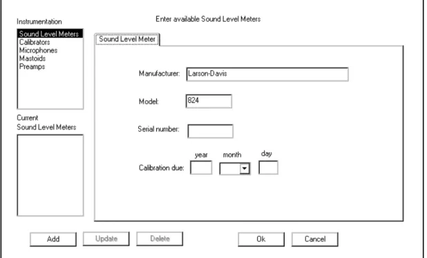
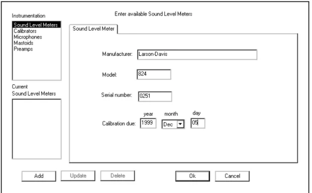
Figure 2-9 SLM information dialog box
Enter the serial number of your 824 and its calibration due date, both available on labels on the back of the instrument. The calibration date must have four digits within 100 years of the computer’s date. Once all fields are completed, click
Add. A new SLM entry will appear in the lower left box. • Click Update to update the instrument information with
new values
• Click Delete to remove the instrument entry from the list
• Click OK to select the instrument
• Click Cancel to terminate data entry without saving the last changes
Entering Calibrator Information
Calibrator information is entered by clicking Test, Instru-mentation... and selecting Calibrators in the upper left box of the screen
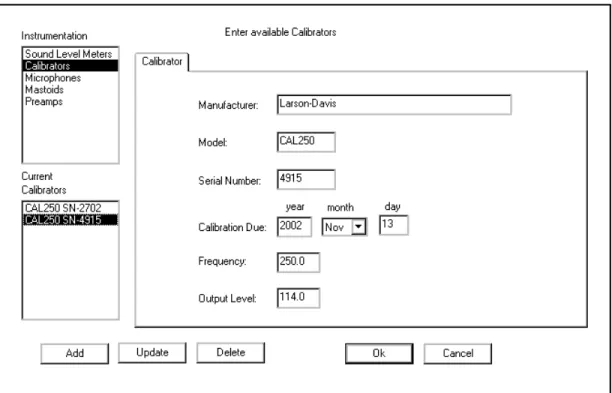
Figure 2-10 .Calibrator Information Dialog Box
NOTE: The Larson Davis CAL250 cal-ibrator provided with your system has a frequency of 250.0 Hertz and a level of 114.0 dB re 20 micropascals. Output fre-quency and level will be used by the soft-ware in the calibration procedure. Entering incorrect values could lead to measurement errors.
Enter the serial number of your calibrator, its calibration due date, frequency and output level. The calibration date must have four digits within 100 years of the computer’s date. Once all fields are completed, click Add. A new SLM entry will appear in the lower left box.
• Click Update to update the instrument information with new values
• Click Cancel to terminate data entry without saving the last changes
Entering Microphone Information
Microphone information is entered by clicking Test, Instrumentation... and selecting Microphones in the upper left box of the screen. Note that this screen has many tabs: Microphone, Low Freq. Response, High Freq. Response, Grid Corrections.
Hint: Microphone frequency response information is available on the calibration chart provided with your microphone. Some audiometric frequencies may not be listed exactly: e.g. 200 Hz is listed as 199.53 Hz. If the frequency labeled in the software is between two fre-quencies on the certificate, you may wish to enter an interpolated value.
Enter the serial number of your microphone, its sensitivity and calibration due date in the Microphone tab. The calibra-tion date must have four digits within 100 years of the com-puter’s date. Do not click add until all tabs are completely filled out. Click on the next three tabs to enter microphone frequency response information, figure 2-12.
Figure 2-12 Microphone Frequency Response Information Dialog Box
NOTE: Microphone frequency
response information will be used by AUDit™ to correct the sound level retrieved from the SLM at each frequency to obtain the actual sound level.
Using data provided by the manufacturer or calibration pro-vider, enter the low, high frequency response and grid cap corrections of your microphone.
High frequency and grid cap corrections may not be neces-sary if you are not performing the calibration of extended frequency audiometers.
• Click Update to update the microphone information with new values
• Click Delete to remove the microphone entry from the list
• Click OK to select the microphone
• Click Cancel to terminate data entry without saving the last changes
Entering Artificial Mastoid Information
The artificial mastoid is used to calibrate the bone vibrator used for bone conduction audiometry. Information is entered by clicking Test, Instrumentation... And selecting Mas-toids in the upper left box of the screen. Note that this screen has two tabs: Mastoid and Response.
Figure 2-13 Mastoids Information Dialog Box
NOTE: The sensitivity of a B&K mas-toid is found on its calibration chart, under the heading Force Sensitivity (including cable) and is in units of mV/N.
Only two types of mastoids are currently supported by AUDit™ software: the Larson Davis Model AMC493 and Bruel & Kjaer 4930 artificial mastoids. Therefore, the Man-ufacturer entry is a pull down menu with those two choices. Enter the manufacturer, model and serial number of your mastoid and its calibration due date. The calibration date
The artificial mastoid response must be entered, figure 2-14, using data provided by the manufacturer or calibration pro-vider.
Response
NOTE: Mastoid frequency response information will be used by AUDit™ to correct the voltage level retrieved from the SLM at each frequency to obtain the actual force level produced by the bone vibrator.
For the Larson-Davis AMC493, enter values listed on the certification document. The Bruel & Kjaer calibration chart typically has three parts. Enter values read from Page 2: Fre-quency Response at constant dynamic force, using the 5.4 N (black) curve.
WARNING! Data must be entered with a leading zero (i.e. 0.02, not .02) and all frequencies should be entered. Do not leave blank fields.
Do not click Add until all tabs are completely filled out.
Hint: Advance from field to field with the Tab key.
• Click Update to update the mastoid information with new values
Hint: Mastoid frequency response information is available on the cali-bration chart provided with your AMC493. Some audiometric quencies may not be listed. If the fre-quency labeled in the software is between two frequencies on the cer-tificate, you may wish to enter an interpolated value.
• Click Delete to remove the mastoid entry from the list • Click OK to select the mastoid
• Click Cancel to terminate data entry without saving the last changes
Entering Preamplifier Information
The Larson Davis System824 precision sound level meter (SLM) is supplied with a Model PRM902 preamplifier. To enter your preamplifier information, click Test, Instru-mentation... And select Preamps in the upper left box of the screen.
Figure 2-16 Preamplifier Information Dialog Box
Enter the serial number etched on the barrel of your pream-plifier and its calibration due date, which is typically the same as that of the 824. The calibration date must have four digits within 100 years of the computer’s date. Once all fields are completed, click Add. A new Preamp entry will appear in the lower left box.
Step 1 Click Update to update the preamplifier informa-tion with new values
Step 2 Click Delete to remove the preamplifier entry from the list
Step 3 Click OK to select the preamplifier
Step 4 Click Cancel to terminate data entry without sav-ing the last changes
Entering Preferences
This configuration item allows the entry of the calibrating organization and selection of communication parameters for the System824 SLM. To enter this information, click Test, Preferences...
Figure 2-17 Test, Set Preferences Menu
to display the Preferences screen. Two system setup items are available in the rectangular area at the upper left of the screen (figure 2-18): Organization and RS232 Port. Click
per-forming the audiometer calibration such as name, address and telephone number.
Figure 2-18 Preferences Dialog Box
This information will appear on the report and calibration certificate. Click OK to enter the information in the data-base.
Click on RS232 Port to access the selection screen for RS232 communications port options. Here you may select port number (COM1 to COM8) and RS232 baud rate (300 to
115kBaud) from pulldown menus. Click OK to confirm your selection.
Figure 2-19 RS-232 Communications Dialog Box
You have now completed the initial configuration of the AUDit™ software. In the next chapter, the system will be assembled and calibrated to perform an audiometric booth ambient level test.
C H A P T E R
3
Audiometer Test Setup
For every audiometer test, the AUDit™ software allows you to fully define the measurement setup as well as the compo-nents of the equipment under test. When a measurement is printed or stored, all this information is recorded in your database. Therefore, an audiometer system only needs to be defined once, saving a lot of time in subsequent tests. In this chapter, you will set up the audiometer test by per-forming this data entry. You will be able to refer to instru-ments which were entered previously in the Instrumentation screen. Audiometers and their many sensor types will also be entered.
Audiometer Test Screen
To begin entering test information, click the Test, Audiome-ter Test... drop down menu item. (Figure 3-1)
NOTE: The status line at the bottom of the window shows:
This will display the Enter Test Location screen (figure 3-2). It is the first of a series of entry screens listed in a column on the left side of the screen. To advance to another screen, use the pointing device to select it from the list:
• Test Location • Equipment • Microphones • Audiometer • Earphones • Bone Vibrator • Speakers
Once data entry is completed, click OK to return to the main AUDit™ screen. Press cancel to end data entry without implementing changes.
Test Location Screen
Figure 3-2 Test Location Dialog Box
This is where customer information is entered.
The Test Location screen (figure 3-2) contains the following fields:
• Customer Name: one line for the customer or company name
• Location: two lines for the location of the audiometer, telephone number or other text data you wish to save.
Select Test Equipment Screen
NOTE: When the desiredinstrumenta-tion is selected for use with an audiome-ter measurement, a copy of the instrumentation selected is made and stored with the measurement. If changes are made to a piece of instrumentation, those changes will not be reflected in the copy that is stored with the measurement.
This screen is one of the multiple tab screens you will find in AUDit™. The equipment used to test the audiometer is selected here from the instrumentation which was entered earlier.
The Test Location screen is composed of four tabs (Figures 3-3 to 3-6).
SLM Tab
Figure 3-3 Sound Level Meter Selection Tab
The SLM selection Tab (figure 3-3) screen contains the fol-lowing fields:
Serial number, Model, Manufacturer, Calibration Due. Only the first field is selectable from a drop down list of the previ-ously entered sound level meters.
Calibrator Tab
Figure 3-4 Calibrator Selection Tab
The Calibrator selection tab (figure 3-4) contains the follow-ing fields:
Serial number, Model, Manufacturer, Frequency, Level, Cal-ibration Due. Only the first field is selectable from a drop down list of previously entered calibrators.
Mastoid Tab
Figure 3-5 Mastoid Selection Tab
The Mastoid selection tab (figure 3-5) contains the follow-ing fields:
Serial number, Model, Manufacturer, Calibration Due, Cou-pler for Larson-Davis Mastoid, Mic used to calibrate the SLM.
The first field is selectable from a drop down list of the pre-viously entered serial numbers, which determines the Model and Manufacturer. The Larson-Davis AMC493 and B&K 4930 artificial mastoids are supported by AUDit™. The two boxes at the bottom of the screen are active only for the appropriate mastoid.
Coupler for Larson-Davis Mastoid
NOTE: Calibration data is currently only available for the AEC100 coupler.
Since the Larson-Davis AMC493 artificial mastoid requires corrections based on the coupler with which it is used this radio button selects either the IEC 318 (Larson-Davis Model AEC101) or the NBS 9A (Larson-Davis Model AEC100) coupler.
Mic used to calibrate the SLM
This box is only enabled with the Bruel & Kjaer artificial mastoid. It is used to specify which microphone will be used to calibrate the SLM before using the mastoid. Mastoid and microphone sensitivities are used to calculate the output level of the bone vibrator.
Preamp Tab
Figure 3-6 Preamplifier Selection Tab
The Preamp selection tab (figure 3-6) contains the following fields:
Serial number, Model, Manufacturer, Calibration Due. Only the first field is selectable from a drop down list of the previ-ously entered preamplifiers.
Select Microphones Screen
Figure 3-7 Select Microphone Dialog Box
The Select Microphones screen (figure 3-7) is a multiple tab screen. It allows you to select the microphone paired with each of the couplers used in the test setup for various audio-metric transducers. There are six different tabs, all of which have the same format. Each microphone tab contains the fol-lowing fields:
Serial number, Model, Manufacturer, Calibration Due. Only the first field is selectable from a drop down list of previ-ously entered microphones. If a specific coupler will not be used in the audiometer calibration, you do not need to enter it. The various tabs are:
IEC 318 Mic Tab
Select the microphone used with the IEC 60318 coupler. This coupler is designed in accordance with International
Electrotechnical Commission (IEC) standard IEC 60318-1 (1998-07): Electroacoustics - Simulators of human head and ear - Part 1: Ear simulator for the calibration of supra-aural earphones. It presents a known acoustical impedance to the test earphone. When used with adapters defined in the same family of standards, the IEC 318 coupler can also calibrate supra-aural earphones in an extended frequency range. The Larson Davis AEC101 artificial ear is designed to meet these standards.
NBS 9A Mic Tab
Select the microphone used with the NBS 9A coupler. This coupler was originally developed by the National Bureau of Standards, now called the National Institute of Standards and Technology (NIST). It is specified in American National Standard Institute Specifications for Audiometers, S3.6-1996 for calibrating earphones used in audiometry. The Larson Davis AEC100 artificial ear is designed to meet this stan-dard.
IEC 711 Mic Tab
Select the microphone used with the IEC 60711 coupler. This coupler is described in IEC 60711 (1981-01) Occluded-ear simulator for the measurement of Occluded-earphones coupled to the ear by ear inserts. The standard specifies an occluded-ear simulator for the calibration of insert occluded-earphones from 100 Hz to 10 kHz.
HA-1 Mic Tab
Select the microphone used with the HA-1 coupler. This coupler is described in IEC 60126 (1973-01) IEC reference coupler for the measurement of hearing aids using ear-phones coupled to the ear by means of ear inserts. The
cou-pler is designed to load the earphone with a specified acoustic impedance when determining the performance of air-conduction hearing aids using earphones coupled to the ear from 200 Hz to 5kHz.
HA-2 Mic Tab
Select the microphone used with the HA-2 coupler. This coupler is also described in IEC 60126 (1973-01) IEC refer-ence coupler for the measurement of hearing aids using ear-phones coupled to the ear by means of ear inserts. The coupler is useful in determining the performance of insert earphones with a nub or molded ear insert. It may also be used to qualify earphones which use a tube to connect to an ear mold or insert.
Open Air Mic Tab
Select the microphone used for open air measurements such as the ambient noise level measurement of the Booth Test, or speakers tests.
Audiometer Description Screen
Figure 3-8 Audiometer Description Screen
The Audiometer Description screen is a multiple tab screen. It contains information on the audiometer (or signal genera-tor) under test, while its transducers are defined in the remaining screens of the setup items. The Audiometer Description screen is composed of three different tabs to describe the audiometer and its tested output frequencies.
Audiometers Tab
The Audiometers Tab contains the following fields:
• Model, Manufacturer, Serial number, Audiometer Type, Inventory Number, Date last calibrated, Calibration due date, Number of Channels, Channel to test, FM tone modulated at ___% of carrier frequency at a rate of ___ Hz. Some details on the entries follow.
NOTE: American National Standard S3.6-1996 Specifications for Audiome-ters specifies the designation of audiom-eters satisfying the standard. The minimum required facilities for each des-ignation are listed in table 1 of the stan-dard.
• Audiometer Type: Enter this descriptive pure tone audiometer type number, which should be stated in the audiometer specifications or labeled on the instrument itself. Additional suffixes for high frequency, speech or free field equivalent are not available but may be entered in the Audiometer Test Notes... comments.
• Number of Channels: Enter the number of channels if the tested audiometer has multiple channels. Drop down menu selections are 1 and 2.
NOTE: ANSI S3.6-1996 pure tone Type 1 and 2 audiometers must have a facility for presenting a frequency modu-lated tone.
• Channel to test: Enter the channel which will be tested. Depending on the number of channels, you may select 1 or 2 in the drop down menu.
• FM tone modulated...: Enter the audiometer's frequency modulation percentage and rate of modulation. These values will be verified in the appropriate test.
Low Frequencies Tab
The Low Frequencies tab allows you to specify which ometer frequencies will be tested. It contains a list of audi-ometer frequencies from 125 to 8000 Hz. Each frequency may be selected by clicking on the box to its left. Click again to deselect a frequency. The Set to Default Frequencies but-ton selects only the common frequencies: 125, 250, 500, 750, 1000, 1500, 2000, 3000, 4000, 6000, and 8000 Hz. Additional frequencies may be added after setting the default frequencies.
High Frequencies Tab
The High Frequencies tab allows you to specify which high frequencies available on the audiometer will be tested. These frequencies are used by extended high frequency pure tone audiometers (ANSI S3.6-1996 Type xHF designation). Each frequency may be selected by clicking on the box to its left. Click again to deselect a frequency.
Select Earphones Screen
The Select Earphones screen (figure 3-9) is composed of three different tabs, one each for supra-aural, insert, and cir-cumaural earphones. Each tab lets you enter the audiometer earphones and the respective artificial ear couplers used in the test setup. If a certain type of earphone is not used, it does not need to be defined.
Figure 3-9 Select Earphones screen, showing supra-aural tab.
Supra-aural Tab The Supra-aural Tab contains the following fields:
Model, Manufacturer, Right Serial number, Left Serial num-ber, Coupler.
The Model entry is a drop down menu with the following choices: TDH 39, TDH 49 and TDH 50. The Manufacturer field is set as Telephonics. The Coupler field has two radio buttons with a value of IEC 318 or NBS 9A. NBS 9A is the default setting.
Insert Tab
Figure 3-10 Insert Earphone Tab
The Insert tab (Figure 3-10) contains the following fields: Model, Manufacturer, Right Serial number, Left Serial num-ber, Coupler.
The Model entry is a drop down menu with the following choices: ER-3A and 3A. The Manufacturer field defaults to Etymotic for the ER-3A and EARtone for the 3A model. The Coupler field has three radio buttons with a value of IEC 711, HA-1 or HA-2.
Circumaural Tab
Figure 3-11 Circumaural Earphone Tab
NOTE: AUDit™ uses the supra-aural earphone reference equivalent threshold sound pressure levels (RETSPLs) in dB re 20 micropascals for common ear-phones listed in Table 6 of ANSI S3.6-1996. The RESPLs referred to the appro-priate coupler are used in the calibration process. In the case of insert earphones, The RETSPLs listed in Table 7 of ANSI S3.6-1996 are used. Circumaural ear-phones interim RETSPLs listed in Table C1 are used by AUDit™. Contact Lar-son-Davis for information on enabling additional earphones with the manufac-turer's valid RETSPL data.
The Circumaural tab (Figure 3-11) contains the following fields:
Model, Manufacturer, Right Serial number, Left Serial num-ber, Coupler.
The Model entry is a drop down menu with the following choices: HDA200 and HV/1A. The Manufacturer field defaults to Sennheiser for the HDA200 and Koss for the Model HV/1A. The Coupler field defaults to IEC 318 only.
Bone Vibrator
Figure 3-12 Bone Vibrator Description Screen
The Bone Vibrator Description screen (Figure 3-12) con-tains the following entry fields: Manufacturer, Model, and Serial Number. Enter the appropriate information for the vibrator in use with the calibrated audiometer.
Speakers
Figure 3-13 Speaker Description Screen
The Speaker Description screen (Figure 3-12) contains two tabs, Left and Right, each with the following entry fields: Manufacturer, Model, and Serial Number. Enter the appro-priate information for the speakers in use with the calibrated audiometer.
C H A P T E R
4
Booth Test or Ambient Noise
Level Test
You have now configured the AUDit™ software in prepara-tion for your first test. In this chapter, the system will be cal-ibrated to perform a measurement of ambient levels in the audiometric test room. This is referred to as a booth test in the AUDit™ software. In doing this test, we will also cover connecting to the SLM and calibrating it.
If ambient noise levels in an audiometric test room are excessively high, they can have a masking effect on the sub-ject, effectively raising the measured hearing threshold. This is most likely to occur if very low hearing threshold levels are being measured.
NOTE: This and the other ANSI stan-dards mentioned in this manual are available from the Acoustical Society of America, 120 Wall St., 32nd Floor, New York, NY, 10005-3993, (212)248-0373.
AUDit™ allows simultaneous assessment of noise levels for audiometric measurements with ears covered or not covered, in the frequency ranges of 125, 250 and 500 Hz to 8000 Hz. This test and its pass/fail limits are based on the recommen-dations of American National Standard on Maximum Per-missible Ambient Noise Levels for Audiometric Test Rooms, ANSI S3.1 - 1991 (ASA 99-1991).
In order to consider the worst case conditions for an audio-metric test, the ambient noise test should be performed with all possible noise sources present. If certain sources are operating at certain times but not at others, it may be neces-sary to schedule the measurement accordingly.
Assembling the system
The Larson Davis System824 precision sound level meter meets all the requirements of the aforementioned standard for the measurement of ambient noise level in the audiomet-ric test room. Its low self-noise and internal fractional octave band measurement capability enable it to accurately measure octave and third octave levels much below the minimum required levels, when using a high sensitivity microphone such as the Larson Davis model 2575 or 2570.
Equipment for Booth Test
The equipment listed below is suggested for ambient noise testing with AUDit™.
• PC with AUDit™ • CBL006 serial cable
• System824 precision sound level meter
NOTE: The microphone/preamp assem-bly may be suspended or supported with a suitable microphone clamp. If the dimensions or construction of the audio-metric test room require a longer length of cable or the use of patch panels, care must be taken not to introduce ground loops or other problems which can lead to higher system self-noise levels.
• EXC010 extension cable (optional) • PRM902 preamplifier
• 2575 microphone
• ADP008 1/2 inch preamp to 1 inch microphone thread adaptor
Assembling the system
Step 1 Connect the CBL006 from the SERIAL connector on the butt plate of the 824 SLM to the active serial port on the computer
Figure 4-1 Connecting CBL006 to 824
Step 2 Install the PRM902 microphone preamplifier directly on the SLM or use the EXC010 extension cable by matching red dots on opposite gender connectors
Figure 4-2 Connecting EXA010 extension cable to 824 and PRM902
Step 4 Thread the 2575 or other microphone onto the PRM902 preamplifier, being careful not to strip the threads
Figure 4-3 Connecting PRM902, ADP008 and 2575 Microphone
Connecting to the SLM
If AUDit™ is not active, run the software by clicking Start,
Programs, Larson Davis Programs, AUDit™ (if AUDit™ was installed in the default folder). Verify commu-nications port options in the Test, Preferences..., RS232 Port tab. The System824 should have the same settings.
NOTE: The Communications settings on the System824 are accessed by pressing
T, scrolling to Communications, and pressing the c key. Please refer to the 824 reference manual (I824.01) for complete instructions.
Click SLM, Connect
Figure 4-4 Connect Menu
to establish connection with the SLM. You may verify bat-tery level by clicking SLM, Check Battery... (Figure 4-4)
Figure 4-5 Battery Check Window
In this case the battery voltage is 12.1 Volts (figure 4-5), with external power. Internal battery status is reported in percent. Measurements should not be attempted with inter-nal battery readings lower than 10%.
System SPL Calibration
NOTE: Calibrator and microphone must be selectecd as shown in the next section before calibration check or change
The reference level of the sound level meter is calibrated with the use of the CAL250 or another precision calibrator. This instrument generates a known sound pressure level (SPL) relative to 20 micropascals. To calibrate, click SLM, Calibration...
Hint: Do not hold or bump the cali-brator during calibration. Vibrations may affect readings. All measure-ment system components should have reached a stable temperature before calibrating. Your calibrator should remain on for the duration of the calibration (about 30 seconds). If its battery is low, replace it to extend the tone duration.
AUDit™ will display the SLM Calibration dialog box. Select your calibrator and microphone in the pull down menus. Note that the current level and the difference between it and the calibrator output level are displayed at the top of the box.(Figure 4-6) You may use this display to check calibration without changing it, then click on Close to exit. To change calibration click Set Calibration.
A prompt will ask you to turn on your calibrator. The System824 must be calibrated in two ranges, with a stabili-zation period between both calibrations. Please follow the prompts.
Performing the Booth Test
Once the SLM has been calibrated, the ambient noise levels can be measured. Select the Test, Booth Test menu item to display the Booth Ambient Levels Measurement screen.
Figure 4-7 Measurement Location screen
A number of tabs are displayed (figure 4-7), as follows: Location Contains text fields for Booth, Customer Name, and
Location of the room getting measured. Enter the appropriate values.
Figure 4-8 SLM selection and Information Window. (Preamplifier and Microphone windows are similar.)
Calibrator Tab
Figure 4-9 Calibrator selection and Information Window
The Calibrator tab (figure 4-9) contains the same fields as "SL Meter" as well as the frequency and the output SPL of the calibrator selected from the pull down menu.
NOTE: A message (Figure 4-10) will be displayed while the measurement is per-formed.
After selecting the equipment used for the ambient test, click
Figure 4-10 Ambient Level Test Message Window
125 - 8K Hz, 250 - 8K Hz, and 500 - 8K Hz Tabs
NOTE: The limits used in these tabs are from Tables III and B2 of the American National Standard on Maximum Permis-sible Ambient Noise Levels for Audio-metric Test Rooms ANSI S3.1 - 1991 (ASA 99-1991). The limits for the third octave bands centered at 31.5 and 63 Hz are interim values derived from the assumption that masking from lower fre-quency noise affects audiometric mea-surements at 125 Hz and above.
Once the measurement is completed, these three tabs show Booth Test results.(Figure 4-11) Failed frequencies are indi-cated with a red mark. In this case, the failed 63 Hz third octave measured SPL was 46.3 dB SPL, whereas the stan-dard allows at most 43.0 and 37.0 dB for covered and not covered ears. The exceeded limit values are displayed between parentheses. Since the limits of the 125 - 8K Hz test are the most stringent, if no failure exists on this tab, the oth-ers tabs will also show no failure.
Saving the Booth Test
Once the test is complete, you may save it by clicking OK at the bottom of the Booth Ambient Levels Measurement screen, which will display the dialog box shown in figure 4-12:
Figure 4-12 Ambient Level Test Save Window
where you can enter a descriptive string which will be used to index this record in the measurement database. To search previous booth tests, refer to the chapter on Stored Measure-ments.
Suspecting Instrument Noise?
Should the readings of the ambient test be questionable, you may want to check the measurement system noise. There are a few ways to do this. One simple alternative is to repeat the measurement with the non-functioning calibrator left on top of the microphone. Another would be to do the booth test without a bias voltage on the microphone. This has the effect of reducing its sensitivity and will show the electrical noise of the system. The results of this second method are shown in figure 4-13.
Figure 4-13 Booth Ambient Levels Window
As you can see, the noise level at the third octave centered at 63 Hz is -7.3 dB SPL, well below the failing ambient level. This would indicate that the noise was not produced in the instrumentation.
Hint: To remove the bias voltage from the microphone, stop the 824 and press S(Setup), r(Right Arrow) to modify the Audtest.AUD settings. Scroll to SLM, press r
(Right Arrow) and scroll down to modify SLM parameter Transducer. Press the c(Check key) and per-form an Overall Reset to select Elctrt. DO NOT FORGET TO RESET THE TRANSDUCER TO Condnsr BEFORE MAKING NEW MEASUREMENTS.
This measurement has demonstrated the ease of use of the Larson Davis audiometer calibration system. In the remain-der of this manual, a full audiometer calibration will be per-formed.
C H A P T E R
5
Assembly of the Audiometer Test
System
NOTE: You must use the setup defined for each transducer earlier in the AUDit™ software as described in the Audiometer Test Setup chapter. This will ensure the proper microphone correc-tions, RETSPL’s etc. are applied to the measurement.
This chapter covers test configurations for the audiometer transducers which can be calibrated by the LD audiometer calibration systems. The recommended configurations for various earphones will be described first. Common elements such as the PC to System 824 SLM and PRM902 preampli-fier connections, inspection and calibration procedures are explained next. Please contact Larson Davis if you have any system assembly questions not covered in this manual.
Audiometer Transducer Test Configurations
The table below lists some typical audiometer transducers, many of which are covered in specifications such as Ameri-can National Standards Institute Specifications for Audiom-eters, S3.6-1996. When configuring the audiometer transducer test, the AUDit™ software suggests or defaults to appropriate setups. These test setups are covered in greater detail in subsequent sections.
Transducer Type Example Suggested Setup Comments
Supra-aural earphone Telephonics TDH-39, 49, 50
AEC100 NBS 9-A cou-pler or AEC101 IEC 318 artificial ear
Use 4-5 N weight. Test up to 8000 Hz. Circumaural earphone Sennheiser HDA200 AEC101 IEC 318
artifi-cial ear with MAEC101.06 Type 1 adaptor plate
Use 9-10N weight. Extended frequency tests up to 16000 Hz may be performed.
Circumaural earphone Koss HV/1A AEC101 IEC 318 artifi-cial ear with
MAEC101.07 Type 2 adaptor plate
Use 9-10N weight. Extended frequency tests up to 16000 Hz may be performed.
Bone vibrator Radiophone B-71 AEC100 NBS 9-A cou-pler and AMC493 artifi-cial mastoid
Use 9-10N weight
Speakers Speakers Use ambient noise level
test setup from Chapter 4.
Insert earphone Insert Earphone 2.0 cm3 or Type 2
cou-pler
Refer to earphone and coupler manufacturer information.
Connecting the PC, 824 and PRM902 Preamplifier
WARNING! Before continuing, ensure that the 824 SLM is turned off. Sensitive circuitry may be adversely affected by transients dur-ing assembly if the 824 is on. The 824 should remain off until the sys-tem is fully assembled.
Step 1 Connect the CBL006 RS-232 cable from the SERIAL connector on the butt plate of the 824 to the active RS-232 port on the computer (figure 5-1).
Figure 5-1 Connecting CBL006 to 824
Step 2 Connect the male end of the EXA010 extension cable to the nose cone of the 824 by matching the red dots on mating connectors (figure 5-2).
Step 3 After the PRM902 microphone preamplifier has been inserted in the appropriate coupler, (see below) connect it to the nose cone of the 824 with the EXA010 extension cable by matching the red dots on mating connectors (figure 5-3).
Figure 5-3 Preamp connecting to extension cable and to AEC100.
Step 4 The 824 SLM may now be turned on to select RS-232 parameters. Press the v key on the 824.
Step 5 Press T, scroll down with the d to Communi-cation and press r to edit Serial Comm. parameters. Set the parameters as desired. 9600 Baud, serial address 000 and Hdwr flow control are suggested.