DESIGNING BIOMIMETICALLY INSPIRED MATERIALS FOR POTENTIAL ORTHOPEDIC TISSUE ENGINEERING APPLICATIONS
Jason Christopher Dyke
A dissertation submitted to the faculty at the University of North Carolina at Chapel Hill in partial fulfillment of the degree of Doctor of Philosophy in the Department of Chemistry
Chapel Hill 2014
ii ©2014
iii ABSTRACT
Jason Christopher Dyke: Designing Biomimetically Inspired Materials for Potential Orthopedic Tissue Engineering Applications
(Under the direction of Wei You)
Described herein is the progress made towards modifying and improving established
Hydroxyapatite-Gelatin (HAp-Gel) bioceramics. Initial attempts to improve this composite were aimed at incorporating a biomimetic polymer into the HAp-Gel matrix in order to improve long-range interactions in the system. This was done in order to address shortcomings of HAp-Gelatin composites (e.g. low toughness) without sacrificing its favorable properties. Novel degradable copolymers were used, inspired by lactide and trimethylene carbonate monomers. These copolymers demonstrated tunable properties (e.g. molecular weight, glass transition temperature) and were shown to improve fiber bridging in a composite, without sacrificing biocompatibility. Unfortunately, these composites were plagued by poor interfacial adhesion.
To address this, a catecholamine based polymer, polydopamine (PD), was incorporated into this HAp-Gel ceramic matrix. This macromolecule has demonstrated excellent adhesion to numerous substrates. This PD containing composite was shown to have a strong dependence of mechanical properties on processing temperature. Specifically, it was shown that at low temperatures, PD is able to polymerize unimpeded, while the sol-gel component is hindered. The sequential PD/sol-gel
polymerizations leads to a unique interpenetrated polymer network with excellent mechanical properties and good biocompatibility.
iv
v
ACKNOWLEDGEMENTS
First and foremost I would like to thank my advisor Wei You for his knowledge and patience with me throughout the last five years. Synthetic organic chemistry has not always been the easiest job for me, but throughout my time at UNC Wei’s patience has helped me become a better chemist and scientist. More importantly, Wei has been an incredible mentor and friend to me during my time at UNC Chapel Hill, and he is a major reason I will remember my time in North Carolina so fondly. I would also like to thank Dr. Ching-Chang Ko for his guidance and help while we established a new collaboration between the You and Ko labs. Dr. Ko’s advice and input were invaluable for getting our collaboration off the ground and his support helped me branch into the exciting field of biomaterials science.
vi
I would like to acknowledge Professors James Cahoon, Valerie Ashby, and Scott Warren for serving as members on my defense committee and thank them for taking the time to help me in my transition away from my graduate studies. My gratitude is also with John Whitley, Wonhee Jeong, and Dominica Wong for their invaluable help with experimental design.
I would also like to thank my undergraduate advisor, Dr. Lyudmila Bronstein. Her guidance through my undergraduate work was vital to me, and helped me take an interest in research and materials science in particular. Her kindness and knowledge helped lead me to a path towards UNC, for which I am eternally grateful to her.
vii
To my family,
viii
TABLE OF CONTENTS
LIST OF TABLES……….…ix
LIST OF FIGURES………...………...…x
CHAPTER 1: INTRODUCTION TO CURRENT BONE-REPAIR STRATEGIES……….………...1
1.1 Limitations of Natural Bone Treatment Options .….……....………...3
1.2 Permanent Synthetic Bone Replacement Materials……….………...4
1.3 Temporary Bone Replacement Options and Scaffolds……….…….……….8
1.4 Hydroxyapatite-Gelatin Composite Materials.……….13
REFERENCES………..………..………20
CHAPTER 2: PERFORMANCE OF BIOCERAMIC COMPOSITES CONTAINING POLY(L-LACTIDE-CO-PROPARGYL CARBONATE)-G-AZIDO SILANE………..…...…23
2.1 Introduction to Polymer Bioceramic composites ……….………...………….23
2.2 Monomer and Cross-Linker Synthesis ……….…29
2.3 Synthesis and Characterization of Copolymers from Sn(Oct)2 Catalyzed ROP ….…….…..30
2.4 Post-Polymerization CuAAC Click Functionalization and Amalgamation ………...36
2.5 Conclusions ……….…….42
2.6 Experimental Details ……….…….….…….…………..….………...……….……….…43
REFERENCES……….……….……….……….……….……….……….52
CHAPTER 3: THE ROLE OF TEMPERATURE IN FORMING SOL-GEL BIOCOMPOSITES CONTAINING POLYDOPAMINE….………..…..………...……....…………55
3.1 Motivations and Background on HAp-Gel and Polydopamine Containing Materials……….56
3.2 Forming HAp-Gemosilamine Composites: Observation and Hypothesis ..……….…58
3.3 Experimental Design: Practical Consideration..….… ………..61
3.4 Temperature Dependence of The Sol-Gel Reaction of enTMOS ……….………...63
ix
3.6 Biocompatibility: MTS Assay ……….……….……….67
3.7 Conclusions……….……….……….68
3.8 Experimental Details………..………...………….…….………...….……….…70
REFERENCES……….………...….……….……….……….……….75
CHAPTER 4: THE ROLE OF TEMPERATURE IN FORMING SOL-GEL BIOCOMPOSITES CONTAINING POLYDOPAMINE….………...………76
4.1 Introduction to Catecholamine inspired adhesives………..….76
4.2 Using untethered catechol-amine pairs to mimic polydopamine..…..……….…84
4.3 Film Deposition Studies ….…….…….…….…….………...…...…...…...…...…....….…..86
4.4 Film Adhesion Studies ………..………...89
4.5 Experimental………..……….92
4.6 Conclusions……….……….93
REFERENCES……….………...….……….……….……….……….95
CHAPTER 5: CONCLUSIONS AND FUTURE DIRECTIONS………..….………...………….……97
5.1 Plans for Improving Biomimetic Composites...………..….98
5.2 Further Studies on Catecholamine Adhesives………...…..……….…98
5.3 Improving Adhesive Properties………...………..….100
5.4 Concluding Remarks………...………...…..……….…101
x
LIST OF TABLES
xi
LIST OF FIGURES
Figure 1.1: Hierarchical structure of bone……...………...……...2
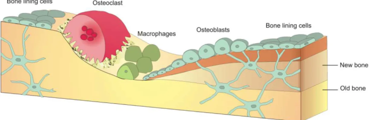
Figure 1.2: Bone remodeling behavior……...………...……...7
Figure 1.3:Biomaterial interactions with human tissue……...………...…….10
Figure 1.4: Illustration of mechanical strength transfer from scaffold to newly formed tissue…..……...12
Figure 1.5: Hydrolysis condensation of silanes leading to sol-gel materials.……….………...……..14
Figure 1.6: HAp-Gemosil scaffold properties...……...………...……...15
Figure 1.7: Prelminary biocompatibility and osteoconductivity of HAp-Gemosil………..17
Figure 2.1: Synthesis of PC monomers..……...………...……....29
Figure 2.2: Synthesis of AS graft monomer ...………...……...30
Figure 2.3: ROP copolymerization of LLA and PC...………...……...31
Figure 2.4: MW and % PC incorporations for P(LLA-co-PC) copolymers………...…….32
Figure 2.5: NMR analysis of P(LLA-co-PC) copolymers ……...………..…...…….33
Figure 2.6: DSC Traces of P(LLA-co-PC) copolymers.………...…...……...35
Figure 2.7: Post-polymerization functionalization for P(LLA-co-PC) copolymers………..……..37
Figure 2.8: Amalgamation of P(LLA-co-PC) copolymers with HAp-Gemosil…….…….……....……...38
Figure 2.9: MTS Assay of P(LLA-co-PC) .……….………..……..39
Figure 2.10: Changes in biaxial flexure strength……….40
Figure 2.11: Changes in compressive strength………41
Figure 2.12:Biaxial flexure testing apparatus………...……...49
Figure 3.1: Compressive testing of gemosilamine ...………...……...59
Figure 3.2: Illustration of sequential enTMOS and PD polymerizations. ………...……...61
Figure 3.3: Mass loss data for temperature dependence of enTMOS polymerizations..…………...…….64
Figure 3.4: UV-vis data showing temperature dependence of PD polymerizations ……...…....…...…….66
Figure 3.5: MTS assay for gemosilamine composites………...…...……...68
Figure 3.6: CT imaged Gemosilamine scaffold………...………..……..69
xii
Figure 4.2: Conversion of tyrosine to L-Dopa……….78
Figure 4.3: Structures of major amino acids present in mefps….. ………...……...79
Figure 4.4: Proposed dopamine polymerization mechanism………...………...….81
Figure 4.5: Biosynthetic pathway forming eumelanin…... ……...………..…...…….81
Figure 4.6: Alternative proposed PD mechanism.………...…...………..…...82
Figure 4.7: Structure of dopamine compared to catechol and propylamine………..……….84
Figure 4.8: UV-vis of catecholamine solution polymerizations…...………...85
Figure 4.9: XPS data for catecholamine coated AU substrates.……….……….………..……..87
Figure 4.10: UV-Vis of catecholamine deposition on glass surfaces ……….88
Figure 4.11: Demonstration of catecholamine film growth on glass……...………89
Figure 4.12:Adhesive testing of catecholamines...………...……...90
Figure 5.1:Structure of other bound catecholamines and their polymers.………...……...99
1
CHAPTER 1: INTRODUCTION TO CURRENT BONE-REPAIR MATERIALS AND DESIGN STRATEGIES
Bone injuries are caused by numerous factors such as disease, aging, or trauma. When left untreated, this damage can lead to chronic pain and loss of function, both of which will greatly lower a person’s quality of life and even expedite death It has been reported that every year, over 1.5 million American’s suffer a fracture caused by bone disease, and in 1995 the total expenditure for osteoporosis related treatments exceeded $13 billion in the United States.1 Despite the prevalence of these injuries and the need to adequately replace the function of this damaged tissue, current treatment options remain limited due to the complexity of natural osseous tissue.
2
and organic components are highly organized on several levels to form a complex hierarchical structure, illustrated in Figure 1.1.3 These HAp-coated collagen fibers are wound together to create larger mineralized collagen fibrils, which can be formed into lamellar sheets, which ultimately wrap together to form the final bone tissue. The intricate, highly organized structuring of human bone helps it to achieve the remarkable mechanical properties (i.e. low weight with high compressive strength) that are crucial for skeletal function.
Figure 1.1 Hierarchical structure of bone, starting with collagen nucleating HAp, and being formed into several layers to maximize mechanical strength while minimizing weight.
3
considerable advances which have been made to address these concerns, all current treatment strategies and materials have significant drawbacks. For this reason, replicating the properties of bone with natural or synthetic biomaterials remains an elusive goal.
1.1 Limitations of Natural Bone Treatment Options
Because of its unique structural organization and properties, natural bone presents the best match for replacing lost or damaged tissue. Although using bone is the ideal replacement, current methods utilizing natural tissue can have serious drawbacks.
Replacing bone from natural sources,, called grafting, involves taking healthy tissue from a donor for implantation into the afflicted individual. Currently, several methods of graft treatments are available; allografting involves harvesting tissue from a genetically different donor of the same species, while xenografts involve taking donor tissue from animal sources. Both of these methods present unique challenges. For example, these foreign tissue grafts can be rejected at the implant site, due to the same immunologic factors observed with other transplants. This rejection by the host’s immune system can cause additional damage at the implant site.4 Furthermore, these grafts present a greater risk for infection than other replacement strategies, further complicating the potential therapeutic benefit.5 For these reasons, it is generally believed that autografts are a superior source of natural bone tissue.
4
limited tissue supply, simply due to the lack of suitable donor sites on a patient. Autografts also present the risk of donor site morbidity, a complication which arises when tissue surrounding the newly excised begins to necrose, creating another bone injury while attempting to treat the first.6 Though complications are not incredibly common using autografts, patients who require a substantial amount of tissue to be excised, or patients who are already immunocompromised experience greater risks of complications.7 In addition to this, many patients report chronic pain from the implant site, lowering the thereapeutic value of this approach.8 These possible complications ultimately make the autograft option impossible for some patients, and sub-optimal for many more. The potential limitations and negative consequences grafting treatment options highlight the need for improvements through alternative synthetic treatments.
1.2 Permanent Synthetic Bone Replacement Materials
5 as in blends with other, stronger materials. 13-15
Most early attempts in designing bone replacement alternatives were focused around finding materials which would permanently assume the function of the injured tissue.16 The majority of these early implants were designed to be nonporous and inert. Through this strategy, it was hoped that the implanted material would not negatively interfere with the function of the body, nor would they be altered by implantation. By using inert materials, it was also believed that these materials would resist degradation through wear and corrosion, helping extend the lifetime of these materials to make permanent implantations feasible. Nonporous materials also seemed favorable as they provided a complete barrier at the interface of the implant and the hard tissue, minimizing potential adverse interaction with the surrounding tissue. Several types of permanent, bioinert material implants were attempted, including silica and aluminum-oxide ceramics, as well as metals such as steel and titanium alloys. After implantation, these implants were usually observed to be sequestered by a fibrous tissue of variable thickness, allowing them to serve their purpose while not interfering with the body. 17
6
additional injury and necessitating further surgery in order to repair the damage caused by the implant. Since these materials are designed to be permanent implants, it is often difficult to repair or replace them, leading to further complications and hindering the therapeutic value of this approach.
Modulus mismatch between implant and bone can lead to other undesired effects on the function of the implant through a process known as stress shielding. This occurs when a high modulus implant shields the surrounding bones from feeling mechanical loading associated with normal skeletal function.24 The lack of mechanical load reaching the surrounding tissue causes the native tissue to lose strength, as the body deems it a waste of resources to continue to maintain the osseus tissue surrounding the implant. This process leads to drastically weakened tissue, which is then more susceptible to future injury. Therefore, when stress on a tissue is being shielded by an implant, the risk of the surrounding tissue failing is just as important as the risk of the implant itself failing.
7
Figure 1.2 Resorption of osseous tissue by osteoblasts and macrophages, and the subsequent deposition of new tissue by ossification through osteoblast activity.
Reinforcing these bones lowers the risk of future injury associated with heavy use, and this repair strategy allows the body to focus on the bones most affected (i.e. the most damaged) and reinforce them accordingly. Conversely, if the tissue stops feeling the effect of skeletal loading (i.e. it is being stress shielded) the remodeling behavior will result in the body resorbing the tissue.26 This happens because it is metabolically costly to maintain bone, and if the body recognizes there is no need to reinforce and maintain a portion of osseous tissue, it will degrade this tissue in order utilize the nutrients in a more useful way elsewhere.
8
matrix (ECM.)28 This newly laid ECM effectively attaches the new osseous tissue to the permanent implant, creating a strong mechanical bond between the two. At the same time, provided the pores are suitably designed, a channel is created between the newly formed ECM and the surrounding healthy tissue. This allows for nutrients to move into the new cells, and waste to be removed, effectively expanding healthy tissue into, and around, the permanent implant. This approach was observed to eliminate many negative consequences of other nonporous permanent implants, such as implant loosening and encapsulation.29 Despite the improvements these biologically fixed implants demonstrated over nonporous implants, major concerns such as modulus mismatch, and longevity remained important concerns, necessitating investigation of better materials.
1.3 Temporary Bone Replacement Options and Scaffolds
There are other classes of ceramics, however, which are considered bioactive, allowing favorable interactions with biological tissue to take place at the implant surface. These materials are capable of achieving “bioactive fixation” whereby a material such as a bioglass can form a favorable interface with the tissue surrounding the implant.30 Bioactive fixation involves creating mechanical bonds like those seen with biological fixation, but in addition, strong chemical bonding is achieved through the implant material’s inherent ability to react with the body. Since these materials are somewhat similar to bone, and not inert towards the body, the newly forming ECM can effectively incorporate a small amount of these ceramic materials directly into itself.31 This gives better adhesion than the biologically “fixed” implants mentioned above, simply by virtue of chemically bonding the implant material, to a limited degree, into the ECM of the cells which interpenetrate the scaffold after material implantation.
9
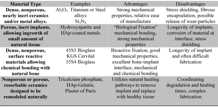
excellent potential for therapeutic applications: resorbable bioceramics.31,32 These materials are similar to the bioactive ceramics mentioned above, but they differ in several important ways. Primarily, these materials are not permanent, and are capable of degrading over a specified period of time. This allows the slow interpenetration of osseous tissue, which leads the “bioactive fixation” to happen continuously at the materials surface. Small portions of the material are incorporated into the newly forming ECM before degrading away, and as the material degrades it is slowly replaced by natural tissue. Table 1.1 gives examples of each of the classes of biomaterials discussed above, and gives a summary of their interactions with the body.
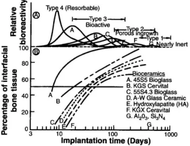
Figure 1.3 summarizes different classes of biomaterials, and gives examples of each type, also briefly discussing how the body interacts with each of these different classes. As can be seen in Figure 1.3, implants with low relative bioactivity (e.g. Al2O3 or Si3N4) exhibit effectively no interfacial bone after long implantation times, indicating they are largely
Table 1.1: Classes of Biomaterials and General Properties
Material Type Examples Advantages Disadvantages
Dense, nonporous, nearly inert ceramics
and/or metal alloys.
Al2O3, Titanium or Steel alloys
Si3N4
Strong mechanical properties, relative ease
of manufacture
Stress shielding, fibrous encapsulation, possible release of wear-particles Porous, inert implants,
allowing ingrowth of small amount of
natural tissue Hydroxyapatite and HAp-coated metals “Biological Fixation” mechanical bonding, strong mechanical properties
Longevity of implants, corrosion of material at
interface, stress shielding Dense, nonporous,
surface reactive materials allowing chemical bonding with
natural bone
45S5 Bioglass KGS Cervital 55S4 Bioglass
Bioactive fixation, good mechanical properties, excellent bone-implant interface, mechanical and chemical bonding
Longevity of implant and often difficult
fabrication
Nonporous or porous, resorbable ceramics
designed to be remodeled naturally
Tricalcium phosphate, HAp-Gelatin, Plaster of Paris
Utilizes natural healing pathways to remove implant and replace with healthy tissue
Coordinating degradation and healing
10
partitioned from the rest of the body. Implants that are largely inert but porous (e.g. pure HAp) show increasing percentages of interfacial bone, though the inert nature of these materials require long periods of time for substantial in-growth to be observed. Materials considered bioactive (e.g. various bioglasses) show very rapid increases in the interfacial bone content, demonstrating their ability to react favorably with newly forming surrounding osseous tissue. The materials which are considered to be resorbable have the highest relative reactivity, and present the opportunity for allowing constantly expanding interfacial bone as their interface is continuously degrading to be replaced by natural tissue.
In recent years, these resorbable, bioactive materials have become fundamental in medical use for their ability to replace various types of natural tissue. Their unique properties allow them to be used to create a degradable, functional substitute for human tissues. This is accomplished by processing these materials into scaffolds, which are designed to function as a 3-D template which acts as a blueprint to direct different types of cells into the implant.32 For these applications, it is vital to ensure that the scaffold will be strong enough to withstand forces generated through skeletal function. This strength must be sufficiently high to allow for highly porous materials to be used, allowing the ingrowth of native cells.33
Figure 1.3Interfacial bone content and relative reactivity of several established commercial biomaterials. Bioactive materials
(A-D) show the largest ingrowth of bone (excluding resorbable materials.) Porous materials show good interfacial bone content after sufficiently long implantation time (E-F)
11
Different materials are used for their mechanical and biochemical properties to replace various tissues.12 Many polymers are capable of functioning for soft tissue repairs, while various bioceramics have shown promise in replacing bone. Materials suitable for scaffolding bone are called osteoconductive, for their ability to promote the growth of healthy osseous tissue. Since these scaffolds are designed to degrade over time, they allow the cells to continuously create healthy tissue at the implant tissue interface. As the scaffold degrades, either enzymatically or hydrolytically, the interface continuously expands as well. This ensures that new, healthy ECM is constantly being laid by ingrown cells as the material degrades. To expedite this healing process, these scaffolds can also be doped with a combination of stem cells, or partially differentiated cells and growth factors to help facilitate more efficient healing.34 This approach allows for the body to heal itself more gradually, while the scaffold serves as a temporary matrix providing structural support and protection for the wound site along with cells vital to the healing process.
12
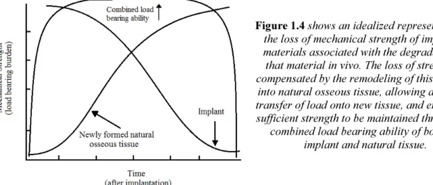
degrades, it allows the ECM to gradually experience greater mechanical loading. The progressive loading from the implant to healing tissues causes many cycles of this remodeling to occur slowly as the scaffold degrades.37,38 This loss of mechanical strength and subsequent transfer of load to the newly formed, natural tissue in an idealized scaffold is illustrated in Figure 1.4.35 This ensures the delicate new tissue is not required to support full physiological load until it has become sufficiently strong, preventing further injury from occurring while the body is still healing.38 This behavior creates a completely natural tissue to replace a damaged one, effectively avoiding many of the negative aspects of allografts and permanent implants.
Figure 1.4 shows an idealized representation of the loss of mechanical strength of implanted materials associated with the degradation of that material in vivo. The loss of strength is compensated by the remodeling of this material
into natural osseous tissue, allowing a gradual transfer of load onto new tissue, and ensuring a sufficient strength to be maintained through the
combined load bearing ability of both the implant and natural tissue.
13 1.4 Hydroxyapatite-Gelatin Composite Materials
In response to the need for new bone replacement materials, Ko et al. created a novel bioceramic by blending hydroxyapatite with gelatin, forming a composite referred to as HAp-Gel.43. Rather than utilizing collagen (specifically type-1 collagen) as the organic phase of this composite, as is seen in bone, HAp-Gel uses the hydrolyzed form of collagen known as gelatin. This replacement had profound implications on the composite. On one hand, gelatin is a cheaper alternative than collagen, making this an attractive material to study in terms of making biomaterials accessible to a wider range of patients. Additionally its properties show lower batch to batch variation than collagen. Because of the hydrolysis of collagen to gelatin, purification and processing have less impact on the final structure. Alternatively, this material loses much of toughening associated with collagen, as the hierarchical structure of bone is not maintained during HAp-Gel processing. However, a substantial mechanical binding is present. It was observed that as the carboxylate groups of gelatin are responsible for HAp nucleation and growth, maintaining some degree of robust mechanical properties required for these implants.43
14
sufficiently strong materials when porous.44,45 Unfortunately, greater strength in these composites was shown to be related to increasing GA content, however, increasing GA content was also shown to decrease cell viability. The need for these materials to maintain sufficient mechanical properties when porous is an important consideration for potential scaffolding materials. Without this porous architecture, cells are unable to interpenetrate and ultimately remodel the scaffold, making these materials useless for tissue engineering applications. Though good initial results were obtained, demonstrating the promise of HAp-Gel based materials, the negative results also highlighted the need to investigate new cross-linking chemistries.
Problems with HAp-Gel/GA samples were ultimately improved by incorporation of a different cross-linking agent (N, N’-bis [(3-trimethoxysilyl)propyl]ethylene diamine, commonly referred to as (enTMOS).46 This cross-linker utilizes a common sol-gel process, the condensation polymerization of trialkoxysilanes, which yields a bioactive glass, which is demonstrated in
Figure 1.5.
Figure 1.5Hydrolysis condensation reaction leading to cross-linked sol-gel materials.
15
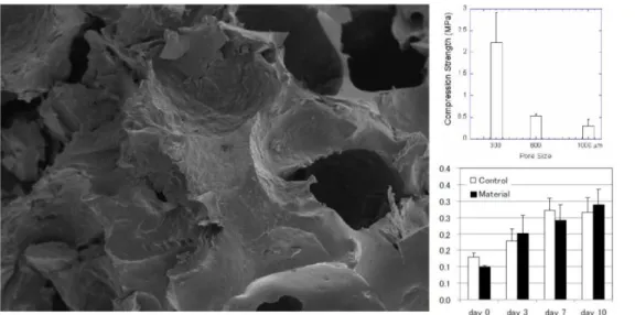
ability of enTMOS Si-O bonds to interact with PO43- present in HAp-Gel. Furthermore, the amines on enTMOS were observed to hydrogen bond with carboxylate groups on gelatin, further strengthening this interaction. HAp-Gemosil also had numerous other advantages over previous HAp-Gel based materials, including faster setting time, better processability when wet, better stability after setting, and the ability to fill arbitrary shapes. This last property is especially important when trying to reconstruct bony defects, such as those caused by cancer or other non-traumatic bone injuries. Furthermore, it demonstrated excellent compressive strength, and also the ability to form a porous material through the use of salt-leaching techniques. Salt-leaching was shown to effectively yield HAp-Gemosil materials with tunable pore size, though pore size was shown to be inversely proportional to mechanical strength. This material proved to be an excellent substrate for the spreading and proliferation of MC3T3-E1 preosteoblasts. These cells were shown to migrate into and spread out over the material, suggesting a favorable substrate for cellular interaction. Furthermore, alkaline phosphatase activity assays also showed that these materials also did not hinder metabolic activity or differentiation of plated preosteoblasts.45,46 These results are shown in Figure 1.6.
Figure 1.6 (Left) SEM image of porous
HAp-Gemosil Material, (Upper right) Strength related to pore size and
(Lower right) ALP activity on porous
16
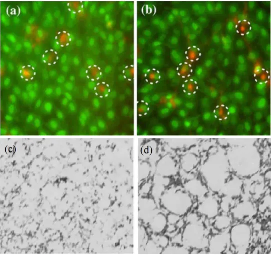
This material also demonstrated signs of osteoconductivity. Alizarin red stains were used to demonstrate mineralization patterns in vitro, as shown in Figure 1.7. In these studies, it can clearly be seen that cells plated on HAp-Gemosil samples were observed to create mineralization patterns that are similar to those observed in trabecular bone. The pattern observed for the control sample saw a relatively homogeneous dispersion of spots with no clear connectivity between the spots. The patterned formation on the Gemosil plates is reminiscent of a 2-D construct of osseous tissue, and it was observed that osteoblasts were found to spread over the interconnected mineralized pattern, with no cells observed between the network. This is in contrast to the control group which showed cells covering over the entire surface. This implies as the HAp-Gemosil component degrades, it could be remodeled by osteoblasts into an interconnected network similar to natural bone. The combination of these properties, plus the relative ease of processing and low cost of HAp-Gemosil materials made this an excellent potential scaffold material for further studies.
17
Figure 1.7 Viability assays(a-b) and mineralization studies(c-d) of osteoblast plated on control and HAp-Gemosil. Control samples showed good cell viability (a) but no clear remodeling behavior (c) contrasting
with Gemosil showing similar viability (b) and also signs of preliminary remodelling (d)
in this way; negative side effects of potentially toxic byproducts and long term stability of the implant are both avoided.
18
materials. Based on this rationale, it can be seen that the one thing all of these previous composites lacked was a suitable mimic for the collagen found in natural bone. This is an important component of the composite as a substantial amount of bone’s toughness comes from collagen being mineralized within the HAp matrix as it grows.3 So it naturally follows that it is possible to incorporate polymers into these HAp-Gel composites to mimic the role of collagen that is not preserved when gelatin is substituted for collagen. In the above examples, all of the cross-linkers (e.g. enTMOS, GA) used were utilized in order to maximize short range interactions in the composite, allowing for improved mechanical strength. By mimicking collagen with a synthetic polymer, these composites can benefit from additional long range interaction. This allows distant portions of the composite to connect physically and chemically, which is vital for improving flexural strength and toughening a composite by helping to delocalize stress throughout a larger area of the material and prevent damage.
As mentioned previously, polymers on their own are not well suited for orthopedic scaffolding applications due to their low mechanical strength. However, extensive work has been done blending polymers with various inorganic materials,14,39 and this approach has been shown to improve the performance of these biocomposites by altering their degradation profiles and softening these high modulus materials.10,11 Synthetic polyesters such as poly(lactic acid) (PLLA),9,47,48 poly(glycolic acid) (PLGA)49, poly(
19
to be isolated and optimized in order to maximize toughness of a composite.49,51 This optimization can come from choice of monomers, type of architecture (i.e. diblock, triblock, random, alternating) molecular weight, and final material processing (e.g. braided fibers, sintered bulk material etc.) Therefore, copolymers present a useful way to tune the properties of biocomposites such as crystallinity, glass transition temperature (Tg), modulus, degradation behavior and mechanical strength, all of which can be specifically optimized for use in preparing scaffolds. 51,54
20 REFERENCES
(1) Ray, N. F.; Chan, J. K.; Thamer, M.; Melton, L. J. Journal of Bone and Mineral Research1997, 12, 24-35.
(2) Field, R. A.; Riley, M. L.; Mello, F. C.; Corbridge, J. H.; Kotula, A. W. J. Anim Sci.1974, 39, 493-499.
(3) Lakes, R. S. Nature1993, 361, 4.
(4) Friedlaender GE, G. V. AAOS Workshop1991, 6-8.
(5) Guha SC, P. M. British Journal of Plastic Surgery1983, 36, 305-6. (6) Coventry MB, T. E. Journal of Bone and Joint Surgery1972, 54, 83-101. (7) Banwart, J. C.; Asher, M. A.; Hassanein, R. S. Spine1995, 20, 1055-1060. (8) Keller EE, T. W. Journal of Oral and Maxillofacial Surgery1987, 45, 11-14. (9) Roether, J. A.; Boccaccini, A. R.; Hench, L. L.; Maquet, V.; Gautier, S.; Jérôme, R. Biomaterials2002, 23, 3871-3878.
(10) Middleton, J. C.; Tipton, A. J. Biomaterials2000, 21, 2335-2346.
(11) Puppi, D.; Chiellini, F.; Piras, A. M.; Chiellini, E. Progress in Polymer Science 2010, 35, 403-440.
(12) Shoichet, M. S. Macromolecules2009, 43, 581-591.
(13) Zhou, Y.; Hutmacher, D. W.; Varawan, S.-L.; Lim, T. M. Polymer International 2007, 56, 333-342.
(14) Deng, X.; Hao, J.; Wang, C. Biomaterials2001, 22, 2867-2873.
(15) Durucan, C.; Brown, P. W. Advanced Engineering Materials2001, 3, 227-231. (16) Wiles, P. British Journal of Surgery1953, 45, 488.
(17) Hulbert, S. F. Y., F.A; Matthews, R.S. Journal of Biomedical Materials Research 1970, 4, 433-456.
(18) Akeson, W. H.; Woo, S. L. Y.; Rutherford, L.; Coutts, R. D.; Gonsalves, M.; Amiel, D. Acta Orthopaedica1976, 47, 241-249.
21
(20) Bergsma, J. E.; de Bruijn, W. C.; Rozema, F. R.; Bos, R. R. M.; Boering, G. Biomaterials1995, 16, 25-31.
(21) Bodén, H.; Adolphson, P.; Öberg, M. Archives of Orthopaedic and Trauma Surgery2004, 124, 382-392.
(22) Venesmaa, P. K.; Kröger, H. P. J.; Miettinen, H. J. A.; Jurvelin, J. S.; Suomalainen, O. T.; Alhava, E. M. Journal of Bone and Mineral Research 2001, 16, 2126-2131.
(23) Teoh, S. H. International Journal of Fatigue2000, 22, 825-837. (24) H.W.J. Huiskes, B. v. R. Clin. Orthop.1992, 274, 10.
(25) Frost, H. The Angle Orthodontist1994, 64, 175-188.
(26) H.W.J. Huiskes, H. W., B. van Rietbergen, Clin. Orthop.1992, 274, 10. (27) Eckhardt, A. A., H Arch Orthop Trauma Surg2003, 123, 28-35.
(28) Bobyn, J. D. W., G.C Clinical Orthopaedics and Related Research® 1980, 150, 263-270.
(29) Radin SR, D. P. J Biomed Mater Res.1994, 28, 1303-9.
(30) Bauer, T. W. S., S Clinical Orthopaedics and Related Research® 2002, 395, 11-22.
(31) Hench, L. L. Journal of the American Ceramic Society1991, 74, 1487-1510. (32) Rezwan, K.; Chen, Q. Z.; Blaker, J. J.; Boccaccini, A. R. Biomaterials 2006, 27, 3413-3431.
(33) Imam Khasim, H. R.; Henning, S.; Michler, G. H.; Brand, J. Macromolecular Symposia2010, 294, 144-152.
(34) Langer, R. V., J.P. Science1993, 260, 920-926.
(35) Raghunath, J.; Rollo, J.; Sales, K. M.; Butler, P. E.; Seifalian, A. M. Biotechnol Appl Biochem2007, 46, 73-84.
22
(38) B. van Rietbergen, H. W. J. H., H. Weinans, D.R. Sumner, T.M. Turner, J.O. Galante J. Biomech1993, 26, 13.
(39) Bucholz, R. C. A. H. R. Orthop Clin North Am1987, 18, 323-34.
(40) Shokrollahi, P.; Mirzadeh, H.; Scherman, O. A.; Huck, W. T. S. Journal of Biomedical Materials Research Part A2010, 95A, 209-221.
(41) Tas, A. J. Mater. Sci: Mater Med2008, 19, 2231-2239.
(42) Ishihara K, A. H., Nakabayashi N, Morita S, Furaya K J Biomed Mater Res.1992, 26, 937-45.
(43) Chang, M. C.; Ko, C.-C.; Douglas, W. H. Biomaterials2003, 24, 2853-2862. (44) Ko CC, O. M., Fallgatter AM, Hu W-S. J. Material Research2006, 21, 8.
(45) Chiu, C.-K. F., Joao; Luo, TJ M.; Ko, Ching-Chang J Mater Sci: Mater Med 2012, 23, 2115-2126.
(46) Luo, T.-J.; Ko, C.-C.; Chiu, C.-K.; Llyod, J.; Huh, U. Journal of Sol-Gel Science and Technology2010, 53, 459-465.
(47) Oh, J. K. Soft Matter2011, 7, 5096-5108.
(48) Declercq, H.; Cornelissen, M.; Gorskiy, T.; Schacht, E. Journal of Materials Science: Materials in Medicine2006, 17, 113-122.
(49) Jiang, T.; Nukavarapu, S. P.; Deng, M.; Jabbarzadeh, E.; Kofron, M. D.; Doty, S. B.; Abdel-Fattah, W. I.; Laurencin, C. T. Acta Biomaterialia2010, 6, 3457-3470.
(50) Bat, E.; van Kooten, T. G.; Feijen, J.; Grijpma, D. W. Macromolecular Bioscience 2011, 11, 952-961.
(51) Bat, E.; Plantinga, J. e. A.; Harmsen, M. C.; van Luyn, M. J. A.; Zhang, Z.; Grijpma, D. W.; Feijen, J. Biomacromolecules2008, 9, 3208-3215.
(52) Andronova, N.; Albertsson, A.-C. Biomacromolecules2006, 7, 1489-1495.
(53) Dargaville, B. L.; Vaquette, C.; Peng, H.; Rasoul, F.; Chau, Y. Q.; Cooper-White, J. J.; Campbell, J. H.; Whittaker, A. K. Biomacromolecules2011, 12, 3856-3869.
Adapted with permission from the Journal of Materials Chemistry 2012, 22, 22888, by Jason Dyke, Kelly Knight, Huaxing Zhou, Chi-Kai Chiu, Ching-Chang Ko, and Wei You
23
CHAPTER 2: PERFORMANCE OF BIOCERAMIC COMPOSITES CONTAINING POLY(L-LACTIDE-CO-PROPARGYL CARBONATE)-G-AZIDO SILANE
2.1. Introduction to Polymer Bioceramic composites
Natural bone is a lightweight mineral composite consisting of inorganic apatite, mainly hydroxyapatite (HAp), within a dense matrix of organic collagens. The long fibrous collagen makes the normally brittle HAp more resilient, helping to improve flexural strength in natural bone.1 The hierarchy HAp-collagen structure, however, cannot be reproduced easily using engineering principles. Sequentially, autografts (tissues from the host) have become the gold standard for replacement of damaged tissues.
Due to the drawbacks (e.g., donor site morbidity, shortage of resources) of autografts, the need for alternate alloplastic materials is clear. Orthopedic biomaterials, in particular, have been heavily studied, and comprehensively reviewed by Puppi2 and Shoichet3 in greater detail. In particular, significant progress has been achieved in engineering materials capable of degrading
in vivo, either by hydrolytic or enzymatic activity to promote formation of natural osseous tissue, through growth of tissue into the composite material.4
25
In response to the needs, several classes of biocompatible and biodegradable polymers have been established for numerous medical applications. Polyesters such as poly(lactic acid) (PLLA)7-9, poly(glycolic acid) (PLGA)10, poly(
ε-caprolactone) (PCL)11,12 and poly(trimethylene carbonate) (PTMC)13-15 have been investigated as native or as in blends16,17 for a variety of medical applications. Each of these polymers has unique mechanical and degradative properties allowing them to be utilized in a wide range of biomaterials.2,3,18-21 Though homopolymers have good properties for in vivo applications, they are often limited by their diversity in function. Therefore, copolymers present a useful way to obtain tunable properties such as molecular weight, crystallinity, glass transition temperature (Tg), modulus, degradation behavior and tensile strength, all of which can be specifically optimized for use in preparing scaffolds.10,13 Furthermore, the structure of many of these monomers can be synthetically altered to tailor their properties. These monomers can be combined in nearly endless ways to form functional materials with application specific properties. Because of this, it is important for synthetic chemists to formulate new monomers and design new monomers and polymers in an attempt to improve the utility of materials engineered for specific applications.
26
siloxane (HAp-Gemosil) composite. This helps give additional structural support to the composite and can help impart the network strength of the silane matrix into the composite, leading to enhanced mechanical properties and molding ability. While this matrix did improve the compressive strength and processability of the composite, the short chain siloxane based matrix was brittle and still susceptible to tensile failure. It was clear that a more robust composite was needed in order to further advance this system for potential scaffolding applications. One possible solution is to design and incorporate a biocompatible and cross-linkable polymer of sufficient chain length into the composite.
27
controlled. More importantly, cyclic carbonates can be easily derived34 and the modifications present on PC would allow the incorporation of a pendant silane graft monomers onto the polymer backbone (vide infra), while also imparting similar properties to PTMC.
Second, we designed the chosen copolymer to cross-link within the HAp-Gemosil composite because this would lead to improved tensile strength via better long range interaction when compared with physically blending polymer into the composites. Specifically, this approach – designing polymers with cross-linkable grafts – would provide two advantages: (a) increase interfacial adhesion over polymer blends, and (b) enhance long range interactions when compared with composites that are only cross-linked by small molecules (e.g., enTMOS). Consequently, the composite would more effectively mimic the short and long range chemical interactions seen within bone, thereby improving tensile strength of the composite.35 This should in turn help to resist tensile loading by distributing forces more evenly through the composite, rather than at the point of application.36 Since HAp-Gemosil composites were originally cross-linked using an amino-silane (enTMOS), it would be ideal to design the copolymer to bear a similar cross-linkable silane group.
28
CuAAC chemistry. This post-polymerization functionalization approach allows the grafting of the silane functionality to occur after polymerization, ensuring the fidelity of the silane groups is maintained. P(LLA-co-PC)(AS) can then be blended with HAp-Gel and cross-linked in the presence of enTMOS to produce a fully cross-linked composite through hydrolysis–condensation of trialkoxysilyl groups present on both the copolymer and enTMOS. Such programmed composite would improve adhesion through coordination of grafted amide and triazole groups to free carboxylate groups on gelatin and also through silane cross-linking to HAp.
cross-29
linking agents possess merit for future study in expanding their applications for bioceramic composites.
2.2 Monomer and Cross-Linker Synthesis
The hydrolysable cyclic TMC inspired carbonate monomer, propargyl carbonate (PC), was synthesized in good yield over four steps from established methods39 as shown in
Figure 2.1.
Figure 2.1 Synthesis of PC monomer from 1,1,1-Tris(hydroxyl methyl)ethane (THME)
30
Figure 2.2 Synthesis of enTMOS inspired, azido-silane graft monomer (AS)
2.3 Synthesis and Characterization of Copolymers from Sn(Oct)2 Catalyzed ROP
31
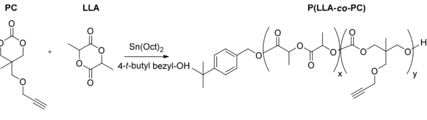
Figure 2.3 Ring-opening copolymerization of L-Lactide (LLA) and the TMC derivative monomer, Propargyl Carbonate (PC)
32
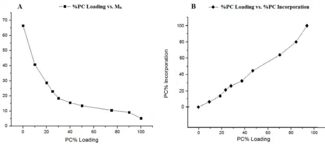
Figure 2.4. Copolymerization behavior of LLA-PC Ring Opening Polymerizations (A) Polymer molecular weight (Mn) as a function of increasing %PC load. (B) %PC present in the polymer chain as a
function of mol fraction loaded before polymerization.
However, at these elevated temperatures and reaction times, PLLA segments could thermally degrade more readily than polycarbonate segments.30 In our cases, LLA is consumed faster than PC, resulting in a portion of PC monomers not being incorporated into the copolymer chain in the chosen reaction time (20 h). Instead, these unconsumed PC monomers form low molecular weight (MW) chains (2 – 4 kDa) consisting primarily of poly-propargyl carbonate, or remain as unreacted PC monomer. Due to the low MW and rubbery nature of PC, both remain soluble in methanol and are washed away during precipitation.
33
increases, this methine signal begins to split, with a second peak appearing at δ = 5.02 ppm (proton b in Figure 2.5B). This secondary methine peak arises as a result of inductive effects on those methine peaks that neighbor a carbonate unit. These protons would feel a weaker de-shielding effect due to the lower electron withdrawing nature of the carbonate when compared with the ester in LLA, and thus will be shifted slightly upfield. This effect is observed only in LLA methine protons that are adjacent to a carbonate in the copolymer. During the copolymerization, if a propagating polymer chain end belongs to a lactide monomer and this “lactide” chain end opens up another lactide monomer, then all methine peaks are equivalent and no alternate shift is observed. When the propagating “lactide” chain end attacks a carbonate
Figure 2.5(A) NMR spectra for PLLA and PPC homopolymers, as well as a 44.6% PC Containing P(LLA-co-PC) copolymer, illustrating the rise of a secondary methane peak, indicating a statistically
34
however, the additional oxygen on newly incorporated carbonate carbonyl helps slightly shield the α-methine proton that is next to the carbonate and leads to the appearance of a second peak upfield of the first (Figure 2A). This splitting effect is highlighted in Figure 2B. The relative ratio of these methine protons at different chemical shifts (5.18 ppm vs. 5.02 ppm) gradually decreases as the mol % PC increases in the copolymer, indicating the statistically “random” nature of the copolymerization. A summary of polymer composition is given below in
Table 2.1.
An important implication of employing the copolymer of LLA and PC is to lower the Tg of the copolymer. PLLA is below its Tg at the physiological temperature and the incorporation of PC into its backbone can help reduce crystallinity and lower the Tg of the resultant copolymer.
Table 2.1. Summarized polymerization data for P(LLA-co-PC) copolymers.
PC Loading
(%PC)
a%PC
Incorporation
bM
n(kDa)
cM
w(kDa)
0
0
66.7
93.7
10
6.4
53.0
57.8
20
13.5
28.7
46.6
25
21.05
23.0
35.8
30
25.9
18.6
33.5
40
32.1
15.5
23.3
50
44.6
13.5
22.6
75
64.1
10.5
12.4
90
80
9.1
11.3
100
100
5.2
9.4
a
Copoymers of LLA and PC, denote by the % loading of PC during polymerization
b
Incorporation measured by H1 NMR
c
35
This provides a route for altering the crystallinity and helping to make the copolymer less brittle.
This will allow for improved mechanical properties to be observed under physiological
conditions and in turn, helping to raise flexural strength of future composites in vivo.31,40 To
demonstrate the impact on the Tg of the copolymer by the introduction of PC into PLLA, DSC
traces of three polymers with different mol% incorporation of PC were obtained and compared
(Figure 2.6).
It is clearly observed that the Tg decreases with the increased PC content. Specifically,
the Tg drops from 57.9 ºC for PLLA, to 53.7 ºC for P(LLA-co-PC)(AS)6.4%, and finally to 52.8
ºC for P(LLA-co-PC)(AS)21%. The amorphous nature of the PC monomer helps to influence Tg
by altering chain rigidity and hindering the chain’s ability to pack effectively.
Figure 2.6 DSC Traces and physical appearance of polymers. Left: Images of several polymers to
demonstrate changes in physical appearance caused by changes in polymer chain length and distribution. Right: DSC traces for three of these polymers are given to demonstrate the tunability of Tg as a function
36
Since both the HAp and enTMOS portions of the composite are very brittle, addition of a rubbery copolymer can help improve polymer tensile strength by increasing flexibility and elongation at break within the composite.14
PLLA and high PLLA content polymers appear as white fibrous solids at room temperature (0 – 10% PC incorporation) due to the high LLA content. As the mol% PC increases in the polymer, MW decreases and polymers becomes slightly more yellow in appearance, less fibrous and softer. Above 50 mol% PC incorporation, the polymers appear as viscous yellow/orange liquids. These polymers are largely amorphous due to the high PC content in the backbone, which serves to add steric bulk, reduce symmetry, and lower rigidity when compared with LLA segments. The short chain length of these polymers also obstructs effective packing and crystallization of adjacent chains. Examples of the physical appearance of several polymers are also given in Figure 3 for reference.
2.4 Post-Polymerization CuAAC Click Functionalization and Amalgamation
After determining that PC can successfully copolymerize with LLA to give polymers with controlled composition and properties, it was important to functionalize the pendant acetylene of PC to help understand how this functionalized polymer can be processed into HAp-Gemosil composites. CuAAC (a “Click” reaction) allows nearly quantitative coupling of terminal azides to alkynes via Cu(I) catalysis, with few byproducts and little purification needed.41 This approach was attempted for several PC functionalized copolymers and coupling was observed to be successful.10,42 This reaction is highlighted in
37
Figure 2.7 Post-polymerization functionalization of P(LLA-co-PC) with AS via CuAAC “Click” reaction
38
enTMOS. This multiple crosslinking via enTMOS creates a fully linked gel which can be easily formed and allows for chemical linking of polymer to HAp-Gel to enTMOS, increasing long range adhesion and strength. This composite formation and subsequent sol-gel condensation between enTMOS and AS is highlighted in Figure 2.8.
Figure 2.8Illustration of amalgamation with HAp-Gel and condensation reactions with enTMOS leading to fully set composite
After successfully forming these new composites with our designed copolymers incorporated, it was important to see how these newly formed P(LLA-co-PC)(AS) composites compared to other previously tested materials. To this end, we carried out the cellular and mechanical studies to determine the effect that polymer blending has on composites when compared with previously studied HAp-Gemosil samples. Figure 2.9 presents the results of the 21 day MTS assay, It can be seen from these data that, when compared with the control sample, both previous HAp-Gemosil and new HAp-Gemosil/P(LLA-co-PC)(AS) composites showed similar biocompatibility over a 21 day period. Furthermore, the resultant growth curves of MC3T3-E1 cells were similar for all three groups. Cells grew up to 7 days and, then, leveled out. This indicates proliferation of cells until reaching they are able to saturate the material. At this point, the number of cells stays relatively constant, demonstrating no substantial leaching of
O O O O O O O O H O N NN H N
(MeO)3Si
O
P(LLA-co-PC)(AS)
39
0
0.5
1
1.5
1
7
21
No Mat Gemosil Polymer
Days
toxic materials out of the composite over the 21 day time interval. There were no differences in absorbance between the materials and the control, showing no difference in cell viability among the tested substrates.
Figure 2.9 MTS Assay of Control compared to HAp-Gel and HAp-HAp-Gel-
P(LLA-co-PC)AS 13.5% Composites showingcell viability. Cells were plated in 96 well plates
and viability was measured by formazan absorbance at
Days 1, 7, and 21
These data suggest that the incorporation of P(LLA-co-PC)(AS) had little to no negative effect on the biocompatibility of HAp-Gemosil composites, and that both materials behaved quite similarly to the control samples with no plated material.
40 0 30 60 Polymer Gemosil F le x u ra l St re n g th ( M Pa ) HAp-Gemosil
Biaxial Flexure Strength
strength of nearly 40% compared to HAp-Gemosil composites. On average, flexural strength of HAp-Gemosil
(41± 9 MPa) increased for HAp-Gemosil/P(LLA-co-PC)(AS) (58± 14 MPa).
Figure 2.10 Changes in biaxial flexure strength between HAp-Gemosil and HAp-Gemosil doped with
P(LLA-co-PC)AS13.5% co polymers.
The stiffness of the force-displacement curve recorded from the biaxial bending test did not differ (P=0.08) between the original (2.06 N/mm) and the new (2.15 N/mm) composites. In our in-house data, the HAp-Gemosil had a compressive modulus around 862±129 MPa and a reduced modulus 18.0±4.9 GPa measured by the nanoindentation tester (Hysitron Inc.) Based on the stiffness data, we expect that the new composite might have similar modulus values although future tests are required.
41
consequences when dealing with this HAp-Gemosil/P(LLA-co-PC)(AS) bioceramic composite. Primarily, this limitation can influence reproducibility and utility of composites like those tested in this study. The use of a second, less polar solvent (acetone) during blending helped improve composite formation, making it possible to study the interaction of this polymer within HAp-Gemosil composites. Unfortunately, the use of organic solvents removes our ability to dope this composite with cells for scaffolding applications, and these processing issues hinder the ability to study composite interactions in vivo. Furthermore, this second solvent helped blend phases during processing, but ultimately did not solve all problems associated with blending a hydrophobic inorganic ceramic (HAp-Gel) with a hydrophilic polymer phase (P(LLA-co -PC)(AS). This mismatch manifested itself in displaying poor interfacial adhesion between components. Although this was still able to provide considerable fiber bridging and improved flexural strength, it led to a large decrease in compressive strength when compared to HAp-Gemosil, showing in Figure 2.11.Though HAp-Gemosil did not possess the compressive
strength of natural bone, it was sufficiently close for consideration.
Figure 2.11 Changes in compressive strength observed between
Gemosil and HAp-Gemosil doped with polymer, compared to natural cortical bone.
Human Bone HAp-Gemosil Polymer
0 40 80 120 C o m p re s s iv e S tr e n g th ( M P a
42
However, the large decrease seen in polymer doped samples makes it insufficient for consideration as a load bearing material for orthopedic applications, further complicating this materials ability to be used for potential scaffolding applications.
Despite the drawbacks, this system still showed merit in improving some properties of HAp-Gemosil composites, while preserving their biocompatibility. Improvements in cross-linking chemistry are required to allow for better processability and material performance. These improvements would allow this system to be more rigorously studied in vivo to determine the efficacy of this polymer/ceramic system for future scaffolding applications.
2.5. Conclusions
In summary, we have synthesized a derivatized TMC monomer, PC, which is capable of undergoing ROP with L-Lactide to afford copolymers with tunable MW, mol % PC incorporation and Tg. The ability of these monomers to copolymerize and yield potentially biodegradable and biocompatible polymers of tunable properties makes this an attractive system for biological applications. In the current demonstration, we coupled the copolymer with AS graft agents inspired by enTMOS, converting the copolymer into “cross-linkable” via these pendant silane groups. After being processed into the original HAp-Gemosil cement composite facilitated by the amino-silane enTMOS, these AS functionalized polymers were capable of bridging the new composite and providing enhanced long range adhesion, while still maintaining the biocompatibility of the new composite.
43
coupling, which could lead to the possibility of increased cell morbidity. Furthermore, the premature cross-linking could contribute to an inability of these polymers to fully cross-link into the enTMOS silsesquioxane matrix, leading to poor adhesion between the hydrophobic polymer and the hydrophilic HAp-Gel moieties in the composite. Therefore, further work remains to be done, especially regarding the graft monomer and cross-linking. Fortunately, the PC monomer introduces a pendant acetylene group on the copolymer, which provides a synthetic handle for post-polymerization modification to give more synthetic freedom. This ‘acetylene handle’ allows various pendant groups to be attached to the copolymer, thus one can further alter the composite properties to obtain unique, applications specific properties. Future composites will be synthesized using similar P(LLA-co-PC) polymers as the chemistry and properties of these copolymers have been elucidated in this study, but emphasis will be placed on utilizing alternate “click” reactions which can preclude the use of potentially toxic catalysis. Alternate graft monomers will also be investigated to determine a method for cross-linking which can be easily degraded. This will eliminate potential problems caused by residual material left after degradation. Additionally, a less sensitive method of cross-linking would be ideal as to allow better control of cross-linking reactions and thereby improve processing of the final composite. If these issues can be sufficiently addressed, this HAp-Gemosil-P(LLA-co-PC)(AS) copolymer system will provide a new springboard to undertake further scaffolding composite work.
2.6 Experimental Details General Methods
44
distillation using a Büchi rotary evaporator at water aspirator pressure (< 20 torr) followed by removal of residual volatile materials under high vacuum (< 1 torr). The term “high vacuum” refers to vacuum achieved by a standard belt-drive oil pump (< 1 torr).
1H and 13C NMR spectra were recorded on Bruker AC-400 (400 MHz) spectrometers.
Chemical shifts are reported in parts per million (ppm) relative to residual solvent peaks (CHCl3: 1H: d 7.26). Peak multiplicity is reported as: singlet (s), doublet (d), triplet (t), quartet (q), multiplet (m), and broad (br).
Materials
Ethyl chloroformate (99%) and CaH2 (60% in mineral oil), and 4-tert butyl benzyl alcohol (98%) were obtained from Acros Organic and used as received. 1,1,1-Tris(hydroxyl methyl)ethane (THME, 99%), triethylamine (TEA, 99%), 5-bromovaleryl chloride (98%) and CuBr (98%) were obtained from Alfa Aesar and used as received. Benzaldehyde (Aldrich 98%),
p-toluene sulfonic acid (TsOH, Aldrich, 98.5%), (N, N’-bis [(3-trimethoxysilyl)propyl]ethylene diamine (enTMOS, 95% in MeOH, Gelest), tin(II) 2-ethyl hexanoate (SnOct2 98% MP Biomedicals), propargyl bromide (80% in toluene, TCI) and 3-aminopropyl trimethoxy silane (96% TCI) were used as received. L-Lactide was generously donated by Purac and used without further purification. Hexanes, acetone, chloroform, dichloromethane (DCM), anhydrous toluene, anhydrous methanol (MeOH), ethyl acetate and tetrahydrofuran (THF) were obtained from Fisher. THF was freshly distilled over sodium before use.
Synthesis of (Propargyl Carbonate (PC)) Monomer
45
temperature. To this stirring solution, benzaldehyde (23.2 mL, 0.23 mmol) was added dropwise and allowed to react for 16 hours. The reaction was then neutralized with aqueous ammonia and concentrated by rotary evaporation. The product was then dissolved in DCM and washed 3 times with water before again concentrating under rotary evaporation to yield 39 g (94%) of C1 as a colorless solid. 1H NMR (400 MHz, CDCl3): δ 0.81 (s, 3H), 3.66 (d,2H), 3.91 (s, 2H), 4.06 (d, 2H), 5.44 (s, 1H), 7.35-7.49 (m, 5H).
C1 (35 g, 168 mmol) in THF (50 mL) were added dropwise to a cold stirring solution of NaH (60% in mineral oil, 12 g, 302 mmol) at 0 ºC to yield a milky white solution. After 30 minutes of cold stirring, the solution was heated on oil bath to 60 ºC for 2 hours, yielding a pale yellow solution. Propargyl bromide (25 g, 211 mmol) was then added dropwise and allowed to stir for 16 hours. This solution was then quenched with water to afford a deep red solution with precipitate. This solution was extracted 3 times with brine and concentrated under high vacuum to yield crude C2 as a red oil.
Crude C2 (12 g, 48.7 mmol) was stirred in 400 mL 1:1 v/v MeOH:1M HCl for 2 hours. 1M NaOH was then used to raise the pH to 7 before MeOH was removed by rotary evaporation. The product was extracted using ethyl acetate to yield crude C3. Purification via flash chromatography using 2:1 ethyl acetate: hexanes yielded 6.1g (54% over 2 steps) C3 as an orange oil. 1H NMR (400 MHz, CDCl3): δ 0.84 (s, 3H), 1.65 (b, 2H) 2.45 (s, 1H) 3.49 (s, 2H) 3.58(d, 2H), 3.67(d, 2H), 4.15(s, 2H)
46
evaporation and then purified via flash chromatography with 2:1 hexanes: ethyl acetate to yield 4.52 g (75%) Propargyl Carbonate (PC). 1H NMR (400 MHz, CDCl3): δ 1.11 (s, 3H) 2.46 (s, 1H), 3.49(s, 2H), 4.07 (d, 2H), 4.17 (s, 2H) 4.33 (d, 2H). 13CNMR (400 MHz, CDCl3) δ 17.26, 32.8, 58.7, 70.66, 73.81, 75.25, 78.83, 148.17
Synthesis of Graft Monomer: 5-azido-N-(3-(trimethoxysilyl) propyl) pentanamide (AS)
Synthesis of AS is shown in Figure 2.2. To a dry flask, (3-aminopropyl)trimethoxysilane (1.44 g, 8 mmol) were dissolved in THF with TEA (1 g, 10 mmol) and set to stir (clear solution). 5-bromovaleryl chloride (2 g, 10 mmol) was then added dropwise, forming a white precipitate. This solution was allowed to react for 16 hours under argon. The solution was subsequently filtered to remove the salt and concentrated by rotary evaporation to yield 2.73 g (99%) G1 without further purification. 1H NMR (400 MHz, CDCl3): δ 0.65 (q, 2H), 1.63 (p, 2H), 1.80 (m, 4H), 2.19 (t, 2H), 3.24 (t, 2H) 3.4 (t, 2H), 3.57 (s, 9H), 5.65 (b,1H)
G1 (2.73 g, 8 mmol) was then dissolved in anhydrous DMF and added to NaN3 under dry conditions. This was allowed to react for 16 hours under argon atmosphere. DMF was then removed under vacuum for 36 hours before dry EtOAc was used to extract AS and the compound was again concentrated to yield pure AS 2.4 g (98%) which was stored under dry conditions in a glovebox. 1H NMR (400 MHz, CDCl3): δ 0.65 (t, 2H), 1.78 (m, 6H), 2.19 (t, 2H), 3.26 (m, 4H), 3.41 (s, 9H), 5.69 (s, 1H). 13CNMR (400MHz, CDCl3) δ 6.46, 22.68, 22.81, 28.34, 35.83, 41.77, 50.45, 51.09, 172.27
Synthesis of Copolymers by Sn(Oct)2 Catalyzed ROP
stannous-2-47
ethyl hexanoate (Sn(Oct)2) as the catalyst as shown in Figure 2.3. The ratio of monomers to catalyst to initiator was 100:1:1 [M]:[C]:[I] for all polymerizations. The following is a typical synthesis for copolymer with 10 mol% PC loading. In a glovebox under argon atmosphere, LLA (7 g, 48 mmol) and PC (0.884 g, 4.8 mmol) were added to a high pressure flask with 10 mL anhydrous toluene. To this solution, Sn(Oct)2 and 4-tert-butylbenzyl alcohol (0.075 M, 7 mL) were added quickly and the vessel was then sealed. The reaction container was quickly transferred to an oil bath outside of the glovebox and allowed to react for 20 hours before quenching with methanol. The resulting polymer P(LLA-co-PC) was isolated by precipitation into cold MeOH, and further purified by precipitation from the DCM solution of the polymer into cold methanol 3 times. NMR analysis revealed this polymer to contain 6.4 mol% PC in the backbone and thus was denoted as P(LLA-co-PC) 6.4% for clarity.
Characterization of Polymers
48
Post Polymerization Modification of Polymers via CuAAC
CuAAC reactions were performed in anhydrous DMF at room temperature under argon atmosphere. A typical synthesis of P(LLA-co-PC) 6.4% follows. The azide containing linking monomer (AS), was dissolved with P(LLA-co-PC) 6.4% and CuBr in DMF. Load ratios of AS to acetylene groups of the polymer were 1.1:1 (slight excess of AS) and CuBr was loaded at 2 mol%. Elemental copper was added in trace amounts to help stabilize Cu(I) ions in solution. This reaction is allowed to run for 2 hours before precipitation in cold MeOH to yield white powder of AS functionalized polymer P(LLA-co-PC)(AS) 6.4%. Polymers were treated with EDTA prior to precipitation in methanol to help remove excess copper catalyst.
Amalgamation of AS Functionalized Polymer
Composite cement materials were prepared for biaxial flexure and biocompatibility testing using P(LLA-co-PC)(AS)13.5% loaded at 10wt% into the composite A typical composite formation is presented here with 10 wt% copolymer in the composite. HAp-Gel (250 mg), prepared as previously reported25, was mixed with