Sharif University of Technology
Scientia IranicaTransactions B: Mechanical Engineering http://scientiairanica.sharif.edu
Dynamic nite element analysis of shot peening process
of 2618-T61 aluminium alloy
H. Ullah
a, B. Ullah
a,*, A. Rauf
a, and R. Muhammad
b a. Centres of Excellence in Science & Applied Technologies (CESAT), Islamabad, Pakistan.b. Department of Mechanical Engineering, CECOS University of IT and Emerging Sciences, Peshawar, Pakistan. Received 31 October 2017; received in revised form 26 December 2017; accepted 16 April 2018
KEYWORDS Surface treatment; Finite element analysis; Residual stress; Plastic deformation.
Abstract.Shot peening is a surface treatment processes usually used for the improvement of fatigue strength of metallic parts by inducing residual stress eld in them. The experimental evaluation of shot peening parameters is not only very complex but also costly. An attractive alternative is the explicit dynamics Finite Element (FE) analysis having the capability of accurately envisaging the shot peening process parameters using a suitable constitutive model and numerical technique for the material. In this study, ANSYS/LS-DYNA software was used to simulate the impact of steel shots of various sizes on 2618-T61 aluminium alloy plate described with strain rate dependent elasto-plastic material model. The impacts were determined at various incident velocities. The eects of shot velocity and size on the induced compressive residual stress and plastic deformation were investigated. The results demonstrated that increasing the shot velocity and size would lead to increase in plastic deformation of the target. The obtained results were close to the published ones, and the numerical models were capable to capture the patterns of residual stress and plastic deformation experimentally observed in aluminium alloys. The study is quite helpful in determining and selecting optimal shot peening parameters for the surface treatment of aluminium alloy parts.
© 2019 Sharif University of Technology. All rights reserved.
1. Introduction
Shot peening is one of the cold working surface treat-ment processes usually employed to improve the fatigue strength of many critically loaded metallic components in automotive aerospace and power generation indus-tries [1]. Examples of mechanical components normally surface treated by shot peening process are: landing gear components, blades and shafts, gas turbine and compressor discs, springs, connecting rods, gears, and cam shafts [2]. In shot peening process, the surface of the metal part is impacted with small shots (usually
*. Corresponding author.
E-mail address: baseerullah@gmail.com (B. Ullah). doi: 10.24200/sci.2018.5483.1302
made of steel, glass, or ceramic beads) at high veloc-ities, namely from 20 m/s to 100 m/s, which create a small indentation surrounded by plastic and elastic zones. As the shot bounces back, the recovery of elastic zone generates a large compressive residual stress on the target surface [2]. The intersection of these surface indentations develops a uniform compressive layer at the material surface, which squeezes the grain bound-aries of the material surface together. This results in a signicant delay of the fatigue crack initiation, thus improving the fatigue life of the part [3]. In small aero engines, the compressor blade, usually made of aluminium alloys, is subjected to centrifugal loads causing tensile stress in it. Here, the shot peening process is employed to induce compressive residual stress, which diminishes the magnitude of the tensile stress and hence the blade work below its yield limit
with increase in safety factor and fatigue life. In this study, the thin blade is taken as a at plate to evaluate the shot peening process factors for the required level of plastic deformation as well as the residual stress in the real surface treatment process.
In the literature, there exist extensive experimen-tal studies for the assessment of important properties related to the shot peening process, e.g. plastic defor-mation; residual stress distribution; fatigue life; and the eect of shot, target, and process parameters [4-7]. Despite their eectiveness, the experimental techniques suer from several complications related to the cost and time of experimentation in evaluating the eect of each parameter on the surface treatment [8]. In contrast, the numerical simulation technique is computationally economical and very attractive, and in addition, it has the potential for predicting the complex nature of the shot peening during its impact on the target surface. Among the available numerical techniques, the Finite Element Method (FEM) can be used to determine a range of important parameters related to shot peening and its inuence on the residual stress distribution and plastic deformation. Due to its robustness, the FEM is capable of eectively handling the high velocity impact of a shot with the target involving nonlinearities due to the target material as well as contact of sphere with the target employing explicit dynamics solvers. In recent years, with the availability of increased computational power and numerous commercial FE packages, modelling and numerical simulation of the shot peening process has become an increasingly at-tractive alternative to the tedious experimentation on the process. The three-dimensional (3D) numerical simulation of shot impacts was rst proposed by Al-Obaid [9], employing the FEM. Meguid et al. [1,10] investigated the single and multiple shot impacts using three-dimensional FE models, and the inuence of shot size, shape, and velocity as well as material properties of the target on residual stress distribution. Majzoobi et al. [2] developed a 3D model in explicit dynamics LS-DYNA code simulating the shot peening process with multiple shot impacts. Kang et al. [11] developed both 2D and 3D FE models to simulate single and multiple steel shot impacts on an aluminium 2024-T351 target. ElTobgy et al. [12] developed a 3D elasto-plastic FE model to simulate shot impacts on AISI 4340 steel work piece. Although, a substantial number of numerical studies exist in the literature, e.g. [13-19], shot peening is still considered to be a complex process involving multiple parameters which need to be fully investigated in all its magnitudes employing numerical techniques.
This study is focused on the numerical simulation of shot peening process based on the elasto-plastic dy-namic process of shots' impact on an aluminium alloy target. The strain rate dependent and work hardening material behaviour of the target is considered by using
Johnson-Cook plasticity model. To the knowledge of the authors, this is the rst time that the dynamic be-haviour of shot peening process is being elaborated by describing the time histories of force, energy, induced stress, and plastic deformation of shot interaction with the target. Using FE modelling, a parametric study is also conducted to predict the eects of key parameters such as shot velocity and size on the spatial distribution of residual stress and plastic deformation within the metallic target. Simulations also provide a meaningful insight into the behaviour of the target material, which cannot be achieved experimentally. Furthermore, the parameters predicted by the simulations will be used for actual shot peening of thin compressor blades. 2. Finite element analysis
2.1. FE model
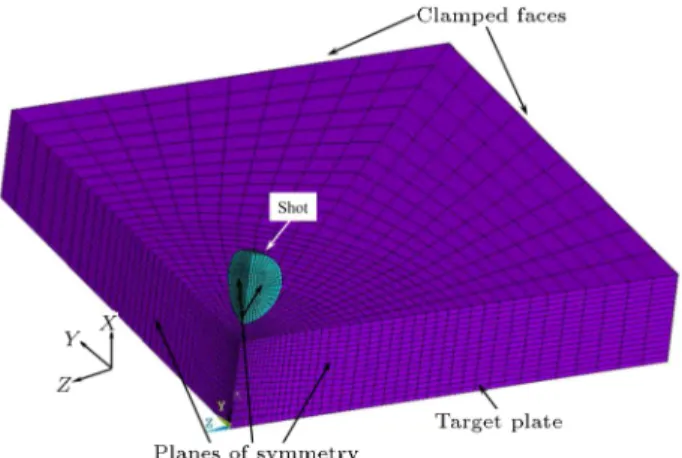
Finite-element 3D models consisting of a target plate and shot were developed in the FE software ANSYS/LS-DYNA 16.0 with explicit algorithm to in-vestigate impact of shot on the target. The dimensions of the target plate of 5 mm 5 mm 0:5 mm were kept constant throughout the simulations, whereas the steel shots used were of diameters 0.4 mm, 1 mm, and 2 mm. Aluminium alloy 2618-T61 based compressor blade/plate was used as a target, because this type of material had better properties over a range of temperatures and its high specic strength and creep resistance made it a better choice for small aero engine applications [20]. The shot was kept tightly close to the target plate to reduce the time of bringing it into contact, thereby enhancing the computational eciency. Figure 1 shows the three-dimensional FE model, where, due to symmetry of the problem, only one quarter portion of the plate as well as shot was modelled, thus further enhancing the computational eciency. Had a circular target plate been considered along with spherical ball, an axisymmetric model would have suced for the problem. Symmetry boundary
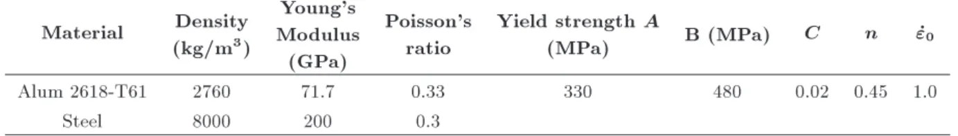
Table 1. Shot and target plate material properties. Material Density
(kg/m3)
Young's Modulus
(GPa)
Poisson's ratio
Yield strength A
(MPa) B (MPa) C n _"0
Alum 2618-T61 2760 71.7 0.33 330 480 0.02 0.45 1.0
Steel 8000 200 0.3
conditions were applied to two planes of XY and XZ in the model. The two outer sides of the rectangular target plate were restrained against displacement and rotations to represent its fully clamped conditions. The base of the target was constrained in the vertical X direction. The shot was free to move only in the vertical direction (X-axis) and was assigned an initial axial velocity in this direction.
In the numerical analyses of shot peening pro-cess [2-4], the target plate is usually dened as a de-formable body and the shot as a rigid body. However, in real-world applications, both the shot and plate behave as deformable bodies. Although stiness of the steel shot is three times greater than that of the target, still it can be treated as a deformable body. Therefore, in the numerical implementation, a multi-body dynamics approach was adopted, which was a standard practice for the simulation of deformable bodies that experienced large deformations during their interaction (contact). Surface-to-surface general contact algorithm (based on penalty method) was used for contact denition between the shot and the target plate, available in LS-DYNA. The nodes on the lower half of the shot surface were selected as contact nodes whereas those on the top surface of the target around the common normal were described as the target nodes (Figure 1). As proposed in [3,10], the coecient of friction used at contact was 0.25.
2.2. Strain rate dependent material model The target material Alum 2618-T61 is subjected to localized plastic deformation at high strain rates of the order of 105s 1in shot peening process [10]. Therefore,
the material constitutive model of the target should be capable to describe not only work hardening of the material, but also the strain rate dependency of the ow stress during its plastic deformation. Such behaviour of metallic materials is widely elucidated by Johnson-Cook [21] model given as:
=A + B"n
p 1+C ln _"_"p 0
1
T T0
Tmelt T0
m
; (1) where "p is equivalent plastic strain; _"p and _"0 are
the applied and reference strain rates; T is applied temperature, T0 reference temperature, and Tmelt
melting temperature; A is initial yield strength of the material; B is work hardening modulus; n is exponent;
and C and m are constants describing the ow stress dependency on strain rate and temperature. In the present simulations, the thermal eects are neglected, because the shot peening is usually considered as a cold working process [16]. Parameters of Johnson-Cook model are evaluated through experimental testing of material at high strain rates [22]. In this study, initially, the parameters were selected from the liter-ature for aluminium alloys [23]. However, in the nal simulations, the constants A, B, and n were calibrated numerically by obtaining a close t between numerical and experimental true stress-strain curves. The rate dependent properties were taken from the literature for similar material. Steel shot was modelled as linear elastic material. Table 1 shows material properties for both the target and shot.
2.3. Discretisation, mesh sensitivity, and dynamic solution technique
The 8-noded linear solid 164 hexahedron element specic to explicit dynamics analyses was used for meshing both the shot and target plate. The el-ement had degrees of freedom of translations, ve-locities, and accelerations at each node in all three directions [24]. Furthermore, the element was dened with reduced integration and viscous hourglass control options. Reduced integration is benecial in saving the computational time in cases of high nonlinearities. In addition, these qualities provide the capability of controlling hourglass and eliminating the occurrence of shear locking in problems in which the bending eect is dominant. Lagrangian formulation option was selected to elucidate the material as a continuum.
Three dierent FE models were developed for achieving mesh convergence using dierent mesh sizes in the plane as well as depth of the target plate. A biased meshing scheme was adopted with ner mesh at the shot impact location on the target top surface. This biasing was also dened along the plate depth with ner mesh at the top and coarser at the bottom. FE models with three meshes, I, II, and III, resulted in 3168, 11840, and 32256 elements, respectively. The shot mesh size was kept the same in all the models. These models were solved for 10 s with impact velocity of 50 m/s. Results of these three models are compared in Figure 2, showing residual stress distribution along the target depth. The mesh convergence was achieved with FE model of mesh II, which was selected for the
Figure 2. Mesh sensitivity-residual stress along the depth of target.
subsequent simulations of shot peening process with lesser computational cost.
An explicit dynamics analysis technique is usually employed to simulate high-velocity transient problems involving large deections, material nonlinearities, and contact interactions. Explicit scheme is computation-ally more ecient than implicit scheme and addition-ally, it can be more accurate for the simulation of high-velocity impact. However, the stability of explicit scheme is dependent on the time step size; the smaller the time step, the more stable the solution is. This requires that the information should not propagate more than one element during a single time step. Thus, a smaller time step increases the total computational time for transient loading. In a dynamic analysis, the required time step is very short in comparison with that in a static analysis, as capturing of the stress waves moving at high speed in the numerical model is an essential requirement. The stable time increment of the whole model is dened by its smallest element. The calculated time step for the transient analysis is therefore comparable to the time required for the stress wave to cross the smallest element in the model. Hence, the stable time increment, T , can be dened in terms of the wave speed of the material, Cd, and element
length, Le, as T = Le=Cd, where Cd =
p
E=, E is the Young's modulus, and represents the density of the material. The wave speed in the aluminium plate is 5060 m/s. Based on the smallest element size of 14.3 m in the target plate, the stable time increment is 2:83 10 9 seconds using the above relation. The
stable time increment calculated automatically by LS-DYNA solver is 1:31 10 9 seconds, which is less
than the critical value of 2:83 10 9 seconds, thus,
satisfying the criterion for explicit dynamics solution to the problem. The total simulation time was xed at 10 s. This longer computation time than the steel shot impact duration of 1.08 s was selected to capture the
Figure 3. FE model validation.
residual behaviour of the target material after impact. In order to capture the shot impact process, a small time increment of 1:31 10 9s was used for the initial
velocity to be applied gradually. 2.4. Model validation
The numerical study of Meguid et al. [1] was used as a reference for validation of the modelling procedure. They conducted numerical analysis of 1 mm-diameter steel shot impacted at 75 m/s on a high-strength steel target of size 3:5 2:5 2:0 mm3. The target plate
had 600 MPa yield strength and a tangent modulus of 800 MPa. In this study, an FE model based on these geometric and material properties was built in ANSYS/LS-DYNA with the element type, contact interaction, and boundary conditions described above. Comparison of the present study with Meguid et al. [1] is presented in Figure 3, showing the variation of resid-ual stress with the depth along the target centreline. There is a fair agreement between the results, thus validating the present FE modelling approach.
2.5. Parametric study
As stated earlier, various parameters such as shot velocity, diameter, and material of both the shot and target are involved in peening process to achieve the desired level of plastic deformation and residual stresses in a part. Experimental prediction of these parameters is not only costly, but also time consuming. Therefore, a parametric study was conducted employing the FE models to assess the inuence of various parameters upon the residual stress distribution and permanent plastic deformation. In these models, the eect of shot velocity was evaluated by using 20, 50, 75, and 100 m/s velocity. The eect of shot size was studied by developing models with shot diameters of 400 m, 1.0 mm, and 2.0 mm. Such data obtained can be very useful in proper selection and control of shot peening parameters.
3. Results and Discussion
Results of nite element analyses for the shot peening induced impacts by using the steel shots on aluminium target are presented in this section. Initially, the transient response of impact process is elaborated in terms of force and energy time histories as well as distributions of stress and equivalent plastic strain at various time intervals. These results are illustrated for shots of 400 m diameter impacting the aluminium target at 50 m/s velocity. Subsequently, the results of parametric study and its eects on the resulting residual stress proles and plastic deformation are summarised.
The transient response of the steel shot impact on the target plate in terms of contact pressure versus time is shown in Figure 4. As the contact engaged the shot and plate, the pressure increased until some uctuations occurred before the peak pressure was reached and then, dropped to zero as the shot bounced back. The observed uctuations represented the local plastic deformation of the plate caused by the high-velocity shot. The pressure peak reached 826 MPa with total impact duration of 1.08 s. The corresponding energy variation of both the shot and plate is presented in Figure 5. It can be seen that the contact started at
Figure 4. Variation of contact pressure over time.
2 s, where the shot kinetic energy started decreasing until it reached zero at 2.72 s, while the plate's strain energy increased up to its peak value. Afterwards, some portion of the strain energy stored in the plate was converted back to the shot's kinetic energy, thereby causing its rebound up to 3.08 s. The dierence in shot maximum kinetic energy and the plate peak strain energy is the energy mainly dissipated due to plastic deformation of the plate apart from small amount of frictional dissipation.
In the contact process, the stress waves also start to propagate in the target. To analyse the propagation of these waves, the distribution of the stress parallel to the plate surface (z-direction) at the contact point beneath the shot along the centre-line of the plate and its contour plots at dierent times are shown in Figures 6 and 7, respectively. At 2 s, the compressive stress is developed in the plate, which increases up to its maximum value of 680 MPa beneath the shot at 2.6 s. Figure 7 shows a higher value of 767 MPa at this interval, but this is away from the central contact point. The magnitudes of compressive stresses are greater than 330 MPa (i.e. tensile yield strength of the target). The compressive stressed regions, which are
Figure 6. Distribution of Z-stress along the centre-line of the plate beneath the contact point at dierent times.
Figure 7. Contours of Z-stress (Pascal) distribution along the centre-line of the plate beneath the contact point at dierent times.
green and blue plastically deformed, are surrounded by elastic tensile stressed regions shown by red contours in Figure 7. After rebound of shot at 2.72 s, the magnitude of the stress decreases down to 3.08 s; afterwards, the compressive stresses left in the plate are the residual stresses. At 3.2 s, the surface and subsurface residual stresses are 170 MPa and 434 MPa, respectively, as shown in Figures 6 and 7, respectively. The maximum compressive residual stress of 432 MPa is located at a depth of 85 m, and the total depth of the compressive residual stress layer is 230 m as shown in Figure 6. By using an explicit solver, the analysis was purely dynamic and hence, the residual stress oscillated about a mean value even during impact (see plots for 2.0-2.6 s in Figure 6).
The equivalent plastic strain in the target plate at the contact point beneath the shot along the centre-line of the plate at dierent times is shown in Figure 8. Both the magnitude and depth of the plastic strain increased up to rebound of shot. The maximum equivalent plastic strain appeared below the top surface of the plate and then, decreased gradually along the depth direction. After rebound at 3.2 s, permanent plastic strain existed below the top surface of the target with a total depth of 240 m. It should be noted that the depth of the strain-hardened layer is approximately the same as the depth of maximum residual compressive stress. Hence, such a result is in good agreement with the previous study of shot peening in [25]. The distributions of plastic strains along the plate thickness are further highlighted in Figures 10 and 11.
Figure 8. Distribution of equivalent plastic strain along the centre-line of the plate beneath the contact point at dierent times.
Figure 9 shows the indentation shapes obtained from impact of steel shot of 400 m diameter at 50 m/s velocity. Figure 9(a) represents the coordinate system and the indentation (deformation ux) contours showing
dimple at the impact centre of the shot. Figure 9(b) shows the indentation shape obtained numerically. The dimple diameter at the target surface and impingement depth can be computed form the indentation prole. The steel shot resulted in 180 m dimple diameter with approximately 20.0 m depth. The prole, dimple diameter, and impingement depth obtained for steel shot are comparable with those presented in [4], where a ceramic shot of diameter 450 m is
Figure 9. Indentation shapes: (a) Cross-sectional contour of deformation for 400 m diameter shot impact at 50 m/s velocity and (b) indentation shape in the present study.
Figure 10. Eect of shot velocity on (a) residual stress and (b) equivalent plastic strain.
impacted at 54 m/s on an aluminium AA2024-T35 plate. In [4], the impingement diameter and depth obtained numerically were within 3% of that measured experimentally. Therefore, validation of the FE model and simulation technique developed in this study is further corroborated by this comparison of simulation and experimental results.
3.1. Eect of shot velocity
The eect of shot velocity on the maximum residual stress and equivalent plastic strain along z-direction (parallel to the surface) against the plate thickness below impact centre is presented in Figure 10. It is evident that the variation in magnitude of maximum subsurface residual stress is negligible with increasing velocity. The maximum residual stress ranges from 400 to 440 MPa for both types of shots. An increase in benecial depth, which corresponds to maximum subsurface residual stress, can also be observed in Fig-ure 10. Here, it is worth mentioning that the maximum residual stress calculated for each shot type should be scrutinised together with the plastic deformation presented in Figure 10(b), for better understanding of the inuence of shot velocity on behaviour of the
target material. The maximum equivalent plastic strain increased linearly with increasing velocity, i.e. the increased shot velocity and kinetic energy for constant mass of shot induced larger plastic deforma-tion. Similar proles and trends of residual stress and equivalent plastic strain distributions for varying the impact velocity have been reported in [15,25-27]. 3.2. Eect of shot size
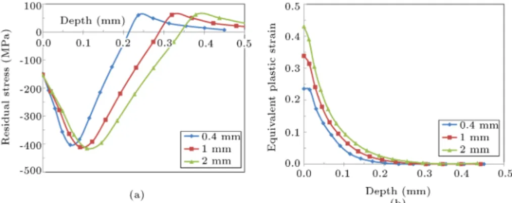
The eect of shot size on the residual stress prole as well as equivalent plastic strain at constant velocity of 50 m/s is illustrated in Figure 11. It can be observed that despite increasing the shot diameter, inducing plastic deformation in larger volume, the magnitude of maximum subsurface residual stress remained almost the same. But both the benecial depth at maximum residual stress and total depth at zero residual stress increased linearly with shot size. However, maximum equivalent plastic strain along with its depth increased with increase in shot size. As shown in Table 1, yield strength of the target material is 330 MPa, whereas its work (strain) hardening modulus is 480 MPa, vey lower than its elastic modulus of 71.7 GPa. These properties
Figure 11. Eect of shot diameter on (a) residual stress and (b) equivalent plastic strain.
represent the target behaviour like an elastic-fully-plastic material with little strain hardening.
When the induced stress due to the impact of shot reaches yield strength of the target material, the resid-ual stress changes negligibly, but the material ows substantially with little hardening. Here, the residual stress is controlled by yield strength of the material and the plastic deformation by larger straining with little hardening. Therefore, by increasing the shot velocity and size, the maximum subsurface residual stress is negligibly changed, whereas the plastic deformation is increased due to larger straining and no hardening. Similar trends of residual stress and plastic deformation for various shot sizes have been reported in [1,27]. Figure 11 can be used to specify size of shots for the required level of residual stress and plastic strain in aluminium plates.
4. Conclusions
Finite element models consisting of an elasto-plastic aluminium alloy as a target plate and elastic steel shots were developed in explicit dynamics solution code LS/Dyna to analyse shot peening process. The strain rate dependent constitutive behaviour of target plate was described by Johnson-Cook's plasticity model. The modelling procedure and simulation results were validated with published data. The obtained simu-lation results were in accordance with the published ones, and the numerical models demonstrated their capability to simulate the patterns of residual stress and plastic deformation observed experimentally in aluminium alloys. The numerical models enhanced understanding of the complex impact process and parametric study investigated the relationship among various factors involved. It was observed that the higher the shot velocity, the larger the depth of residual stress would be, resulting in larger plastic zone in target plate. Furthermore, increasing the shot size resulted in an increase in plastic deformation. Nevertheless, the maximum subsurface residual stress was negligibly
inuenced by the shot velocity and size. In industry, the study can be used to select a proper set of peening parameters for specic levels of residual stress and plastic deformation in aluminium alloy components, especially aero engine compressor blades. Such data seems to be very dicult to obtain with experimenta-tion.
References
1. Meguid, S.A., Shagal, G., Stranart, J.C., and Daly, J., \Three-dimensional dynamic nite element analysis of shot-peening induced residual stresses", Finite Elem. Anal. Des, 31(3), pp. 179-191 (1999).
2. Majzoobi, G., Azizi, R, and Nia, A.A. \A three-dimensional simulation of shot peening process using multiple shot impacts", J. of Mater. Proc. Tech., 164, pp. 1226-1234 (2005).
3. Hong, T., Ooi, J., and Shaw, B. \A numerical sim-ulation to relate the shot peening parameters to the induced residual stresses", Eng. Fail. Anal., 15(8), pp. 1097-1110 (2008).
4. Mann, P., Miao, H.Y. Gariepy, A., Levesque, M., and Chromik., R.R. \Residual stress near single shot peening impingements determined by nanoindentation and numerical simulations", J. of Mater. Sci., 50(5), pp. 2284-2297 (2015).
5. Shukla, P.P., Swanson, P.T., and Page, C.J. \Laser shock peening and mechanical shot peening processes applicable for the surface treatment of technical grade ceramics: A review", Proc Inst Mech Eng B J Eng Manuf., 228(5), pp. 639-652 (2014).
6. Tang. L, Yao, C., Zhang, D., and Ren, J. \Empirical modeling of compressive residual stress prole in shot peening TC17 alloy using characteristic parameters and sinusoidal decay function", Proc Inst. Mech. Eng. B. J. Eng. Manuf. (2016).
7. Marini, M., Fontanari, V., Bandini, M., and Benedetti, M. \Surface layer modications of micro-shot-peened Al-7075-T651: Experiments and stochastic numerical simulations", Surf. Coat. Technol, 321 (Supplement C), pp. 265-278 (2017).
8. Jebahi, M., Gakwaya, A., Levesque, J., Mechri, O., and Ba, K. \Robust methodology to simulate real shot peening process using discrete-continuum cou-pling method", Int. J. of Mech. Sci., 107, pp. 21-33 (2016).
9. Al-Obaid, Y.F. \Three-dimensional dynamic nite el-ement analysis for shot-peening mechanics", Comput. & Struct., 36(4), pp. 681-689 (1990).
10. Meguid, S.A., Shagal, G., and Stranart, J. \3D FE analysis of peening of strain-rate sensitive materials using multiple impingement model", Int. J. of Imp. Eng., 27(2), pp. 119-134 (2002).
11. Kang, X., Wang, T., and Platts, J. \Multiple impact modelling for shot peening and peen forming", Proc Inst Mech Eng B J Eng Manuf, 224(5), pp. 689-697 (2010).
12. ElTobgy, M.S., Ng, E., and Elbestawi, M.A. \Three-dimensional elastoplastic nite element model for residual stresses in the shot peening process", Proc Inst Mech Eng B J Eng Manuf, 218(11), pp. 1471-1481 (2004).
13. Bagherifard, S., Ghelichi, R., and Guagliano, M. \Mesh sensitivity assessment of shot peening nite element simulation aimed at surface grain renement", Surf. Coat. Technol, 243, pp. 58-64 (2014).
14. Bhuvaraghan, B., Maeo, S.S.B., McCLain, R., Pot-dar, Y., and Prakash, O. \Shot peening simulation using discrete and nite element methods", Adv. in Eng. Soft., 41(12), pp. 1266-1276 (2010).
15. Chen, Z., Yang, F., and Meguid, S. \Realistic nite element simulations of arc-height development in shot-peened almen strips", J. of Eng. Mater. and Tech., 136(4), p. 041002 (2014).
16. Hassani-Gangaraj, S.M., Cho, K.S., Voigt, H.-J.L., Guagliano, M., and Schuh, C.A. \Experimental as-sessment and simulation of surface nano crystallization by severe shot peening", Acta Mater., 97, pp. 105-115 (2015).
17. Jiabin, Z., Shihong, L., Tianrui, W., Zhen, Z., and Wei, Z. \An evaluation on SP surface property by means of combined FEM-DEM shot dynamics simulation", Adv. in Eng. Soft., 115 (Supplement C), pp. 283-296 (2018).
18. Xiao, X., Tong, X., Goa, G., Zhao, R., Liu, Y., and Li, Y., \Estimation of peening eects of random and regular peening patterns", J. of Mater. Proc. Tech., 254 (Supplement C), pp. 13-24 (2018).
19. Tu, F., Delbergue, D., Miao, H., Klotz, T., Brochu, M., Bocher, and P., and Levesque, M. \A sequential DEM-FEM coupling method for shot peening simulation", Surf. Coat. Technol, 319 (Supplement C), pp. 200-212 (2017).
20. MIL-HDBK-5J - Metallic Materials and Elements for Aerospace Vehicle Structures, D.o.D. Handbook, Edi-tor USA (2003).
21. Johnson, G.R. and Cook, W.H. \A constitutive model and data for metals subjected to large strains, high strain rates and high temperatures", in Proc. of the 7th Int. Sym. on Ballist., The Hague, The Netherlands, (1983).
22. Muhammad, R., Ahmed, Ullah, H., and Silberschmidt, V.V. \Dynamic behaviour of -Ti-15333 in ultrason-ically assisted turning: Experimental and numerical analysis", Scientia Iranica, Transac. B: Mech. Eng., 24(6), pp. 2904-2914 (2017).
23. Hfaiedh, N., Peyre, P., Song, H., Popa, I., Ji, V., and Vignal, V. \Finite element analysis of laser shock peening of 2050-T8 aluminum alloy", Int. J. of Fatig., 70, pp. 480-489 (2015).
24. ANSYS LS-DYNA User's Guide Ver 16.0. (2016).
25. Shaw, K.D.L. \Comparison between shot peening and surface nano crystallization and hardening processes", Mater. Sci. and Eng. A., 463, pp. 46-53 (2007).
26. Mylonas, G.I. and Labeas, G. \Numerical modelling of shot peening process and corresponding products: Residual stress, surface roughness and cold work pre-diction", Surf. Coat. Technol., 205(19), pp. 4480-4494 (2011).
27. Guagliano, M. \Relating Almen intensity to residual stresses induced by shot peening: a numerical ap-proach", J. of Mater. Proc. Tech, 110(3), pp. 277-286 (2001).
Biographies
Himayat Ullah obtained his Bachelor's degree in Mechanical Engineering in 1998 from University of Engineering and Technology (UET), Peshawar, Pak-istan. Also, he obtained his Master's in Mechani-cal Engineering in 2004 from UET, Taxila, Pakistan and completed his PhD at Loughborough University, UK, in 2013 in the eld of damage and fracture of composite structures. He is currently working as a principal engineer at Centres of Excellence in Science & Applied Technologies (CESAT), Islamabad, Pakistan. His research interests include analysis of damage and fracture of composite structures under various loading conditions, ballistic impact and crash study of com-posites, high-speed impact surface treatment processes of metal, multi-scale modelling of textile composites, impact fatigue and strain-rate dependent behaviour of composites, and buckling and stability of thin walled metallic and composite structures.
Baseer Ullah is currently working as a principal engineer at CESAT, Islamabad, Pakistan. He received his BSc degree in Mechanical Engineering with three gold medals from UET, Peshawar, and his MS degree
with a gold medal from the Ghulam Ishaq Khan (GIK) Institute of Engineering and Technology, Topi, Pakistan, in 2002 and 2004, respectively. In 2014, he completed his PhD degree in Structural Optimisation at the University of Durham, UK. His research activi-ties include structural optimisation, boundary element method, level set method, and NURBS.
Abdul Rauf received his BSc and MSc degrees in Mathematics from the University of Peshawar, Pak-istan, in 1993 and 1996, respectively. He received his PhD degree in the area of mechanical vibration from the University of Nottingham, UK, in 2006. Currently, he is working as a chief engineer at CESAT, Islamabad, Pakistan. His research activities include nite element
analysis; vibration analysis; composite materials; and nonlinear structural static, dynamic, and coupled eld analysis.
Riaz Muhammad graduated in Mechanical Engineer-ing with distinction from UET Peshawar, Pakistan, in 2006 followed by his MSc and PhD degrees in Mechan-ical Engineering from the GIKI Institute of Science and Technology and Loughborough University in 2009 and 2013, respectively. He is currently working as an Associate Professor in the Department of Mechanical Engineering, CECOS University of IT and Emerging Sciences, Pakistan. His research activities include nite-element modelling, hybrid machining process, composite, polymers, and biomedical materials.