*Correspondence to Author:
K. Vijaya Kumar
Department of Physics, JNTUH College of Engineering Sultanpur, Sultanpur(V), Pulkal (M), Sangared-dy-District, 502293, Telangana State, India.
How to cite this article:
K. Vijaya Kumar,R.Sridhar, D.Ravin-der. Dielectric properties of Chromi-um substituted Nickel nano ferrites . International Journal of Nanoparti-cle Research, 2018; 2:6.
eSciPub LLC, Houston, TX USA. Website: http://escipub.com/
K. Vijaya Kumar et al., IJNR, 2018; 2:6
International Journal of Nanoparticle Research
(IJNR)
Research Article IJNR (2018) 2:6
Dielectric properties of Chromium substituted Nickel nano ferrites
Background The powders of Ni-Cr Nano ferrites were
synthesized with the chemical formula, NiCrXFe2−XO4 (Where
X = 0.1, 0.3, 0.5, 0.7, 0.9 and 1.0) by using citrate-gel auto combustion technique. The structural characterization was investigated by X-Ray Diffractomerter (XRD). X-ray analysis shows that the samples are cubic spinel structure (single phase) without any impurity peak and average crystallite size was in the range of 8.5-10.5nm. The dielectric measurements were carried out as a function of frequency and composition (X) at room temperature in the range of 20Hz-2MHz. The real part of
dielectric constant (ε') and dielectric loss factor (tan δ) showed
a decreasing trend with increasing field frequency. The ac
conductivity (σac) is calculated from the dielectric measurements
and it is increased with the increase of frequency. The composition dependent dielectric parameters are reported.
Keywords: Ni-Cr nano-ferrites: Citrate-gel technique: XRD: Dielectric parameters:
K. Vijaya Kumar 1*,R.Sridhar2, D.Ravinder3
*1Department of Physics, JNTUH College of Engineering Sultanpur, Sultanpur(V), Pulkal (M),
Sangareddy-District, 502293, Telangana State, India.
2Department of BS&H, Vignan Institute of Technology & Science,Yadadri-Bhuvanagiri-Dist.508284, Telangana State, India.
3Department of Physics, Osmania University, Hyderabad-500007, Telangana State, India.
ABSTRACT
Introduction
Among the spinel ferrites, nickel ferrite a typical inverse spinel ferrite has been generally used in electronic devices such as telecommunication equipments, excellent core materials for power transformers and microwave devices for the reason that of their remarkably high electrical resistivity, mechanical hardness, chemical stability and low cost value [1]. Many investigators have been focused on substituted nickel ferrites as they have high frequency applications [2]. The properties of ferrites are also dependent on preparation method, chemical composition and type of substituent [3]. Divalent or trivalent substituted nickel ferrites are important materials, extensively used as magnetic materials in a wide range of technological applications because of their high electrical resistivity, low eddy current, low dielectric and magnetic losses [4-5].
For the synthesis of nanostructured materials offer some advantages by the chemical techniques in comparison with the physical techniques concerning simplicity, energy saving and product homogeneity. Several chemical methods were developed for preparing nano ferrites, the citrate-gel auto combustion technique has been used for the synthesis of nanosize spinel ferrites because of the low cost, simplicity, time period is very less and homogeneity of final product are included among its advantages. .
Fe3+ ion replace with trivalent cations like Cr3+,
Al3+ etc in divalent ion is involved to achieve
definite objectives [6]. Antiferromagnetic nature Cr3+ ions are known for achieving good control
over magnetic and dielectric parameters in build up particular significant materials. Many researchers had been reported the influence of trivalent substitutions to improve their structural and dielectric properties in nickel ferrite system [7-8]. Best of my knowledge, there are no such incorporated study has been reported in the literature on the preparation and dielectric properties of Cr3+ substituted nickel nano
ferrites through the citrate-gel auto combustion
technique. Therefore, the aim of the present investigation is to synthesis of the compositions NiCrXFe2-XO4 (Where X=0.1, 0.3, 0.5, 0.7, 0.9
and 1.0) by citrate-gel auto combustion method and dielectric properties as a function of frequency and composition at the room temperature of nickel nano ferrite have been investigated and hereby reported.
Experimental procedures
The mixed Ni-Cr nano ferrite system having the compositional formula NiCrXFe2-XO4 (Where
X=0.1, 0.3, 0.5, 0.7, 0.9 and 1.0) were synthesized by citrate-gel auto combustion method. Analytical grade raw materials (Nickel Nitrate (Ni(No3)26H2O), Chromium Nitrate
(Cr(NO3)23H2O), Ferric Nitrate (Fe(NO3)29H2O),
Citric Acid-Citrate (C6H8O7H2O) and Ammonia
(NH3)) were used as starting materials for the
synthesis. The required quantities of metal nitrates with aqueous solution of citric acid (1:3 molar ratio of nitrate to citric acid) were dissolved in deionized water. Ammonia solution was then added with a constant stirring to maintain the pH of the solution at 7. The resulting solution was continuously heated first on hot plate at 80oC to transform into gel and
then ignited in a self-propagating combustion manner to form a fluffy loose powder. The as-burnt ferrite powders were grained by agate motor to get ferrite powder. Then, the ferrite powder calcined in air at 700oC for 5hrs and the
calcined ferrite powders were again grained by agate motor to get a fine ferrite powder. As this technique is a chemical route, it requires no ball milling hence little scope of contamination, better homogeneity, low sintering temperature, less preparation time and it has the capacity to yield a homogeneous mixture of the constituent ions. The calcinations powder samples were thoroughly mixed with 3wt% PVA binder (poly vinyl alcohol) drying at 500C. The samples were
silver coated on both sides and air dried to have good ohmic contact.
The structural characterization was carried out using X-ray Diffractomerter (Bruker (Karlsruhe, Germany) D8 advanced system) with a monochromatic diffracted beam Cu Kα radiation
(λ=1.5405 Ǻ) source between the Bragg angles 20O to 80O in steps of 0.04O/Sec. The
crystallite size was calculated for all prepared samples using the high intensity 311 peak and Scherer Formula [9]
The dielectric constant values of the prepared samples were measured in the frequency range of 20Hz-2MHz at the room temperature using a
PRECISION LCR METER-E4980A. The
dielectric constant (ε') was calculated by using the relation [10].
The dielectric loss factor (tan δ) was measured by using the following relation [11]
The ac conductivity was determined using the following relation [11]
Results and Discussion:
XRD analysis
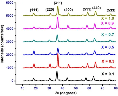
Figure 1 shows the X-ray diffraction pattern of mixed Ni-Cr nano ferrite system. It shows the crystalline phases were identified with standard reference data PDF# 862267 for Nickel ferrites (NiFe2O4) from the international centre for
diffraction data (ICDD). It was observed that XRD pattern imply spinel phase and all the samples show cubic spinel structure in single phase without showing any other impurity phases [12].
The average crystallite size was in the range 8.55 -10.36 nm and the values are reported in table 1. Best of my knowledge the small size mixed Ni-Cr nano ferrite samples are possible
only with the citrate-gel auto combustion method and the no other method has resulted the such a small size nano ferrites. By this method, phase of the prepared ferrite samples can produce very fast at low temperature but
conventional methods need to high
temperatures and prolonged heating time [13-14].
Dielectric properties
Frequency Dependence of the Dielectric Constants (ε')
Figure 2 shows the frequency dependence of the dielectric constant (ε') of mixed Ni-Cr nano ferrite system in the frequency range of 20Hz to 2MHz at the room temperature. It is clear that dielectric constant decreases with increasing frequency, it is a normal behavior of ferrites. In the low frequency region, the dielectric constant decreases sharply where as in the mid-range frequency region it decreases slowly and in the high frequency range, the dielectric constant is independent of frequency [15].
The variation of dielectric constant with frequency may be explained on the basis of space-charge polarization phenomenon [16]. According to this, dielectric material has well conducting grains separated by highly resistive grain boundaries. On the application of electric field, space charge accumulates at the grain boundaries and voltage drops mainly at grain boundaries [17]. Koop’s proposed that grain boundary effect is more at low frequencies [18], as the frequency is increased beyond a certain limit, the electron exchange between Fe2+Fe3+ ions does not follow the variations
in applied field. Thus, the value of dielectric constant becomes constant. Rabinkin and Novikova [19] pointed out that polarization in ferrites is similar to that of conduction.
Frequency Dependence of the Dielectric Loss Factor (tan δ)
Figure 1: XRD pattern of mixed NiCrXFe2-XO4 nano ferrite system
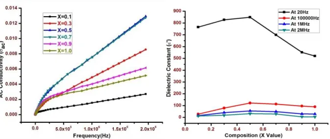
Figure 4 : Frequency dependence of Figure 5 : Dielectric constant (ε') variation ac conductivity with composition at various frequencies
Table -1: XRD pattern & Dielectric constant analysis of Ni-Cr nano ferrite system
Sl.No. Composition Crystallite size
(nm)
Dielectric constant (Ɛʹ)
AT
20Hz
AT
105Hz
AT
1MHz
AT
2MHz
1 NiCr0.1Fe1.9O4 8.96 765.32 27.45 15.04 11.85
2 NiCr0.3Fe1.7 O4 10.36 827.12 78.74 40.54 17.86
3 NiCr0.5Fe1.5.O4 7.95 848.84 121.89 54.57 31.24
4 NiCr0.7Fe1.3O4 8.55 699.14 112.62 48.88 28.65
5 NiCr0.9Fe1.1O4 8.84 551.56 96.08 29.18 4.643
loss factor (tan δ) of mixed Ni-Cr nano ferrite system as a function of frequency (20Hz to 2MHz) at the room temperature. In the present system, the value of tanδ increases initially in all compositions and exhibits the loss factor which becomes maximum between 1X10³Hz
and 4X10⁴ Hz and further it has been
decreased by increasing the frequency. It shows the Debye-type relaxation and this type of peaking behavior is observed when the jumping frequency between Fe2+Fe3+ ions is
exactly equal to the frequency of the applied field [17]. Similar type of maxima in dielectric loss factor (tan δ) with the frequency has been reported by other researchers [20-21].
It is clear that dielectric loss decreases sharp at low frequency region and the rate of decrease is slow at high frequency region, it shows an almost frequency independent behavior. All the compositions are exhibited in dispersion due to the Maxwell-Wagner [22-23] interfacial type polarization in good agreement with Koop’s phenomenological theory [24].
According to Koop’s theory, the effect of grain boundaries is more at low frequencies which corresponds to a high resistivity. This fact indicates that more energy is required for electron exchange between Fe2+ and Fe3+ ions,
as a result the loss is high at low frequency region. It corresponds to a low resistivity due to the presence of grains in the high frequency region and hence a small energy is required for electron transfer between Fe2+ and Fe3+ ions at
the octahedral site resulting in a low loss. It is clear that the energy loss is decreased when Cr concentration is increased at high frequencies. The low loss at higher frequencies shows the potential applications of these materials in high frequency microwave devices. The dielectric loss tangent also depends on number of factors such as stoichiometry, Fe2+ content and
structural homogeneity which in turn it depends upon the composition and sintering temperature of the samples [25].
Frequency Dependence of the AC
Conductivity (σac)
Figure 4 shows the variation of the ac
conductivity (σac) of mixed Ni- Cr nano ferrite system as a function of frequency in the range of 20 Hz to 2 MHz at the room temperature. It is clear that ac conductivity increases at low frequency region and it is almost independent behavior at higher frequency region for all the compositions. This behavior is similar to Maxwell-Wagner type which is in good agreement with Koop’s phenomenological theory [23-24].
According to Koop’s phenomenological theory, the conductivity was found low at lower frequency region due to the hopping electrons between Fe2+ and Fe3+ ions is less as the grain
boundaries are more active which acts as barrier for mobility of charge carriers. The conductive grains become more active and promote the hopping electrons between Fe2+
and Fe3+ ions at higher frequency region, hence
the conductivity is more and they are taken apart for creating charge carriers, these charge carriers are responsible for increasing the ac conductivity. It is in good agreement with Zn-Cr ferrite system by R. M. Sebastian et al [26].
Compositional Dependence of Dielectric Constant (ε')
The variation of dielectric constant (ε') as a function of Cr3+ concentration in Nickel nano
ferrite system at the selected frequencies (20Hz, 10000Hz, 1MHz and 2MHz) are tabulated in table 1 as the evident shown in figure 5. It is clear that dielectric constant (ε') increase with the composition (X), reaches maximum at X=0.5 and thereafter they decrease with the further Cr concentration. This behavior can be explained by the dielectric polarization mechanism and it is similar to that of the conduction in ferrites, initial Cr ions prefer to occupy the octahedral site until the Cr concentration becomes greater than 50%, thereafter Cr ions may increase in tetrahedral sites causing migration of equal number of ions to the octahedral sites [27].
ferrites with local displacement of electrons in the applied field direction due to the electron exchange interaction between Fe2+Fe3+ ions.
In Ni-Cr nano ferrite system, Cr ions occupy octahedral (B) site and Fe ions are distributed equally into both tetrahedral (A) and octahedral (B) sites. For the initial addition of Cr concentration in the place of Fe ion, some of the Fe3+ ions are converted to Fe2+ ions to
maintain the charge neutrality. Therefore, electronic exchange interaction between Fe3+Fe2+ ions increases, hence the
resistance of grains decreases. This increases the probability of electrons to reach the grain boundary, as a result, polarization and dielectric parameters are increased [28]. For the further addition of Cr ion concentration, Fe3+ ions
decrease and there will the least possibility of electronic exchange interaction between Fe3+Fe2+ ions, hence it is decreased in
dielectric parameters with increasing in Cr concentration in the present system. Similar trend is reported in Mg-Cr ferrite system by Raghasudha et al [29].
It can be seen from the table that the composition with X= 0.5 exhibits high dielectric constant 848.84 at 20Hz among mixed Ni-Cr ferrite system under investigation, due to the fact that it has maximum number of ferrous ions whose exchange Fe2+Fe3+ gives rise to
maximum dielectric polarization.
Conclusions
The Citrate-gel auto combustion technique is to be a convenient and versatile method for obtaining homogeneous nanostructured mixed Ni-Cr ferrites. The XRD pattern shows the
single phase cubic spinel structure with the average crystallite size in the range of 8.55 nm to 10.36 nm. The dielectric constant decreases with increase in frequency which is a normal behavior of ferrites due to hopping electrons between Fe2+ and Fe3+ ions at localized sites.
Dielectric loss factor (tan δ) increases initially in all compositions and exhibits the loss factor which becomes maximum between 1X10³Hz
and 4X10⁴ Hz further it has been decreased by
increasing the frequency. It shows the Debye-type relaxation and this Debye-type of peaking behavior is observed when the jumping frequency between Fe2+Fe3+ ions is exactly
equal to the frequency of the applied field. The ac conductivity increases with increasing in frequency at low frequency region and it is almost independent behavior at higher frequency region with the frequency. This behavior is similar to Maxwell-Wagner type in good agreement with Koop’s phenomenological theory. The dielectric constant (ε') becomes maximum at X=0.5 thereafter decreases with increasing in Cr ion concentration.
Acknowledgments
The authors are grateful to Head, Department of Physics, Osmania University, Hyderabad for provided the facility to synthesis of samples.
One of the authors (KVK) is grateful to Dr. K. Eshwara Prasad, Principal JNTUH
College of Engineering, Sultanpur, Pulkal (M), Madak and the author (RS) is grateful to Dr. G. Durga Sukumar Principal, Vignan Institute of Technology & Science, Yadadri-Bhuvanagiri (Nalgonda).
References
[1] Smit, J., Wijn, H.P.J.: Ferrites. Philips Technical Library, The Netherlands (1959)
[2] D. Ravinder, S. Srinivasa Rao, P. Shalini, Mater. Lett. 57 (2003) 4040.
[3] M.M. Hessien, M.M. Rashad, K. El-Barawy, J.Magn. Magn. Mater. 320 (2008) 336.
[4] Visuanathan, B., Murthy, V.R.K.: Ferrites Materials Science and Technology. Narosa Publishing House, New Delhi, India (1990).
[5] T. Abraham, Am. Ceram. Soc. Bull. 73 (1994) 62. [6] R.C. Kambale.N.R. Adhate, B.K. Chougule, Y.d. Kolekar, Journal of Alloys and Compounds 507 (2010) 372-377.
[7] M.K. Fayek, S.S. Ata Allah, Phys. Stat. Sol. (a) 198 (2003) 457.
[9] B. D. Cullity, “Elements of X-Ray Diffraction,” Addition Wesley, Boston (1959) 132.
[10] S. L. Gupta and S. Gupta, “Electricity, Magnetism and Electronics,” Vol. 1, Jaiprakash Nath and Company, (1991), 60.
[11] E. Pervaiz and I. H. Gul, J.Magn. Magn. Mater.Vol. 324 No. 22 (2012) 3695-3703.
[12] Devan, R.S., Kolekar, Y.D., Chougule, B.K. J. Phys., Condens. Matter, 18 (2006) 9809–9821
[13] R. G. Gupta and R. G. Mendiratta, Journal of Applied Physics, Vol. 48 No. 2 (1977) 845-848.
[14] R. G. Gupta and R. G. Mendiratta, Journal of Applied Physics, Vol. 48, No. 7 (1977) 2998-3000. [15] B. Chandra Babu, V. Naresh, B. Jayaprakash, S. Buddhudu, Ferro Electrics letter, 38 (2011) 114-127. [16] S. Sindhu, M.R. Antharaman, B.P. Thampi, K.A. Malini and Ph. Kurian, Bull. Mater. Sci. 24 (2001) 623-629.
[17] N. Rezlescu, E. Rezlescu, Physica Status Solidi (a), 23 (1974) 575-582.
[18] I.H. Gul, A. Maqsood, M. Naeem, M. Naeem Ashiq, J. Alloys comp.507 (2010) 201-206.
[19] I.T. Rabinkin, Z.I. Novikova, Ferrites, IZV Acad. Nauk USSR Minsk (1960) 146-147.
[20] C. B. Kolekar, P.N. Kamble, S.G. Kulkarni, A.S. Vainkankar, Journal of Mater. Sci. 30 (1995) 5784. [21] R.K.Kotnala, M.Abdullah Dar, Vivek Verma, A.P.Singh, W.A.Siddiqui Journal of Magn. Magn. Matter, 322 (2010) 3714-3719.
[22] J. C. Maxwell, “Electricity and Magnetism,” Vol. 1, Oxford University Press, Oxford, (1929).
[23] K. W. Wagner, American Physics, American Physics, 40 (1913) 817.
[24] C. G. Koops, Physics Revision, Vol. 83 No. 1 (1951) 121 - 124.
[25] R.S. Devan, B.K. Chougule, J. App. Phys. 101 (2007), 01419-1 to 014109-6.
[26] R. M. Sebastian, K. Maniammal, Sh. Xavier, Nano Studies, 8 (2013) 121-130.
[27] D. Elkony, Journal of Solids, Vol. 27 No. 2 (2004) 285.
[28] A.K. Singh, T.C. Goel, R.G. Mendiratta, J. Appl. Phys. 91 (2002) 6626.