Document category | Product name
Pipe Frost Protection
Application manual
Index
1. Application briefing 4
2. System Description 5
3. Products 7
4. System design 11
5. Installation 20
6. Cases 28
Let Danfoss do the work
Danfoss Group is Denmark's largest industrial group. It is one of the world's leading companies within heating, cooling and air-conditioning. The Danfoss Group has more than 23000 employees and serves customers in more than 100 countries.
Danfoss is Europe’s leading brand of electrical cable heating systems and electric pipe heating systems with over 70 years of experience. The production of heating cables takes place in France and Poland while the head office is situated in Denmark.
Cold stores, Ice stadiums and alike
This design guide presents Danfoss’s recommendations for design and installation of frost protection for pipes. It provides guidance for heating cable layout, electrical data and system configurations.
Following Danfoss’s recommendations will ensure energy efficient, reliable and maintenance free solution for constant wattage heating cables with 20 year warranty, self-limiting heating cables with 5 years of warranty.
Our quality management
system
and compliances
Along with full compliance with EU directives and product approvals
ISO 9001 TS 16949 ISO 14001
1. Application
briefing
During the winter, problems with freezing in fresh water, waste water, cooling water, supply water and sprinkler systems can be avoided by internal or external pipe heating. Pipes installed outdoor or inside unheated premises, even if insulated, can be subjected to low temperatures that results in ice generation inside pipes.
When water turns to ice its volume expands and in closed pipes ice becomes strong enough to cause pipe bursting. This results in damages, water leakage and costly repairs.
Danfoss heating systems provide an affordable, easy to install and adjustable solution in the form of a thermostat regulated heating cable. This solution provides a pipeline owner with a safe, maintenance free and sustainable system ensuring proper performance for years.
DEVI’s pipe tracing systems can be used for inside and outside applications in individual pipes and pipelines as well as for overhead and buried pipelines.
Benefits
• Avoiding unforeseen repair costs:
Frost
protection of pipes eliminates expensive repairs
and replacements after a long cold winter.
• Secures
constant flow of water
in pipes, even in
the coldest and unpredictable conditions.
• Any installation areas:
Can be used on and in
pipes, indoor, outdoor and in ground.
• Approved for use in drinking water supply
systems.
• Reduced cost of installation
in rocky and other
ground types, by alowing shallower installation.
• Possibility for
retrofitting of insulated pipes.
insulaiotn aluminum tape heating cable sand soil / ground
electrical connection box thermostat
EFET 610
sewer drain
fire fighting installation
Cold water installation
-10°C
-20°C
thermostat EFET 330 in electrical connection box
temperature
sensor heating cable
water pipe
thermostat EFET 330
electrical connection box
2. System Description
Danfoss heating system provides a versatile solution for water pipes protection (including drinking water pipelines) against freezing.
For on-pipe application: ECflex constant wattage cables or self-limiting cables (SLC) such as DEVIpipeguard™.
For in-pipe application:
DEVIaqua™ constant wattage cables or self-limiting cables (SLC) such as DEVIpipeheat™ provide flexible and on-site cut-to-length solutions.
The system is regulated by means of EFET 330 or 610 electronic thermostats. This is needed for constant wattage cables and strongly advised for self-limiting cables (SLC) to prevent energy consumption during standby periods.
To ensure energy efficient solution the use of an aluminum tape for cable installation, thermal insulation of pipes and electronic thermostats for control are essential.
Electronic thermostats DEVIreg™ have a sensor placed directly on pipe to be protected under its insulation, and ensure optimal operation with minimal energy consumption.
Pipe tracing Sensor Heating cable Insulation Fitting Valve
Aluminum tape
In-pipe frost protection Insulation
Heating Cable
Subsurface pipe tracing
Concrete breeze block (not always installed)
and/or XPS insulation (not always installed)
Danfoss heating cable Sand bed
Soil
Heating cables can be used with either metal or plastic pipes (e.g. PVC, PE, PP etc.). Plastic pipes may have limitations with regard to the output of a heating cable installed.
For more information please refer to the design section of this Application Manual as well as confirm temperature limits for plastic pipes with your supplier.
Installations are divided in two general application categories:
• Inside buildings • Outside buildings
The outside application category can be additionally divided into:
• in air
• in ground installation, as shown on the pictures above.
Installation inside buildings Water supply pipes installed inside buildings, where temperature may fall below 0 °C, e.g. unheated parking areas.
For such applications installation of electrical heating cables to ensure sustainable water flow and to prevent icing and subsequent pipe bursting is strongly advisable and in many cases required by law.
For further detailes investigate local buidling norms.
Outside above ground installation Pipes installed outside buildings are especially in need of frost protection. The primary protection is ensured by insulation but often to protect pipes in extreme weather conditions or in course of economic feasibility it's advantageous to install an electrical heating system (cables and thermostat).
Examples of such installations can be found: on roofs of shopping arcades, office buildings, hotels or utility buildings like water stations.
Outside in-ground installation Water pipes insulated and protected with electrical heating systems can be installed in ground at a shallower depth. In some areas, where the ground is composed of solid rock, this is the most economically feasible solution.
Location of electrical heating cables has to be clearly marked following local electricity laws. Marking shall include at least a yellow or red warning label indicating a supply voltage level. Additionally, if the cable is not protected by a concrete block, or similar, a thick plastic tape should be placed on top and slightly above the cable for its entire length. This is to minimize the possibility of mechanical damage during possible excavation activities in the future.
3. Products
Heating cables
The following heating cables can be used for protection of water pipe heating systems:
Heating cables for on-pipe installation: • Resistive (constant wattage):
ECflex 6T, ECflex 10T, ECflex 18T; ECbasic 10S, ECbasic 20S. • Self-limiting cables (SLC;
variable wattage): SLPG-10,
SLPG-25, SLPG-33; SLIG-18.
Heating cables for in-pipe installation: • EFTWC-9 and
self-limiting Danfoss pipeheat SLPH-10, (both for in- and on-pipe installation).
Both these cable types, mentioned as "in-pipe installation" are approved for use in contact with drinking water. The heating cable is relatively stiff, which makes the installation easier. The polyethylene coating prevents any output or taste alteration of drinking water.
Self-limiting heating cables are equipped with a temperature sensitive resistant element between two parallel copper conductors. When conductors are connected to the mains, the current flows through the temperature sensitive element which starts heating. As the element is heated, the resistance value rises causing the current decrease and then the heating is reduced. This explains the self-limiting output effect.
Such independent output regulation takes place on the entire cable based on the actual ambient temperature. When the ambient temperature rises, the cable heating output is reduced. This self-limiting capability allows avoiding cable overheating even in case if two cables cross or touch each other.
Autonomous power supply of self-limiting heating cables allows their shortening or extending in any place. This simplifies cable planning and installation.
In order to limit power consumption the heating cable should switch on/ off if it’s length exceeds approx. 3 m, e.g. by using a DEVIreg™ thermostat.
Self-limiting cables
SLPH-10
SLPG-10
SLPG-25
SLPG-33
SLIG-18
Resistive cables
EFSIC
ECflex
Thermostats
To control a pipe heating system EFET 330 (5…45 °C) thermostat with DIN rail attachment and pipe or wall mounted EFET 610 (IP44) are recommended.
All thermostats are equipped with wire temperature sensors in set – NTC 15 kOhm @ 25 °C, 3 m.
Fixing & Connection
Attaching cable to metal or plastic pipes is recommended by means of adhesive aluminum tape.
A large choice of connection sets, shrink tube or system-sets is available for connection and interconnection of heating cables (including SLC) to power supply and to each other. See also the next page.
A larger variety of connecting accessories (fixed as well as based on shrinking-tube) for self-limiting heating cables is available.
For more information please refer to the Danfoss product program or contact your local Danfoss provider.
EFET 330 EFET 610
Glued aluminum tape with warning signs (#19805076)
Connection box (#19400167) SLC to box connection set (#19400100)
Connecto B-C Connecto B-TE2 Connecto B-X
Article no. Illustration Name Description
088L0416 Connecto B-S Heating cable connection with 1,5 m
power cable and end terminal
088L0414 Connecto B-C Heating cable slice/extension for con-necting two heating cables
088L0417 Connecto B-T Heating cable T-branch as a T-junction for three heating cables and 1 end terminal
088L0418 Connecto B-TE2 Heating cable double connection with 1,5
m power cable and 2 end terminals
088L0419 Connecto B-TE3 Heating cable T-branch with 1,5 m power
cable and 3 end terminals
088L0420 Connecto B-X Heating cable X-branch for 4 heating cables incl. 2 end terminals
088L0413 Connecto B-A Heating cable connection with power
cable 1,5 m without end terminal
088L0415 Connecto B-E Heating cable end terminal
Danfoss Connecto system
installation steps
1. Cut the heating cable straight 2. Push the heating cable in 3. Twist untill closed
Product overview for the Pipe Frost Protection
Product Options Description
ECflex
Resistive heating cable
ECflex 6T, 230 V; ECflex 10T, 230 V; ECflex 18T, 230 V
Twin conductor, 100% screen. 6, 10 or 18 W/m (230 V); Ø 6,9 mm. DIN IEC 60800:2009 M2
EFSIC
Resistive heating cable
EFSIC 10, 230 V, on drum; EFSIC 20, 230 V, on drum; EFSIC 20, 400 V, on drum
Single conductor, wire screen.
10 W/m (230 V), 20 W/m (230 V/400 V); Ø 5,5 mm. DIN IEC 60800:1992 M2
ECaqua
Resistive heating cable EFTWC-9 with 3/4+1" Pipe fitting
Twin conductor, wire screen, 9 W/m (230 V); Ø 5,7 mm
Approved for use in drinking water. Danfoss iceguard
Self-limiting heating cable SLIG-18, with plug, 2-50 m;SLIG-18, on drum 18 W/m @ 0 °C.11,8 x 5,8 mm.
Danfoss pipeguard Self-limiting heating cable
SLPG-10, on drum SLPG-25, on drum SLPG-33, on drum
10 W/m @ 10C 25 W/m @ 10C 33 W/m @ 10C 11,8 x 5,8 mm Danfoss pipeheat
Self-limiting heating cable inside pipe
SLPH-10 with plug, 2-25 m. Accessory:
3/4"+1" Pipe fitting (13 bar @ 22 °C)
10 W/m @ 10 °C, 100% screen. 7,7 mm × 5,3 mm.
Approved for use in drinking water.
Danfoss thermostat EFET 330 (5…45 °C) 5…45 °C, 16 A, IP20,DIN rail
Danfoss thermostat EFET 610 -10…+50 °C, 10 A, IP44, wall/pipe installation
Temperature sensor 10 m, PVC Wire sensor, Ø 8 mm, IP65, NTC 15 kOhm @ 25 °C
Temperature sensor 40 m (Santropene) Wire sensor, Ø 5 mm, IP67, NTC 15 kOhm @ 25 °C
Assembly kit DEVIcrimp™ CS2A/CS2B and other assembly kits For 2-conductor cable
Fixing Aluminum tape Glued aluminum tape 38 mm x 50 m;0,06 mm; max. 75 °C
For details please refer to the Danfoss Catalogue. Various specific assembly kits are available.
4. System design
Output of heating cables installed on pipe should not be less than the calculated pipe surface heat loss multiplied by 1,3 safety factor. In most cases 10 W/m output is enough if: • the pipe diameter does not exceed
50 mm,
• the insulation thickness is at least the same as the pipe diameter,
• the temperature of surroundings does not fall below -30 °C.
• the required temperature inside the pipe is 5 °C.
In other words, for the above
conditions, the only one 10 W/m cable line (ECflex 10T, etc.) is required. Note. For plastic pipes the linear
output of resistive heating cables should not exceed 10 W/m. This restriction does not apply to self-limiting cables (SLC).
Following pages will help step-by-step to make a right design choice.
Inside pipe
dimension mm" 15½ 20¾ 251 1¼32 1½40 502 2½65 803 1004 1506 2008 25010 30012 35014 40016 45018 Insulation
thickness ΔT°C
10 mm 20 30 40 60 80 100 120 7,2 10,7 14,3 21,5 28,6 36,0 44,5 8,4 12,6 16,8 25,2 33,7 42,4 52,3 10,0 15,0 20,0 30,0 40,0 50,3 62,2 12,0 18,0 24,0 36,0 48,1 60,5 74,8 13,4 20,2 26,8 40,2 53,6 67,4 83,4 16,2 24,4 32,5 48,7 65,0 81,7 101,0 19,0 29,0 38,0 58,0 77,0 97,0 119,0 23 34 45 68 90 114 140 29 43 57 86 114 144 177 41 61 81 122 163 205 253 52 78 104 156 208 261 322 64 95 127 191 255 320 395 74 111 148 222 295 372 459 81 121 162 243 323 407 502 92 138 184 276 368 463 572 103 155 207 310 413 520 641 20 mm 20 30 40 60 80 100 120 4,6 6,8 9,1 13,6 18,2 23,0 28,4 5,3 7,9 10,6 15,7 21,0 26,4 32,8 6,1 9,1 12,2 18,2 24,4 30,7 37,9 7,2 10,8 14,4 21,6 28,8 36,2 44,9 7,9 11,9 15,8 23,9 31,8 40,0 49,4 9,4 14,2 18,8 28,2 37,7 47,4 58,7 11,0 16,0 22,0 33,0 44,0 55,0 68,0 13 19 25 38 51 64 79 16 24 32 48 63 80 99 22 33 44 67 89 112 138 29 42 56 84 113 142 175 34 51 68 103 137 172 212 40 60 80 120 160 202 249 44 66 88 131 175 220 272 50 75 99 149 199 250 309 56 83 111 167 222 280 346 30 mm 20 30 40 60 80 100 120 3,6 5,4 7,3 10,9 14,5 18,2 22,7 4,1 6,1 8,3 12,4 16,4 20,8 25,7 4,7 7,1 9,5 14,2 18,8 23,8 29,4 5,5 8,2 10,9 16,4 21,8 27,6 34,1 6,0 9,0 12,0 18,0 24,0 30,1 37,3 7,0 10,6 14,0 21,0 28,0 35,3 43,6 8,0 12,0 16,0 24,0 32,0 41,0 50,0 9 14 19 28 37 47 58 11 17 23 34 46 57 71 16 24 31 47 63 79 98 20 30 40 59 79 100 123 24 36 48 72 96 121 149 28 42 56 84 112 141 174 31 46 61 91 122 153 190 34 52 69 103 138 174 215 38 58 77 116 154 194 240 40 mm 20 30 40 60 80 100 120 3,1 4,7 6,2 9,4 12,5 15,7 19,6 3,5 5,3 7,1 10,6 14,0 17,6 22,0 4,0 6,0 7,9 12,0 20,0 24,8 4,6 6,8 9,1 13,7 18,2 23,0 28,4 4,9 7,4 10,0 14,9 19,9 25,1 31,0 5,8 8,6 11,5 17,3 23,0 28,9 35,9 7,0 10,0 13,0 20,0 26,0 33,0 41,0 8 11 15 22 30 38 47 9 14 18 27 37 46 57 12 19 25 37 50 63 72 16 23 31 46 62 78 96 19 28 37 56 75 94 116 22 33 43 65 87 109 135 24 35 47 71 94 119 147 27 40 53 80 107 134 166 29 44 59 89 119 150 185 50 mm 20 30 40 60 80 100 120 2,8 4,2 5,6 8,4 11,3 14,2 17,5 3,1 4,7 6,2 9,4 12,5 15,7 19,6 3,5 5,3 7,1 10,6 14,0 17,8 22,0 4,0 6,0 8,0 12,0 16,1 20,2 25,0 4,3 6,5 8,6 13,8 17,4 21,8 27,0 5,0 7,4 10,0 15,0 19,9 25,1 31,1 6,0 9,0 11,0 17,0 23,0 28,0 35,0 7 10 13 19 26 32 40+ 8 12 16 23 31 39 48 10 16 21 31 42 52 65 13 19 26 39 51 65 80 16 23 31 46 62 78 96 18 27 36 54 72 90 112 19 29 39 58 78 98 121 22 33 44 66 88 110 136 24 37 49 73 97 123 152 75 mm 20 30 40 60 80 100 120 2,4 3,5 4,7 7,1 9,4 11,9 14,6 2,6 3,8 5,2 7,8 10,3 13,1 16,1 2,9 4,3 5,8 8,6 11,5 14,5 17,9 3,2 4,8 6,5 9,7 12,9 16,2 20,0 3,5 5,2 7,0 10,4 13,8 17,4 21,6 3,9 5,9 7,8 11,8 15,6 19,7 24,4 5,9 6,0 9,0 13,0 18,0 22,0 27,0 6 7 10 15 20 25 31 7 9 12 17 23 29 36 8 11 15 23 30 38 48 9 14 19 28 37 47 58 11 17 22 33 44 56 68 13 19 26 38 51 64 80 14 21 28 41 55 69 86 15 23 31 46 62 78 96 17 26 34 51 68 88 107
Table with required minimal outputs in [W/m], for straight pipelines (without flanges, valves or T-branches). Frost protection of pipe systems [W/m]
The table below shows the heat loss for 1 meter of pipe for various pipe dimensions, insulation thicknesses and temperatures.
To define the heat loss follow the pipe diameter (in [mm] or [inch]) at the top bar of the table towards the row with the insulation thickness and using the appropriate temperature
difference you will find the heat loss value at the crossing point.
λ – insulation material value (e.g. mineral wool) for this table is 0,04 W/mK.
Values in table can be caluclated with help of formula on next page.
4.1. Step-by-step system design
Following pages provide an easy step-by-step design guide for selection of a Danfoss pipe frost protection system. The recommendations are provided relate both constant wattage cables and self-limiting cables, as well as thermostats and accessories. The detailed example is provided at the end of this chapter.
X lnX
1,0 0,0
1,5 0,4
2,0 0,7
2,5 0,9
3,0 1,1
3,5 1,3
4,0 1,4
4,5 1,5
5,0 1,6
6,0 1,8
7,0 1,9
8,0 2,1
9,0 2,2
10,0 2,3
15,0 2,7
20,0 3,0
25,0 3,2
d
D
t
ut
oHeat loss calculation
Step 1
2 3 4
5
Heat loss calculation
Step 1
2 3 4
5
Product selection
Step
1
2
3 4 5
Cable length selection
Step
1 2
3
4 5
Regulator selection
Step
1 2 3
4
5
Accessories selection
Step
1 2 3 4
5
The most important factors to define the pipe heat losses are the following: • Pipe diameter
• Insulation thickness
• Difference between inside (desired maintained temperature) and outside pipe temperatures (e.g. outdoor) temperature of the installation site).
The following formula is used for heat losses calculation for total length of a pipe to be protected:
Where:
D [m] - Outside pipe diameter incl. insulation d [m] - Pipe diameter without insulation l [m] - Total length of pipe
tu [°C] - Desired maintained temperature to [°C] - Outside temperature
λ [W/m°C] - Thermal conductivity of insulation 1,3 - Safety factor
λ value for standard insulation material (like glass wool or styropor), is set to 0,04 W/mK.
Heat loss values from the table on the previous page calculated by the above formula and divided by total Q [W] = 2 · π · λ · l · (tu - to) · 1,3
ln(D/d)
pipe length. The obtained values are in [W/m].
Natural logarithm (ln) values for D/d ratio is in the table above, where X = D/d.
Constant wattage heating cables Are typically used in case of simple straight pipe lines installed in a similar thermal environment.
In such cases selection of the heating cable directly depends on the pipe length.
In case of installation of new pipes, or longer pipe lines, the use of on-pipe heating cables is preferable.
For shorter or existing pipes installation of in-pipe heating cables is the only feasible or available choice.
There are three different cables for selection with different linear output (10 W/m or 18 W/m). It's necessary to choose a heating cable with output equal or higher than the one calculated by the formula (including 1,3 safety factor).
Cable outputs are calculated for 230 V. For 220 V the displayed output value in [W] shall be multiplied by 0,91 factor. E.g. ECflex 10T, 60 mm with output of 600 W at 230 V, has the output of only 546 W at 220 V.
Example (see also Step 1) • Pipe diameter D = Ø 65 mm • Insulation thickness = 20 mm • Thermal conductivity value for
insulation λ = 0,04
• Desired temperature tu = +10 °C • Minimum outside temperature
to = -20 °C
Heat loss Q is calculated with help of formula from Step 1 or from table on page 11.
Q = 16 W/m
Product selection
Step
1
2
3 4
5
ECflex 18T Output
(W)
Length (m)
130 7,3
180 10
270 15
395 22
535 29
615 34
680 37
820 44
935 52
1075 59
1220 68
1340 74
1485 82
1625 90 1880 105 2135 118 2420 131 2775 155 ECflex 10T
Output (W)
Length (m)
100 10
205 20
290 30 390 40 505 50
600 60
695 70
795 80
920 90
990 100
1220 120 1410 140
Self-limiting heating cables (SLC) SLCs are often used for pipe systems with many branches, because it's easier to adjust the cable length to appropriate pipe length (SLC can be cut to length provided that the maximum cable length is observed). The self-limiting function, that allows SLC output adjustment based on the pipe temperature, is a rather useful feature. However the self-limiting cable regulation by a thermostat is recommended due to continuous use of the SLC, even if heating is not needed.
When choosing a self-limiting heating cable it's essential to investigate whether the heating cable can provide the required output at the desired temperature.
How to read the graph Draw a line from the desired temperature value (X-axis) and a calculated heat loss output (Y-axis). Afterwards find a heating cable with output values higher (Y-axis) than the cross point of temperature and output lines.
Example (see also Step 1) • Pipe diameter D = Ø 65 mm • Insulation thickness = 20 mm • Thermal conductivity value for
insulation λ = 0,04
• Desired temperature tu = +10 °C • Minimum outside temperature
to = -20 °C
Heat loss Q is calculated by the formula of Step 1 or from the table on page 11. Q = 16 W/m
Product selection
Step
1
2
3 4
5
The choice is for SLIG-18 with linear output of 18 W/m at 10 °C
0
0
10
20
30
40
50
60
10
15
5
20
25
35
30
40
DEVIpipeheat™ 10 DEVIpipeguard™ 10 DEVIpipeguard™ 25 DEVIpipeguard™ 33 DEVIiceguard™ 18 DEVIhotwatt™ 55
Linear output [
W/m]
Pipe temperature [°C]
Desired temperature tu= +10 °C
Calculated heat loss Qj= 16 W/m
ECflex 18T Output
(W)
Length (m)
130 7,3
180 10
270 15
395 22
535 29
615 34
680 37
820 44
935 52
1075 59
1220 68
1340 74
1485 82
1625 90 1880 105 2135 118 2420 131 2775 155
Cable length selection
Step
1 2
3
4
5
Constant wattage heating cables All ECflex constant wattage heating cables are manufactured with specific lengths. A product to be chosen should be of the same length or longer than the entire length of the pipe to be protected.
If the protected pipe is fitted with some components such as flanges, valves, supports, T-branches, or sprinklers some extra cable length shall be applied. In this case use the calculation formula in chapter 4.1. Important:
It's strictly forbidden to cut a constant wattage cable. In case of surplus cable length it should be wound around the pipe, or for metal pipes only it should be drawn along the pipe at its end.
Length of cable is connected to the power supply and it's used to its full availability. A total length of the cable has to be used. Reducing cable length by its cutting is strictly forbidden. Spiral winding of heating cable around a pipe gives better heat division and protection, but requires more space around the pipe during installation and thus can be unfeasible in some cases. For further advice concerning the cable layout please refer to chapter 5.1 (Installation).
Example: Pipe length L = 50 m, Q = 16 W/m (as before)
ECflex 10T Output
(W)
Length (m)
100 10 205 20 290 30 390 40 505 50 600 60 695 70 795 80 920 90 990 100 1220 120 1410 140
Heating cable of L = 52 m and 935 W output is chosen.
Steel pipe Connection point
Lcable = 52 m
Lcable = 52 m
Steel and plastic pipes Connection point
Self-limiting heating cables Self-limiting heating cables are available on drums and ready to be cut to length. The maximum length of SLC is defined by: a cable type, start-up temperature and a fuse size.
The length of a self-limiting heating cable should be enlarged in case of presence of valves, flanges and alike, in the same way as for constant wattage cables (see chapter 4.1 for further details).
Maximum length of connected self-limiting heating cables
The maximum length of the combined (all parts) self-limiting heating cables can't exceed the value for this cable included in the table below. Total cable length
Ltotal = part 1 + part 2 + part 3 ≤ ≤ max. allowed length (Lmax cable) Example: At start up temperature of +10 °C, 10 A fuse and SLPG-18, Lmax cable = 58 m
T-branch points part 1
part 2
part 3 Connection point
230V
Cable length selection
Step
1 2
3
4
5
Example: Pipe length L = 50 m SLIG-18 – 50 m Q = 16 W/m
The choice is for SLIG-18 with 50 m length.
Ltotal < Lmax
Maximum length values for SLCs at different start-up temperatures and fuse sizes
St
ar
t-up
te
m
p
er
atu
re Max. length of heating cable at 230 V [m]
Danfoss pipeguard 10 Danfoss pipeguard 18 Danfoss pipeguard 25 Danfoss pipeguard 33 Fuse size of C characteristic
10A 16A 25A 32A 10A 16A 20A 25A 10A 16A 25A 32A 10A 16A 25A 32A
–20°C 97 156 226 226 35 56 70 87 46 74 116 146 28 45 71 91
–10°C 110 176 226 226 39 63 79 99 52 84 131 146 32 51 81 103
0°C 119 191 226 226 43 70 88 110 58 93 146 146 36 58 91 117
+10°C 119 191 226 226 58 93 116 145 58 93 146 146 42 67 105 120
Maximum cable lengths are defined for the case when the cable is switched on being unheated.
In this case its power consumption will be in the range of 1,8 - 2,3 times of its nominal value, when reaching its operating temperature.
Start-up temperature is the ambient temperature at which the SLC is turned on. Very often this temperature equals the desired maintained temperature values.
Temperature regulation Constant wattage as well as self-limiting heating cables require a thermostat for regulation. The thermostat ensures maintaining constant temperature and turning the heating on while limiting energy consumption, even for SLCs that are constantly on and even if it’s not required.
The thermostat selection depends on the specific installation. The most common systems are described on this page, either with a sensor placed directly onto the pipe (under the insulation) or based on the air temperature sensor.
Systems with a sensor installed directly on the pipe to be protected is of the most use.
Temperature regulation using air sensor
This system is based on the air sensor that is installed close to the protected pipe and that turns on the heating when the ambient temperature falls below the set value.
Regulator selection
Step
1 2 3
4
5
thermostat air temperature sensor
thermostat
thermostat on-pipe mounted sensor
on-pipe mounted sensor
thermostat on-pipe mounted sensor Frost-protection installation.
Pipe of different diameters. Installation completed with self-limiting heating cable.
Frost-protection installation. Pipe of different diameters. Installation completed with constant wattage heating cable.
If the size of the heating elements exceeds the maximum limit defined by the thermostat, the connection to more heating elements needs to be ensured by means of relays / switches. In such installations, one thermostat can regulate several heating elements. Such set up is primarily used in cooperation with self-limiting heating cables.
Advantage of this system is mostly visualized in regulating of pipe frost-protection systems, where pipes have different sizes and insulation thickness.
Temperature regulation using on-pipe sensors
This type of installation, where the sensor is placed directly on pipe under insulation, is more precise and energy efficient way of regulation than the air sensor.
On-pipe sensor regulation is often used for systems with many pipes and branches, with different temperature settings or conditions.
It requires, as shown on the picture, more thermostats, and is necessary when:
• pipes have different sizes or insulation thicknesses;
• changing temperature conditions, e.g. pipe from building to outside, and back to the building, or installed above or underground;
• mixed pipes delivering stagnant and moving water;
• pipes delivering any fluid sensitive to rapid temperature changes This type of regulation, with on-pipe sensor, is required when installation is performed with constant wattage cables, or on plastic pipes (e.g. PVC, PP, PE, PE-X).
Accessories selection
Step
1 2 3 4
5
1st layer of tape
heating cable (between layers of aluminum tape)
heating cable (between layers of aluminum tape) heating cable
(under the tape)
aluminum tape
plastic pipe metal
pipe
2nd layer of tape
1 m 1 m
app. 1,5 m tape on 1 m of pipe (pipe dimension Ø 150 mm)
app. 2,5 m tape on 1 m of pipe (pipe dimension Ø 150 mm)
1st layer of tape
heating cable (between layers of aluminum tape)
heating cable (between layers of aluminum tape) heating cable
(under the tape)
aluminum tape
plastic pipe metal
pipe
2nd layer of tape
1 m 1 m
app. 1,5 m tape on 1 m of pipe (pipe dimension Ø 150 mm)
app. 2,5 m tape on 1 m of pipe (pipe dimension Ø 150 mm)
1 m 1 m
connection box
installation through the insulation pipe insulation
power connection
end muff (part of a heating cable) ECflex constant
wattage cable connection muff
(part of a heating cable)
Constant wattage and SLC cables In case of metal pipes the heating cable can be attached to the pipe by means of an aluminum tape placed at intervals of approx. 1 meter. Subsequently, the total length of the heating cable needs to be covered with aluminum tape, securing cables to the pipe.
In case of the plastic pipes, before mounting the cable onto the pipe, the aluminum tape needs to be applied on the pipe where the heating cable will be placed. Other part of the installation steps resembles that of the installation on metal pipe.
Selection of connection boxes and accessories for constant wattage cables
Constant wattage cables are fitted with connection boxes, so no additional connection accessories are needed. If electric conneciotn point requires, a connection box can be used.
thermostat
sensor placing
underground P-lot drive in
nawiew zimnego powietrza thermostat
sensor placing
underground P-lot
Choice of the thermostat also relates to its temperature range, expected place of installation (in DIN-rail box or outside) and any additional requirements.
Sensor placing
Sensors for pipe frost-protection systems should be installed in a place that is the most representative for the installation, i.e.in the expected coldest point of this installation (e.g. on pipe part facing the entrance to the unheated parking area).
Example:
Pipe length 50 m, a frost protection installation with a Danfoss iceguard 18 self-limiting cable with DIN-rail attachment.
Maintained temperature = +10 °C.
Solution is EFET 330 (-10...+10 °C), but EFET 330 (+5...+45 °C) can also be considered.
For more information please refer to chapter 3 (Products) or to the Danfoss Product Catalogue.
Regulator selection
Accessories selection
Step
1 2 3 4
5
Selection of connection accessories for self-limiting heating cables
Connection sets for connection to box and SLC to SLC contain also end elements.
Connection to power supply can be done with a heating cable connected via connection box (option no. 1), or end up with cold tail connected with help of option no. 2.
bracket
SLC to SLC connection set power cable
to power supply 230V
to power supply 230V
connection to box connection to box
through insulation set
Set of accessories for connection to power supply (option no. 1):
1 x Connection box 1 x Connection to box 1 x Bracket
1 x Through Insulation set
Complete set for 1 branch:
1 x Connection box 3 x Connection to box 1 x Bracket
3 x Through Insulation set
Set of accessories for connection to power supply (option no. 2):
1 x SLC to SLC connection set 1 x Through Insulation set
end element from connection to box
end element from connection to box
Beside shrink tube connection sets, Danfoss provides a wide range of easy-fix connection sets for self-limiting heating cables.
For more details please see chapter 3 (Products) and the Danfoss Product Catalogue.
5. Installation
5.1. General information
Pipe conditions
Before installing heating cables it is important to check the pipe for any signs of damage or leakage.
The pipes should be insulated as this reduces the heat losses considerably. This applies for all pipes whether they are below or above the ground. The cable should be attached to the pipe gently, so it does not get damaged. The entire length of the cable should be attached to the pipe with aluminum tape and NOT plastic tape (e.g. PVC), as it contains plasticizers.
The cable should be laid in such a manner to avoid sharp edges on the pipe. Treading on cables should be avoided and cables should be treated carefully at all times.
All pipe trenches should be distinctly marked to indicate that heating cables have been installed on/ in them. It should also be marked with a distinct warning sign, e.g. “WARNING: 230 VOLT HEATING CABLES“.
Insulated pipes must be marked with a warning sign placed on the outside of the insulation material.
Heating cable should not be pulled with more than 25 kg.
Electrical conditions
The screen of the heating cables must be earthed in accordance with the local electricity laws.
The resistance and the insulating resistance of the heating cable must be checked before and after installation. The resistance value must be as indicated on the label of the connection box.
The sensor cable can be extended to any reasonable length using a cable of min 2 x 0,75 mm².
The cable is attached to the pipe with strips of aluminum tape placed at intervals of approx. 1 meter. When the heating cable has been attached to the pipe, the entire length of the heating cable must be covered with lanes of aluminum tape. This prevents the heating cable from getting into direct contact with the insulation material and ensures a tight fit between the pipe surface and the heating cable. Before the heating cable is attached to the plastic pipe, a full lane of aluminum tape should be applied to the pipe for the cable to lie on. This ensures a better heat distribution to the pipe. Cables should be attached at the lower part of the pipe or/and symmetrically around the pipe.
The connection muff between the heating cable and the cold tail should also be fixed with aluminum tape. The sensor cable is attached to the pipe in the same way as the heating cable. The tip at the end of the sensor should be covered with aluminum tape and be positioned centrally between the cable lines and on top of the pipe, if possible.
The heating cable must not be led through valves. The heating cable is relatively stiff that makes the installation easier.
The cable must be evenly spread and the crossing of resistive cables must be strictly avoided.
Pipes are usually insulated with plastic foam, mineral wool or another kind of insulation, which can range in thickness, typically not less than the pipe diameter.
The insulation should be protected against damp and moisture that could damage the insulation and reduce its efficiency.
Ensure that insulation with bigger inner diameter is chosen, taking into account that the pipe diameter is increased due to heating cable installation.
Below ground installation If cables are installed above the ground in trays, it should be safe and solid. It should be marked with a distinct warning sign, e.g. “WARNING: 230 VOLT HEATING CABLES“.
When heating cables are installed below the ground, a plastic tape (red, yellow etc.) is laid on top of the pipes/ installation to indicate that cables are placed just below.
For this type of installation it is necessary to measure the required pipe run precisely, as the cable cannot be cut or bent in a loop.
You will need an appropriate DEVIcrimp™ assembly kit to perform cold tail connections and end muff of heating cables on drums. For instance, DEVIcrimp™ assembly/ repair kit 2-cond. CS2A/CS2B (product number: 18055350).
Installation examples
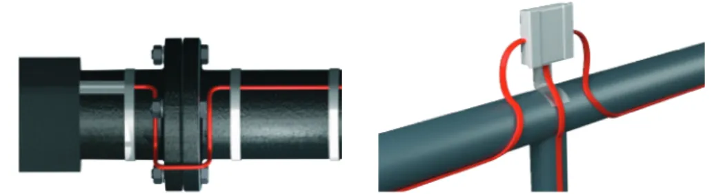
Installation on Special Flanges and PumpsAlways observe the minimum tolerable bending diameter of 25 mm (32 mm for Danfoss iceguard 18)! Heating cables on specials, valves etc. should always be positioned so that they are easily accessible and replaceable in connection with inspection and repair and so that it will not be necessary to cut them! You can avoid this problem when there is sufficient cable wrapped in a spiral around the specials.
Mounting example around a valve and a support flange. Example of cable mounting on a flange.
Valve Aluminum tape
Support bracket Heating cables
Example of mouting a self-limiting cable on pipe with use of connection box and metal bracket.
Outer pipe diameter
[mm]
Inner pipe diameter
[mm]
Inner pipe diameter
[inch]
C-C distance [mm]
Cable length in [m] for each pipe meter
1,1 1,2 1,3 1,4 1,5
34 25 1 250 170 140 110 100
42 32 1 ¼ 310 210 170 140 130
48 40 1 ½ 350 240 190 160 140
60 50 2 430 300 240 200 180
76 65 2 ½ 520 360 290 240 210
89 80 3 630 430 350 290 260
102 90 3 ½ 720 490 390 330 290
114 100 4 800 560 440 370 330
141 125 5 990 680 550 460 400
168 150 6 1180 810 650 550 480
219 200 8 1520 1050 840 710 620
Table presenting a Cable-to-cable fixing distances when more than 1 meter cable is used on a 1 meter pipe. CC = π . d .
√
n21 - 1Lcable [m] = n · Lpipe + 0,5 · (C + FV + 2 · T)
Explanations for formulas: n Number of cable lines. (min. 2 for DN125-200)
Integer = straight lines (easier installation) Decimal = twisted around pipe
CC mm Centre distance for twisted cable n = decimal
Lcable m Total length of heating cable
Observe max. length for SLC (see product sheets) C Number of cable connections (0,5 m cable each) FV Number of flanges/valves (0,5 m cable each) T Number of T-branches (1 m cable each)
Quick solution finder
If you don't need to make a heat loss calculation, the following tables will help you quickly to find a correct product for frost protection of pipes. How to use the table below? Based on known pipe diameter e.g. Ø60 mm, with 20 mm insulation and Δt of 30K.
1. Find pipe size in mm or inches, in the top bar of the table.
2. Find the temperature difference (Δt), in the outmost left column. 3. Find the insulation thickness in the
corresponding raw (20 mm). 4. Follow the vertical and horizontal
lines, until they meet.
According to the table, when looking up into table on the previous page, a minimum output to be installed to protect the pipe from freezing is: 15-25 W/m.
Remember to choose preferably the higher output option, hence 20-25 W/m.
Specific pipe heat loss qpipe
ΔT Insulation Nominal pipe size NPS [inch], DN [mm]
[K] [mm] ½”
15 ¾” 20 1” 25 1¼” 32 1½” 40 2” 50 2½” 65 3” 80 4” 100 5” 125 6” 150 8” 200 20 10 20 30 40 50 30 10 20 30 40 50 40 10 20 30 40 50
Table presenting the necessary minimal outputs in [W/m] for straight pipelines (without flanges, valves or T-branches).
1
2
3
Number of cable lines Cable Output qcable [W/m]
0 - 6 6 - 10 10 - 15 15 - 25 25 - 50 >50
ECflex constant wattage ECflex 6T EFTWC-9 (in-pipe) ECflex 10T ECflex 18T 1 1 1 1 2 1 1 1 2 1 2-3 2 Max. 4
Max. 3 More insulation required
Self Limiting Cable
Danfoss pipeheat 10 (in-pipe) Danfoss pipeguard 10 Danfoss pipeguard 15 Danfoss pipeguard 25
1 1 1 1 2 1 1 2 1 2
Find an appropriate type and number of heating cables to protect the pipe in the following table.
qpipe= 1,3 . 2π . λ . Δt
= 1,3 . 2π . 0,04 . 30 = 19,2 W
In Dd In 10060 m
Example
A 12 meter DN50 (Ø 60 mm) drain pipe with 20 mm insulation and a drain valve needs frost protection down to -25°C (Δt = 30 K).
The specific pipe heat loss qpipe depends on the pipe diameter, insulation thickness and temperature difference. The specific pipe heat loss qpipe from the calculation table on page 22 = 15-25 W/m (yellow).
λ is a thermal conductivity for insulation ≈ 0,04 W/mK.
Exact pipe heat loss: Solution:
1 line Danfoss pipeguard 25 W/m with 1 cable connection is chosen.
Cable length:
Lcable = n · Lpipe + 0,5 · (C + FV + 2 · T) = =1 · 12 + 0,5 · (1 · 0,5 + 1 + 2 · 0) = 13 m As EFET 610 controller with a sensor cable is chosen to be attached between pipe and insulation.
Optionally: 2 parallel lines of ECflex 10T 15 m, with a total length of 30 m can be chosen.
5.2 Installation specifics
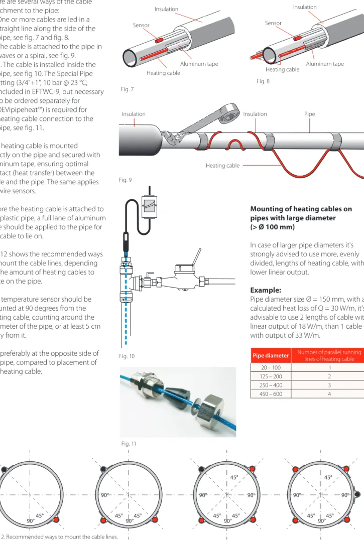
There are several ways of the cable attachment to the pipe:
1. One or more cables are led in a straight line along the side of the pipe, see fig. 7 and fig. 8.
2. The cable is attached to the pipe in waves or a spiral, see fig. 9.
3. 3. The cable is installed inside the pipe, see fig 10. The Special Pipe fitting (3/4"+1", 10 bar @ 23 °C; included in EFTWC-9, but necessary to be ordered separately for DEVIpipeheat™) is required for heating cable connection to the pipe, see fig. 11.
The heating cable is mounted directly on the pipe and secured with aluminum tape, ensuring optimal contact (heat transfer) between the cable and the pipe. The same applies for wire sensors.
Before the heating cable is attached to the plastic pipe, a full lane of aluminum tape should be applied to the pipe for the cable to lie on.
Fig. 12 shows the recommended ways to mount the cable lines, depending on the amount of heating cables to place on the pipe.
The temperature sensor should be mounted at 90 degrees from the heating cable, counting around the perimeter of the pipe, or at least 5 cm away from it.
But preferably at the opposite side of the pipe, compared to placement of the heating cable.
Mounting of heating cables on pipes with large diameter (> Ø 100 mm)
In case of larger pipe diameters it's strongly advised to use more, evenly divided, lengths of heating cable, with lower linear output.
Example:
Pipe diameter size Ø = 150 mm, with a calculated heat loss of Q = 30 W/m, it's advisable to use 2 lengths of cable with linear output of 18 W/m, than 1 cable with output of 33 W/m.
Pipe diameter Number of parallel running lines of heating cable
20 – 100 1
125 – 200 2
250 – 400 3
450 – 600 4
Insulation Insulation Pipe
Fig. 9
Heating cable
Sensor
Insulation
Fig. 8
Aluminum tape Heating cable
Sensor
Insulation
Fig. 7
Aluminum tape Heating cable
Fig. 10
Fig. 11
230 V power supply (circuit no. 1)
230 V power supply (circuit no. 2) part 1
circuit no. 1
part 1 part 3
part 3
par
t 1
par
t 4
par
t 2
circuit no. 2
230 V power supply (circuit no. 1)
heating cable no.1
pipe length 138 m
pipe length36
m
pipe length36
m
pipe length 28
m
230 V power supply (circuit no. 2)
230 V power supply (circuit no. 3)
230 V power supply (circuit no. 4) heating
cable no. 2 cable no. 3heating
heating cable no. 4
Division in circuits – self-limiting heating cables
Division in circuits – constant wattage heating cables
Example of a solution with use of self-limiting heating cables If the maximum length of self- limiting heating cable exceeds the length displayed on page 16 (under: choice of cable length), it needs to be divided into smaller portions.
Example:
With choice of SLPG-10, where the total length of the pipe is 256 m. Expected start-up temperature is -20 °C, desired pipe temperature is t = +5 °C, and a maximum available fuse size is: 16 A. From a table on page 16, the maximal cable length for this SLC is only: 156 m. It will be necessary to divide the pipe in 2 independent circuits, with separate power supply points, as shown on the picture. Example of division:
Circuit 1: part 1 + part 2 = 156 m Circuit 2: part 3 + part 4 = 100 m
Example of a solution with use of constant wattage heating cables In case of the constant wattage heating cables, the maximal length of the circuit is limited by the maximum allowed length of the heating cable. Because the constant heating cables are not allowed to be cut, at each T-branch, a new cable is connected. Each pipe needs to have a heating cable chosen to accommodate it's length.
Example:
For frost protection of a metal pipe shown on the picture, following solution was chosen.
• Heating cable no. 1: ECflex 10T, 140 m • Heating cable no. 2:
ECflex 10T, 40 m • Heating cable no. 3:
ECflex 10T, 40 m • Heating cable no. 4:
5.3 Installation Summary
20mm –25
o
C
DN25 +5oC
12
6
9 3
2. Draw a plan positioning cable(s), sensors and thermostat, cable con-nections, cold tail, connection box, cable paths and switch board. 1. Check the pipe system to be heated
and make sure that the pipes are dry, smooth and tight. Check and prepare the switch board.
5. Apply aluminum tape below (manda-tory for plastic pipes) and on top on the whole length of the cable. Make sure that the cables do not cross sharp edges without relief and that any constant wattage cables do not cross back on itself.
Attach the cable securely to the pipe with use of tape and taking care of preventing appearance of air pockets.
8. After insulation, place safety marking tape on the insulation jacket or pipe trenches for every 5 m. In subsurface installations, a cover ribbon with a warning sign must be laid 10 cm above the cables.
3. Check the insulation resistance and Ohm rating of the heating cables. Compare the Ohm rating with the nominal written on the cable label.
6. Attach and cover the sensor and the tip on top of the pipe with alumi-num tape. Extend cold tails / termi-nate cables and place conne- ctions dry. Mount connection box on the pipe or close to the pipe and install the thermostat next to the pipe. 4. Twisted lines are attached as shown
for every approx. 1 m pipe with aluminum tape.
Straight lines must be fitted as shown at 5 or 7 o’clock.
In-pipe cables are fitted directly into the pipe and tightened.
7. Re-check the insulation resistance and also Ohm rating for constant wattage cables. Connect cables to connection boxes and to the switch board.
Commissioning
9. Re-check and compare the insulation resistance and also Ohm rating for constant wattage cables and earth resistance.
10. Danfoss thermostat must be commissioned as prescribed in the thermostat manual. Recommended pipe temperature setting is +3 to +6 °C.
11. Train the end user or daily supervisor in the operation and maintenance of the frost protection system.
12. Before every heating season, check for faults in the switchboard, thermostat and sensors. Re-check and compare the insulation resistance and also Ohm rating for constant wattage cables and earth resistance.
5.4 Important
No alutape overheats constant wattage cables.
SLC will limit itself and heat insufficiently.
Alutape above and below the cable gives better performance.
50 mm insulation maintains Δt = 50K
20 mm insulation maintains Δt = 30K
Temperature distribution
Aluminum tape and insulation are im-portant when it comes to performance and very important in relation to plastic pipes. A DN50 plastic pipe (e.g. PP) with 10 W/m at reference tempera-ture -10°C is shown under 3 different installations.
Self-Limiting Cables and standby savings with thermostat
Always install a thermostat for self-limiting cables >3 m as it
• prolongs the cable lifetime; • saves the stand by energy
con-sumption;
• leaves e.g. drinking water cold and fresh, when no heat is needed.
SPAR ZENTRALE SALZBURG, Salzburg, Austria
Frost protection system on water pipes. Project size:
Danfoss pipeguard 10 - 700 m Centrally placed regulators- 25 pcs.
6. Cases
THE GAS TURBINE PLANT, Tereshkovo, Russia
Pipe tracing. Project size:
Danfoss pipeguard 33 - 170 m Danfoss pipeguard 25 - 635 m EFET 316 (10…+50 °С) - 17 pcs Outdoor sensor GB IP-44 - 17 pcs Connection kit for SL cables - 160 pcs DEVIfast™ (25m) - 36 pcs
![Table with required minimal outputs in [W/m], for straight pipelines (without flanges, valves or T-branches).](https://thumb-us.123doks.com/thumbv2/123dok_us/8479599.2262631/11.892.70.826.496.1166/table-required-minimal-outputs-straight-pipelines-flanges-branches.webp)
![Table presenting the necessary minimal outputs in [W/m] for straight pipelines (without flanges, valves or T-branches).](https://thumb-us.123doks.com/thumbv2/123dok_us/8479599.2262631/22.892.69.830.548.948/presenting-necessary-minimal-outputs-straight-pipelines-flanges-branches.webp)