LokProgrammer
v 4.0
Instruction manual
For software versions 4.4.13 and on
Article no.: Unofficial (See “About this manual” pg 42)
September 2014
Table of contents
Declaration of Conformity
3
WEEE-Declaration
3
1. Important notes – Please read this first
4
2. Installation and start-up of the LokProgrammer 4
2.1 System requirements
4
2.2. Connecting the LokProgrammer
4
2.3. Installing the software
4
2.4. Starting the program
4
2.5. Software updates
5
2.6. Firmware updates
5
3. LokSound basics
5
3.1. Sound characteristics of locomotives
5
3.2. User defined sounds
6
3.3. Automatic / Random sounds
7
3.4. Digital system / Protocols
7
3.5. CVs
7
3.6. Further information about LokSound decoders
7
4. Purpose of the LokProgrammer software
8
4.1. Overview
8
4. 2. Assistant
8
5. Main screen
9
5.1. View Panes
9
5.2. Task bar
9
2
5.3. Tools
9
6. Driver’s cab
11
7. Decoder Information, Read / Write CVs
11
8. The “decoder settings” register
12
8.1. Decoder address
12
8.2. DCC / Analogue
12
8.3. Compatibility
12
8.4. DCC Settings
13
8.5 Driving characteristics
13
8.6. Function views
14
8.7. Identification
17
8.8. Manual CV Input
17
8.9. Motor Settings
17
8.10. Smoke Unit
19
8.11. Sound settings
19
8.12. Sound slot settings
20
8.13. Special options
21
9. Information
22
9.1. Functions
22
9.2 General
22
10. Sound modeling, adding sounds
23
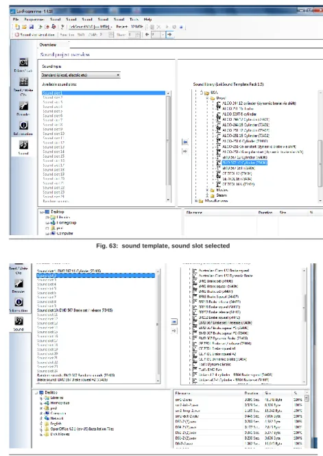
10.1. Sound section overview (opening view page)
23
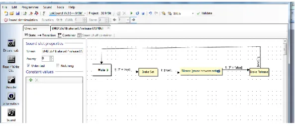
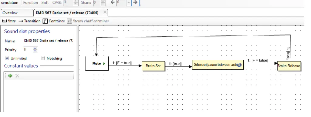
11. Sound modeling, flow charts
29
11.1. Sound flow chart basics
29
11.3. Containers and container properties
31
11.4. Complex sound flow
32
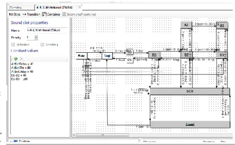
11.5. Steam sound flow chart
35
11.6. Sound modeling terminology
37
12. Sound modeling, Examples and Tips
38
12.1. Flowchart drawing example
38
12.2. 74482 GE P42 AMD 103 project examples
39
13. Errors and troubleshooting
41
13.1. Last transition must be unconditioned
41
13.2. Dangling outgoing transition
41
13.3...exit Dangling incoming transition
41
13.4. Unhandled exception
41
13.5. Problems when reading the decoder
42
13.6.Troubleshooting problems
42
13.7. Customer service – Assistance and support
42
About this manual:
42
Declaration of Conformity
We, ESU electronic solutions ulm GmbH & Co KG, Industrie- straße 5, D-89081 Ulm, declare herewith in sole responsibility compliance of the product "LokProgrammer“ to which this declaration is related to, with the following standards: EN 71 1-3 : 1988 / 6 : 1994 – EN 50088 : 1996 – EN 55014, part 1 + part 2 : 1993
EN 61000-3-2 : 1995 – EN 60742 : 1995 – EN 61558-2-7 : 1998 The „LokProgrammer“ bears the CE-mark according to the guidelines as per
88 / 378 / EWG – 89 / 336 / EWG – 73 / 23 / EWG
WEEE-Declaration
Disposal of old electrical and electronic devices (applicable in the European Union and other European countries with sepa- rate collection system). This mark on the product, the packaging or the relevant documentation indicates, that this product may not be treated as ordinary household garbage. Instead this product has to be delivered to a suitable disposal point for
recycling of electrical or electronic equipment. By disposing of this product in the appropriate manner you help to avoid negative impact on the environment and health that could be caused by inappropriate disposal. Recycling of materials contributes to conserve our natural environment. For more information on recycling this product please contact your local administration, the rubbish disposal service or the shop where you have purchased this product. Batteries do not belong into household trash!
Please do not dispose of discharged batteries in your household trash: take them to a collection point at your local town hall or dealer. Thus you assure an environmentally friendly way of disposal.
Copyright 1998 - 2009 by ESU electronic solutions ulm GmbH & Co KG. Irrtum, Änderungen die dem technischen Fortschritt dienen, Liefermöglichkeiten und alle sonstigen Rechte vorbehalten. Elektrische und mechanische Maßangaben sowie Ab- bildungen ohne Gewähr. Jede Haftung für Schäden und Folgeschäden durch nicht bestimmungsgemäßen Gebrauch, Nichtbeachtung dieser Anleitung, eigenmächtige Umbauten u. ä. ist ausgeschlossen. Nicht geeignet für Kinder unter 14 Jahren. Bei unsachgemäßem Gebrauch besteht Verletzungsgefahr.
Märklin® ist ein eingetragenes Warenzeichen der Firma Gebr. Märklin® und Cie. GmbH, Göppingen. RailCom® ist ein eingetragenes Warenzeichen der Firma Lenz Elektronik GmbH, Giessen.Alle anderen Warenzeichen sind Eigentum ihrer jeweili- gen Rechteinhaber.
ESU electronic solutions ulm GmbH & Co. KG entwickelt entsprechend seiner Politik die Produkte ständig weiter. ESU behält sich deshalb das Recht vor, ohne vorherige Ankündigung an jedem der in der Dokumentation beschriebenen Produkte Änderun- gen und Verbesserungen vorzunehmen.
Vervielfältigungen und Reproduktionen dieser Dokumentation in jeglicher Form be- dürfen der vorherigen schriftlichen Genehmigung durch ESU.
4
Installation and start of the
LokProgrammer
1. Important notes – Please read this first
Thank you for purchasing the LokProgrammer set 53450/ 53451. With the LokProgrammer you can program ESU LokPilot- and LokSound decoders.
The LokProgrammer 53450 consists of two elements: An interface module that serves as the physical connection between the PC and the locomotive, and the software that can be run on any PC using MS Windows. The set 53451 has an additional USB adapter but is otherwise the same as 53450. Never was it easier to program a digital decoder than with LokProgrammer. Thanks to the graphic interface of MS Windows you can achieve the optimal adaptation of LokSound decoders even if you have very little or no experience in programming digital decoders. This combination allows you to easily manipulate and adjust the many features and properties of LokSound decoders with your PC.
LokProgrammer also allows you to modify all sound fragments and sound effects stored on the decoder as often as you desire. ESU provides over 100 different sound files on the ESU web site at www.esu.eu. You will certainly find the right sound for your locomotive.
Please also take note of the license agreement regarding downloading and using the sound files contained in the appendix. This manual describes in detail how to modify sounds and which methods to use to achieve the desired results.
We wish you lots of fun in the world of LokSound.
ESU electronic solutions ulm GmbH & Co KG, November 2013
2. Installation and start-up of the
LokProgrammer
Please note the remarks regarding installation to assure that your LokProgrammer software keeps working to your full satisfaction!
2.1 System requirements
In order to use this software you need a commercially available PC with the following requirements:
• Operating system: Microsoft Windows 98, 2000 or XP, Vista,
Win7 32/64bit, Win8 and 8.1
•CD-ROM drive
• One serial port or an USB interface on your PC • Audio card
• 20MB minimum available memory on your hard disc For the utilization of the sound files with this software an Audio Card must be installed. All cards with a Windows driver are suitable.
2.2. Connecting the LokProgrammer
The LokProgrammer has to be connected as shown in Figure 1: Use the serial cable respectively the USB-adapter cable provided to connect the LokProgrammer to any available COM port (or USB-port) of your PC. Which port you select is immaterial. Please make sure that the programming track is completely isolated from the rest of the layout to avoid possible damage of your LokProgrammer hardware!
Also make sure that there are no electrical connections between the individual wires.
Fig.1.: Wiring the LokProgrammer
Fig.2.: Polarity of Power Supply Connector
There are two options for the power supply:
• Use the power pack with mains plug provided with the LokProgrammer. Connect the output of the power pack to the power supply terminals of the LokProgrammer as per Figure 2.
• Use the AC power output of a model train transformer and wire it to the screw terminals. We recommend this option for programming gauge 1 locomotives
Never connect both terminals at the same time. This could destroy the LokProgrammer!
After connecting the power supply the green LED on the LokProgrammer should light up.
The terminals „Track Out“ on the LokProgrammer are to be wired to the programming track. Polarity is irrelevant. Make sure that the programming track is fully isolated from the layout!
The two LEDs on the LokProgrammer indicate the following: Green LED:
• Is lit continuously when supply voltage is available.
• Blinks when the LokProgrammer receives data from the PC. Yellow LED:
• Blinks quickly when voltage is applied to the programming track and data is transferred.
• Blinks slowly if the LokProgrammer detects a high current and is disconnecting the programming track.
2.3. Installing the software
Make sure that the LokProgrammer is connected as described above and is ready for use.
As soon as you insert the CD-ROM into the drive the installation program is starting automatically.
Should this not be the case select the CD-ROM drive in „Desk Top“ or in the „Windows Explorer“ and click onto „Set up“. Alternatively you may click on the START button in the tool bar and select „Run“. Then type „x:\setup.exe“ and „OK“. Of course you must enter the name of the CD-ROM drive instead of the „x“ (usually „D“):
After a short while the program should start. Follow the instructions on the monitor and wait until the program is installed on the hard disk.
2.4. Starting the program
The installation program creates an entry in the start menu. Select „LokProgrammer vX“ in the Start menu under „Pro- grams“; „X“ stands for the version number of the software. Select „LokProgrammer“. Then the program will start.
LokSound Basics
2.5. Software updates
ESU offers the latest version of the LokProgrammer software on the web page www.esu.eu. You will find it in the „Down- loads“ menu under „Software“. Click onto the Download- symbol at the end of the line. A window opens. Click „Run“. Now the program will guide you through the installation procedure.
Fig.3.: Start Window for Internet Update
There is also an option for an automatic update provided the software is already installed on your computer:
• Go into the Start Menu and select Program „LokProgrammer vX“, (the X stands for the version number of your software). • Click onto „Internet Update“. A window as per Fig. 3 opens. • Click onto „Next“. The note „Downloading required Files. Please
be patient“ appears. While this window is shown the files required for the update will be installed. Subsequently you can start the LokProgrammer software from the installation window.
Please note that software version 4.4.7+ runs and opens appropriate data (meant for decoder versions 3.5 and v4.0) thus this software incorporates software 2.6.6 and on for v3.5 decoders and versions 4.4.1 and on for v4.0 decoders. You cannot mix and match features of decoder versions, software and firmware is distinctly different for each decoder version, but this software will open sound projects for both decoder architectures. Specifics for version 3.5 decoders are available in the programmer manual for that decoder. This manual is specific to v4 decoders.
2.6. Firmware updates
The firmware is the operating system of the LokPilot- or LokSound decoders.
Please note: Certain new software options can only be activated with LokSound decoders with the latest firmware-update. Firmware installs as required when sound data is written to the decoder.
Privacy Protection:
ESU guarantees that no information will be downloaded from your PC to the ESU website. Data transmission is strictly limited to sending data from the ESU home page to your PC. Your personal data are protected at any time.
3. LokSound basics
In the following chapter it is explained how the LokSound decoder reproduces prototypical sounds, what options are available with digital command control for model trains and which protocols of digital systems are currently available in the market. Should you already have experience with digital systems and also be familiar with locomotive sounds you may skip this chapter and continue reading on page 16.
3.1. Sound characteristics of locomotives
With LokProgrammer and LokSound decoders you can reproduce sounds of steam locomotives, diesel-hydraulic and diesel-electric locomotives, electric locos or locos with manual transmission (e.g.: rail car). Of course the sound sequences are subject to the type of locomotive.
3.1.1. Steam locomotive
The dominant sounds of a steam locomotive are the hissing of the boiler and the exhaust chuffs when the locomotive is running. The chuffs are synchronized to the revolutions of the drivers and therefore accelerate or slow down whenever the locomotive runs faster or slower. We differentiate between locomotives with 2 or 4 cylinders and others with 3 cylinders. A steam locomotive with 3 cylinders generates either 3 or 6 exhaust chuffs per revolution of the drivers while a 2- or 4- cylinder locomotive generates 4 exhaust chuffs per revolution. The exhaust chuffs appear to be louder and harder during acceleration compared to normal running at constant speed. Whenever the valves are closed the only audible noise is the clank of the driving rods.
When the locomotive starts moving, the cylinder valves are open in order to push out any condensed steam and thus to avoid breakage of the driving rods.
This behavior can be simulated with LokSound decoders and with the aid of the LokProgrammer. The individual stages are
divided into separate Driving notches. The different sounds of the respective stages consist of individual recordings of the exhaust chuffs (also refer to Fig. 4 and chapter 11.5 for detailed explanations).
Fig.4.: Performance of a Steam Locomotive
3.1.2. Diesel locomotive (diesel-electric)
Diesel-electric locomotives are in principle electric locomotives with electrical generators that are powered by diesel engines. The diesel locomotive is generally driven at constant Driving notches subject to the speed of the locomotive. Therefore the noise generated changes (driving) step by (driving) step. The quiet electric motor can hardly be heard over the noise of the diesel powered plant. Most diesel-electric locomotives have 4 to 8 throttle notches.
Examples of diesel-electric locomotives are the DB class 232 („Ludmilla“), most American diesel locomotives by GE or ALCO or the MZ-locomotives by the Danish State Railways.
Fig.5.: Performance of a diesel-electric locomotive
6
LokSound Basics
3.1.3. Diesel locomotive (diesel-hydraulic)
The main item of equipment of a diesel-hydraulic locomotive is the torque-converter that uses fluids for power transmission. This energy flow is literally „fluent.“
That is the reason why diesel-hydraulic locomotives howl audibly once the throttle is opened and before the locomotive is actually moving. Since the revs of the motor sound depend on the speed, the noises generated during driving change without audible thresholds. Simply put, the sound is directly proportio- nal to the speed.
Locomotives with LokSound decoders behave the same way; first the diesel engine revs up and once the revs are high enough the locomotive starts moving. The pitch of the sound can be adjusted subject to the speed. This is only possible in a combined unit (decoder plus sound module in one piece – for further info also refer to chapter 8.5.4). Examples for diesel-hydraulic locomotives are the DB class V200 (class 220) and the Regio-Shuttle or the DMU41 by the SNCB/NMBS.
Fig.6.: Performance of a Diesel-hydraulic Locomotive
3.1.4. Diesel locomotive with manual transmission (manual gear gear box)
Diesel locomotives with manual transmission employ pinion gear for transmitting the power from the motor to the wheels similar to automobiles. The clutch is pressed during shifting from one gear to the next and thus the power transmission is interrupted for a short moment. The shifting of gears can clearly be heard in many a diesel locomotive with manual transmission. With the LokProgrammer software you can either store the original sound of gear shifting or you may choose the option „gear shift“ (User-Sound Slot 14) as described in chapter 9.6.2:
Examples of diesel locomotives with manual transmission are the German rail cars VT95 or some shunting locomotives, since manual transmissions are only practical in vehicles of relatively low weight and with low maximum speeds.
Fig.7.: Performance of a Diesel Locomotive with Manual Transmission
3.1.5. Electric locomotive
There are different sound types for electric locomotives. On the one hand the hum of the electric traction motor(s) is audible; it changes its pitch with the speed similar to diesel-hydraulic locomotives.
Other electric locomotives generate very dominant fan sounds. In some electric locomotives the sound of the fan is constant and therefore the sound does not change during driving. By and large electric locomotives are not as noisy as other locomotive types and therefore they are ideal for applying User Sounds such as the whistle, horn, compressor, etc. (for more info please refer to chapter 9.5 and 9.6).
Fig.8.: Performance of an Electric Locomotive 3.2. User defined sounds
User-defined sounds („User-Sounds“) could be horns and whistles, coupler clank, sanding, etc. These sounds can be triggered by pressing a function button on your throttle once you have programmed them onto the decoder.
Currently LokSound decoders support up to 28 functions such as head lights, smo- ke generator, etc. The latest versions of digital command stations such as the ESU ECoS can fully utilize this range.
LokSound Basics
3.3. Automatic / Random sounds
Random Sounds are triggered automatically and irregularly and can be used for safety valves, fans, compressors, etc. With the LokProgrammer you can select the time between Random Sounds (details in chapter 8.5.3).
Other possibilities for triggering sounds automatically such as squealing brakes are contained in Decoder Settings and the appropriate flow chart (see chapter 9). Such sounds will be triggered at specific times based on those settings.
3.4. Digital system / Protocols
In this chapter we list all digital protocols for running model trains and setting signals and turnouts that are supported by the LokProgrammer.
3.4.1. DCC (NMRA)
DCC stands for „Digital Command Control“ and was formulated as standard by the NMRA (National Model Railroad Association). In the early stages operation was limited to 14 speed steps and 80 addresses; today up to 10,000 addresses and 128 speed steps are available.
DCC is downward compatible in terms of control and decoders, e.g. older decoders can be controlled with up-to-date command stations / throttles and with certain limitations new decoders can be operated and programmed with older control devices.
3.4.2. Motorola®
The Motorola®-protocol goes back to 1984 is one of the oldest digital systems for model trains. Due to its age the operational options are limited.
The Motorola®-protocol can only handle 80 locomotive addresses with 14 speed steps and besides the headlight function only four additional function outputs can be controlled (functions 5-8 can be selected with the second Motorola®-address). Since the Motorola®-protocol is still used in many digital systems ESU decoders are designed to work with this protocol as well.
3.4.3. M4
Since 2004 the MFX®-system is on the market. Theoretically this could run more than 16,000 model locomotives simultaneously with 128 speed steps.
The LokProgrammer software deals with certain settings somewhat differently to DCC.
For instance, instead of locomotive addresses the name of the locomotive has to be entered (e.g.: „class 01“ or „ICE“). The allocatement of certain parameters to the CVs is also different to DCC.
Do not use the DCC-CVs mentioned from chapter 3.5 onwards for M4!
What does M4 mean?
At some points in this manual you will notice the term „M4“ for the first time and rightly wonder what this might mean.
This question can be answered quite simply: from 2009 forward, M4 is the name of a data protocol that was chosen by ESU to be implemented in their decoders. Decoders with the M4 protocol are one hundred percent compatible with command stations using mfx®. At such stations (e.g. Märklin® Central Station®) they will be recognized automatically and all playing functions are available just like when using mfx®. On the other hand, our ESU command stations using M4 will recognize all (Märklin® and ESU) mfx® decoders without any restrictions and will still work without any problems. As the (mutual) inventor of mfx® we can assure you of this.
In short: the technique stays the same, only the name has been changed.
3.4.4. Selectrix®
Selectrix® is another digital system. In contradiction to DCC the locomotive addresses are not transmitted individually but in groups. Thus it is limited to the driving sounds and Random Sounds but it is not possible to trigger any user defined sounds (e.g.: a whistle or bell). Selectrix® is almost exclusively used for N scale and Z scale; therefore it is also supported by the ESU LokSound micro decoder.
It is important not to confuse these systems when programming any sounds. For instance is it not possible to store any M4- project files on a DCC-decoder let alone to replay them.
3.5. CVs
3.5.1 Definition and application
CV stands for „Configuration Variable“. CVs can have values in bits or bytes. The CVs with bytes can have a range from 0 to 255 while the CVs programmed in bits function as on / off- switches.
Examples:
CV 63 (sound volume) is a CV that can be programmed byte- wise with a maximum value of 192. The value 0 means no sound while 192 stands for maximum sound volume. (150%) In CV 49, bit 0 is a „switch“ for activating load compensation (as per 8.3.2). If this bit set to 0, load compensation is deactivated, is it set to 1, and then load compensation is active.
The NMRA (National Model Railroad Association) has allocated certain CVs to certain functions. For instance CV 1 is always used for the address, CV 5 for the maximum speed.
Advantages / Disadvantages
Digital decoders can be programmed without the need of comprehensive programming knowledge or equipment. Many digital command stations also offer internal programming menus.
Furthermore the programming with bits and bytes requires little memory space. Programming solely with CVs is not easy to remember and depending on the type of command station it can be quite cumbersome.
Furthermore CVs have only limited effect on sounds in LokSound decoders (e.g.: sound volume). The actual sounds cannot be adjusted with CVs but depend on the actual sound recording. In the LokProgrammer software CVs are shown in registers or as slide controls and can therefore easily be set to the desired values.
3.6. Further information about LokSound decoders
3.6.1. General
At the core of a LokSound decoder is a powerful processor. It is supported by an audio amplifier and a sound memory that can store up to 268.44 seconds of sound.
The eight channel mixer with active filter can replay eight diffe- rent sounds simultaneously: One channel is reserved for the driving sounds while the other seven can be used for other sounds (such as bells, whistles, etc.), Random Sounds (e.g.: automatic safety valves or shoveling coal), and brake sounds. All eight channels will be mixed to one output in the decoder and transmitted to the speaker.
The memory of the LokSound decoder can be deleted at any time to make room for new sounds. Thus it is no problem whatsoever to modify a steam sound decoder into diesel sound. You can easily do that yourself with the aid of the ESU LokProgrammer whenever you want to!
Please note: this unimpeded change of sounds is limited to decoders sold for installation into locomotives by the user. LokSound decoders that are installed in locomotives by a model train manufacturer may not always offer this option! A field at the lower edge of the screen shows the available memory space during programming (in seconds and bytes) as well as the total capacity of the particular decoder. Select the „Sound“ register and then one of the sound displays in order to see this (also refer to chapter 9.).
If you wish to save some files but do not have enough memory space on the decoder you may have to delete some sound files from this project. Alternately you can shorten some of the sound fragments with your audio-program.
3.6.2. Connecting the speaker
The speaker is the end piece of the sound equipment. Of course we can only install small speakers into our model locomotives.
Therefore the speaker must meet a very demanding specification. ESU offers a range of speakers of different size and for different decoder types.
Please note that the audio output of the LokSound v3.5decoder is designed for 100 Ohm whilst v4.0 and XL require 4,8, and other ohm ratings. Please see your decoder for specific speaker ratings.
8
Tasks of the LokProgrammer
Software
3.6.3. Suitable sounds
ESU offers many different sound files for all sorts of locomotives on the website www.esu.eu. Please take note of the licensing conditions mentioned in the appendix regarding the download of sound files. Of course you can program your own sound projects on your LokSound decoder.
Generally you may use all files in Windows *.wav-format for LokSound decoders. WAV is the standard format for storing sounds of any kind on windows. If the recording is noise, music or speech makes no difference.
The files can originate from the CD-ROM supplied with the LokProgrammer, they could be downloaded from the internet or they could be created by you.
Wave-files can be stored in different levels of sound quality on the hard disc. The better the sound quality, the more memory space is required.
In order to achieve optimal sound quality you should record and edit wav files at CD quality (44100hz / 16bit). The program automatically converts the files to the suitable
format matching the particular decoder. Hint:
With the advent of v4 decoder architecture a new high capability conversion utility is included in the programmer software, therefore best audio quality for all v4.0 decoders is realized by recording and editing at CD quality (44100hz / 16bit, stereo or mono) and allowing the programmer software to convert your files as they are imported into the sound project. In this manual we cannot provide comprehensive instructions on how to edit or convert sound to digital files and how to save them on a hard disc. Please observe the manuals that were supplied with your PC or with your audio card, recording device, and the sound editing software you are using to capture and produce your user produced sounds.
3.6.4 Supported hardware
The LokProgrammer software as from version 2.5.0 supports
only the LokProgrammer 53450 „LokProgrammer V3.0“.
The number of supported decoders varies subject to the LokProgrammer version.
The versions from 2.6.1. Support the following ESU-decoders: • LokSound V3.5 with 8 and 16 MBit memory for 0 scale and H0 scale (DCC and Motorola®)
• LokSound micro for TT and N scale (DCC, Motorola® and Selectrix®)
• LokSoundXL V3.5 for G and I gauge (DCC and Motorola®) • LokSound M4 for 0 and H0 scale for the users of Märklin® systems.
In addition the following (partly older product versions) are supported:
LokSound V3.0, LokSoundXL V3.0, LokSound2, LokSoundXL V2.0, LokPilot, LokPilotDCC, LokPilotXL, LokPilotXL DCC. Software versions from 4.4.7 support v3.5 and v4.0 decoders. The LokProgrammer software is subject to continuous development. In order to assure that you always work with the latest software version you should regularly call up the internet update facility. Whenever a new version with extended functionality and bug fixing is available it will be placed in the download section on our website.
The appearance on the screen may change subject to the features of a specific decoder. Therefore in certain cases only some of the features described here will be active or even more options may be available. Please always refer to the manual supplied with the decoder.
4. Purpose of the LokProgrammer software
In the following chapters the program functions of the LokProgrammer will be described. First the general functions and then the more special possibilities of adjusting ESU decoders (LokPilot and LokSound).
The appropriate CV in the DCC protocol for each option will be named as well as which setting is supported by which ESU decoder. LP stands for LokPilot, LS for LokSound.
Please bear in mind that you can only fully utilize the potential features of a decoder with the latest firmware.
4.1. Overview
• Setting / changing of all parameters of ESU decoders: all options can be set comfortably on the PC. Of course it is still possible to manually adjust any CV via digital command stations such as the ESU ECoS-command station.
• Modification of sound files, that are stored on an ESU LokSound module: it is possible to change all sound files on the LokSound module at any time, e.g. also at a later stage. Thus you can compose your own sounds using anything as source that can be saved on your PC: locomotive sounds, music, speech, etc. There are no limits to what you can do.
It is for instance easily possible to change the sounds from a steam locomotive to a diesel or electric locomotive - or vice versa.
• Test new ESU sounds: With the aid of the virtual cab (see chapter 6) you can test decoders on the programming track. Limitations: Select decoders only allow full sound project installs, no individual sounds may be written. V4 project must not be protected in order to change individual files. Sound project must be available and open in LSP (LokSound Programmer Software) in order to change sound files. Decoder sound cannot be read into the software from the decoder. (See chapter 10 and on.)
4. 2. Assistant
As soon as the software is started the assistant window pops up on the monitor. This enables you to call up the most important functions of the program. Subject to which function you select the appropriate window appears immediately. With the help of the assistant you can deal with important tasks easily and quickly.
The assistant helps you to carry out the following tasks: • To read out decoder data for comfortable evaluation and
modification.
• To completely modify the sound files of a decoder in order to easily change a steam sound decoder into one for a diesel locomotive.
• To generate a completely new project • To open an already saved project.
In order to do this, select the desired option and follow the instructions in the small window
Main Screen
5. Main screen
5.1. View PanesAccording to the different tasks, the program is divided into different view panes and menus. Figure 10 shows the main screen of the LokProgrammer software and its main components:
• Drivers Cab: Here you can test decoders in an easy manner • Read/Write CV’s: individual adjustment of CVs provided the
decoder supports DCC (NMRA).
• Decoder: for comfortable programming of ESU decoders with a graphic display
• Information: for viewing information regarding functions and for general information about the file, such as type, country, etc.
• Sound: this serves for modifying sounds or to generate new sound compositions for LokSound decoders.
Fig.10.: Main screen 5.2. Task bar
Fig.11. Task bar
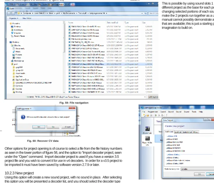
•File: in this menu you can do the following with projects: New Project, Open, Import Project (converts v3.5 projects to v4.0 projects (Project to be converted must be first saved to version 2.7.9 or version 4.7.+ software as a v3.5 file)
You can also call up the internet update facility (refer to 2.5) and close the LokProgrammer software.
During file save, all data, settings and sound files will be written into the project file. Project files are saved with the ending ”.esu“ for v3.5 decoder and .esux for v4.0
• Programmer: here you can read and write decoder data and write sound files. Extended decoder data such as type of decoder and version number of the firmware can also be read here.
Fig.12.: Menu „Programmer“
“Read Decoder Data“: Prior to changing any data on the
decoder it is advisable to read out all decoder data. Place the locomotive on the programming track and make sure the programming track is correctly connected.
Then click “Read decoder data“ in the task bar at the top of the screen. The program starts to read the data immediately. Please be patient, this process may take one or two minutes. The status is displayed in the progress bar.
“Write Decoder Data“: The CVs contained in the project file will be written onto the decoder connected to the LokProgrammer. Click „Continue“ in the window that opens first in order to write the CVs. All data on the decoder will be replaced by the new data.
“Write Sound Data“: The entire sound project will be written to the decoder using this command, replacing all sound data. Partial sound information cannot be written, therefore to use this command the project file for the decoder is required to have been opened first, using the file menu. A submenu dialog opens immediately after issuing this command: (next column)
Fig.13.: Write Sound Data „Programmer“
If “Write decoder data” is checked, the decoder data in the project will be written first, followed by sound. If “Overwrite defaults with current values” is checked, then the current decoder data will become the defaults for when the command “reset decoder,,,” is issued. When “Next” is clicked, the information write begins and will take up to 30 minutes to complete, depending on amount of sound data being written.
“Reset Decoder“: Resets decoder to either factory
defaults or current defaults if “Overwrite defaults” has previously been used.
5.3. Tools
Fig.14.: Menu „Tools“
The Tools menu provides options that provide information about the current decoder and allow you to take certain actions in regards to the current decoder you are working with: (see next page)
7
9
Main Screen page Cont.
“Supported decoders,,“: This provides a listing of all the decoders currently supported by the programming software version you are currently using.
“Export CV List,,“: Creates a .txt file and opens a file save dialog, allows you to save a listing of the current CV’s for future use, such as comparisons, etc.
“Show changed CV’s,,“: Opens a sub-dialog box that
displays a listing of only the CV’s that have been changed since the last time the project file was opened. This is extremely useful if you intend to perform an action such as manually programming a decoder. See figure 15 below:
Fig.15.: Changed CV’s, sub dialog „Tools“
“Load Control,,“: Opens a sub-dialog box that lists common DCC motors that have performance templates built into the software based on each motor type. Selecting one from this list that matches or closely matches the motor you are using in your model and provides a starting point for setting up your model. See fig 16 at top of next column:
10
Fig.16.: Load Control, sub dialog „Tools“
“Update decoder firmware“: Commands an activity that will
either confirm the current decoder is at the current firmware, or will write the current firmware to the decoder. Note, this action is also incorporated in the commands that write decoder data.
“Change decoder type“: This allows you to open a project such
as one for a LokSound Micro or Standard, and change the decoder type to another supported decoder, such as an XL. Note; it is not possible to change a decoder type from a v4 project to a v3.5, this option is reserved for working within the same decoder architecture.
“Program Settings“: Opens a sub-dialog that allows you to set or change current programmer settings; such as file
directories, languages, display CV’s, etc. This is also where com settings are controlled for communication with the LokPprogrammer hardware. See figures 17 and 18 next column:
Fig.17.: Program Settings, sub-dialog„General“
Drivers Cab, Decoder
Information, Read / Write CV’s
6. Driver’s cab
With the aid of the driver’s cab you can test decoders and sound projects. You can run the locomotive and trigger all functions. Therefore you can test run your locomotive on the programming track with the LokProgrammer.
Fig.19.: Virtual Driver’s Cab
Included in the Drivers Cab section is the Turnout Control Panel which allows you to also test the Switch Pilot decoder.
Fig.20.: Turnout Control Panel
There are some limitations though: the LokProgrammer power supply limits the permitted current to about 400 mA. Should the motor of the locomotive draw a higher current then the over current protection will be triggered and the power to the programming track will be shut off. This is indicated by the blinking yellow LED on the LokProgrammer. In this case deactivate the virtual cab and then turn it on again.
All other functions in this register are self explanatory: You can enter the address and the number of speed steps. Please make sure that the speed steps matches the ones set on the LokProgrammer.
The LokProgrammer can run locomotives in DCC format, as from version 2.5 also in the Motorola® format. Due to the hardware the LokProgrammer cannot handle M4. Test your M4 projects in the Motorola® format.
Please check that your programming track is fully isolated from the mainline of your layout prior to turning on the virtual cab. Should there be any electrical bridge it could damage the LokProgrammer (also refer to 2.2.)!
Activate the locomotive for the test run by clicking the field „Activate Cab“.
Control the speed of the locomotive with the slide throttle. Clicking into the appropriate fields turns functions on and off. Up to function F12 you may also press the numbers on your computer keyboard.
Please bear in mind that running a locomotive with the LokProgrammer cannot and should not substitute a command station: due to the limited power of the power pack you will not be able to run more than one locomotive at any one time. The virtual cab simply gives you the opportunity to quickly test run your locomotive.
7. Decoder Information, Read / Write CVs
In the register „Read / Write CVs“ you can perform 2 actions, first in the list is an icon labeled “Decoder Information” (see figure 21), when the button titled “Read decoder information” is clicked, the decoder currently connected to the programmer will be read, and the information will be displayed on the decoder information dialog as shown in figure 21.
Also within this register you can read and write individual CV’s on the currently active decoder attached to the programmer (see figure 22) , this is done as follows: Select the register „Read / Write CVs“. Then to Read a CV:
• Enter the number of the CV you want to read in the upper data entry field.
• Press the button „Read CVs“.
• The result will be shown in binary and decimal format.
Fig. 21.: Decoder Information
Fig.22: Read / Write CV’s
Write a CV:
• Enter the number of the CV you want to write in the field at the top.
• Write the new value of the CV in the lower data entry field. • Click onto the button „Write CVs“.
• The CV will be overwritten with the new value.
• The Index CV’s are also shown, and should be set correctly in order to write values correctly.
Note: Similar to POM (Program on the Main), does not change sound project values.
Change Decoder Settings
Address
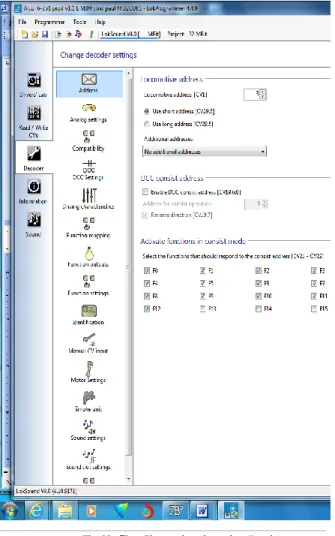
8. The “decoder settings” register
All settings regarding the motor control and CV configuration (such as Function mapping, Sound settings, DCC settings, etc.) of the decoder are handled in the “Change decoder settings” register. Please note that this Register is initially empty when you start the program. Information will only be displayed in this field after you have generated a new project, opened an existing project or read out a decoder. Projects are an image of all data stored on a decoder.
Fig. 23.: The „Change decode settings“ register
The buttons that let you go to the different options are on the left of the screen. Besides movement and sound behavior you
12
can adjust specific settings such as brake mode, address, etc. On the following pages we will explain the parameters and options.
8.1. Decoder address
8.1.1. Address (CV 1, CV 17, CV 18)
All modifications of the address are done in the window „Address“. Subject to the decoder type so called short (two digits, CV1) or long addresses (four digits, CV17 and CV18) can be used.
Please note that any settings in these CVs are only effective for operation with NMRA-DCC compliant command stations. When operating decoders with the Märklin® / Motorola®- protocol a separate address, namely the Märklin®-address is valid.
You may enter a second address for M4-decoders in Motorola® mode in order to activate F5 to F8. Normally this would be the address of the decoder plus 1.
8.1.2. Consist settings (CV 19)
The DCC consist address is useful for multiple traction. It is also possible to activate function outputs for consists as well as function buttons for consist mode.
In some cases it is desirable to set certain functions in consist mode in such a way that the function is actually triggered by pressing one button in both (or all) locomotives (e.g.: lights). Click onto the appropriate button of the function that should be activated in consist mode.
8.2. DCC / Analogue
Supported analogue modes and settings (CVs 13, 14, 50, 125, 126, 127, 128, 129, 130). In analogue mode load compensation is not active. Therefore by using the appropriate slide control you can adapt the start voltage and the maximum speed separately for AC or DC Analogue mode to match the characteristics of your motor or transformer. Furthermore you can select the functions that should be active in analogue mode (DC, AC or both; CV 50).
8.2.1. Active functions in analog mode (CV13, CV14)
Since most analogue layouts do not have input devices to trigger functions, these parameters allow you to pre-select which functions should be automatically active in analogue mode. It is recommended to turn on the sound (default value F1 for European projects, F8 for USA) and the smoke generator of steam locomotives (often F4). Also lighting should be active if desired. Checked functions cannot be controlled during analog operation, they are either on (checked), or off (unchecked).
8.2.2. AC Analogue mode (CV 29, CV50)
Activates the AC analogue mode, and allows setting of Start voltage (minimum speed) (CV127) and Maximum speed voltage (CV128).
8.2.3. DC Analogue mode (CV29, CV50)
Activates the DC analogue mode, and allows setting of Start voltage (minimum speed) (CV125) and Maximum speed voltage (CV126).
8.2.4. Analogue voltage hysteresis (CV 130, CV129)
The motor will stop when the voltage falls below start voltage minus motor hysteresis voltage. Functions will be activated when the voltage reaches the motor start voltage minus the function difference.
8.3. Compatibility
ESU v4 decoders have certain characteristics built into them to allow them to be configured to enhance operational
compatibility with certain dcc command stations. Compatibility settings are enable by checking certain boxes in the
programming software. These selection boxes are identified in the compatibility section. Options available are:
8.3.1 LGB MTS (CV49.5)
Checking this box enables serial function mode for f1 through f8 and improves compatibility with LGB Multi Train Systems command stations
8.3.2 Marklin Delta mode (CV49.2)
This option enables Marklin Delta mode in support of Marklin delta dcc systems.
8.3.3 Zimo Manual function (CV49.6)
Zimo manual function can be enabled by checking this option.
8.3.4 Serial user standard interface (CV 124.3)
Selecting this opetion will enable the decoder Serial User Standard Interface (SUSI), this will the decoder to communicate with up to 3 SUSI devices.
Change Decoder Settings
DCC Settings / Driving Characteristics
8.4. DCC Settings
There are 2 groups of items you can configure in this view window as shown in figure 24. These are RailCom settings and Speed step mode.
Fig. 24.: The „DCC Settings“ register
8.4.1 RailCom settings CV29, CV28)
These settings allow the enabling or disabling of RailCom information. Checking the first option enables RailCom feedback and allows setting the other 3 items as you desire. LokSound v4 decoders are RailCom enabled and thus offer you the features RailCom provides.
8.4.2 Speed step mode (CV49, CV29)
Here you can adjust more settings for running your locomotive. In DCC mode you have the option of setting the speed steps manually to 14, 28 or 128. Optionally you can check the first option box and allow the speed steps to be detected automatically.
8.5 Driving characteristics
Items within this view window allows the adjustment of several variables that affect overall driving features that are available, such as; acceleration and deceleration (momentum), brake options, speed trimming, and other power handling features.
Fig. 25.: The „Driving characteristics“ register
8.5.1 Acceleration and deceleration (CV3, CV4)
Selecting the check boxes for acceleration and deceleration enables and sets momentum values for speeding up and slowing down. Setting momentum values allows the model being driven to act in a more realistic manner, and it allows certain sound features to be enjoyed.
Acceleration (CV3) can be adjusted using the variable slider within a decimal value range of 1 to 255 providing acceleration times of .1 seconds up to 63.75 seconds. Deceleration time (CV4) can be adjusted using the deceleration time across the same range, allowing you to set values for coasting. Higher Momentum settings also allow certain sound features to operate realistically, such as coasting sounds and acceleration sounds.
8.5.2 Allowed brake sections (CV27, CV134, CV123)
A variety of automatic brake sections can be enabled for the v4 decoder; this allows the layout on which the decoder is running to be configured to trigger locomotive braking when a section of track is reached, perhaps a curve, and then the locomotive returns to prior speed upon exit. The various types of brake section detection are enabled by checking the boxes that match your layout(s).
ABC brake mode can be set for either right rail (CV27.0), left rail (CV27.1), or both having a more positive voltage than the other. Voltage difference (CV134) to enable the trigger can be set with a variable slider with a range of 4 to 32, providing a significant flexibility in setting up layouts. The second slider (CV123) allows setting the amount of speed reduction over a range of values from 0 – 255, allowing automatic speed reduction from very slight to a complete stop. Also available is compatibility with ZIMO (HLU) brake sections (CV27.2) by selecting the option to enable them.
You can also enable auto stop brake sections carrying a either a forward DC polarity (CV27.4) or reverse DC polarity (CV27.3) by selecting the appropriate check box.
8.5.3 Constant brake distance (CV254, CV255, CV253, CV27.7)
Constant brake distance allows you to precisely control where your trains will stop on your layout. This effect works in conjunction with brake sections, and it can be used without brake sections by setting only CV254 to determine a distance for braking, along with setting CV27 bit 7. With these settings made the v4 will generate a stop command when ever speed control is set to speed step 0. Stop distance will be based on the value set in CV254. See v4 decoder manual chapter 10.6 “Constant Brake Distance for detail.
13
14
Change Decoder Settings
Driving Characteristics / Functions
Fig. 26.: The „Driving characteristics“ register
8.5.4. Reverse mode (CV 29)
A tick at „Reverse mode“ changes the direction of travel and the directional characteristics of the headlights. This is useful in case the wiring has been done incorrectly (swapping of track
leads or motor leads).
8.5.6 Trimming (CV66, CV95)
The trim function allows you to set the maximum speed separately for forward and reverse movement. The factor that is used to multiply the motor voltage, results from dividing the CV-value by 128 (forward CV 66 and reverse CV 95).
8.5.7 Power Pack (CV 113)
V4 decoders (HO and N) provide for the installation of capacitors or power packs (so called “keep alive” devices). CV113 allows control of the amount of time the device is active. Setting range is 0 to 255 via the adjustment slider; an estimated active time is shown to the right of the setting in seconds. Information for installing capacitors or power packs can be found in the decoder manual chapters 10.9 (configuring) and 6.11 (wiring).
8.5.8 Preserve Direction (CV124.0)
Checking this option keeps the direction constant when the v4 equipped loco transitions from DCC control to Analog controlled track sections.
8.5.9 Starting delay (CV124.2)
Usually, when the LokSound V4.0 sound is idling and you turn up the throttle, the locomotive begins to move only after the Diesel engine has reached notch 1. A steam loco will even release its brakes first and fill the cylinders. Although this behavior is very prototypical, one might not like it because it causes some delay. You can control this startup delay by simply not checking this option. This will cause the LokSound V4.0 decoder to immediately start moving when the throttle is turned up. However, the start up sound will not be synchronized with the motion anymore.
8.6. Function views
Both LokSound V4.0 and LokSound micro V4.0 decoders have identical function mapping. M4 and XL decoders have different screen displays. The display will shift when the decoder type for any given project is changed; therefore, the screen display depends on decoder type. Shown here is the display for V4 standard and micro decoders. A great deal of information is available in the v4 decoder manual concerning function mapping. Of course, which sound is assigned to which sound slot may vary depending on the decoder project. You will find a list with all available project files “Download/Sound files/LokSoundV4.0/“ on our home page at www.esu.eu. You may also view and print a list with all functions and the sound slots employed.
The LokSound V4.0 decoder offers powerful and flexible function mapping options:. Each function button can switch as many outputs as desired. Each output can be activated by several function buttons. Function buttons can be linked (e.g.: F3 AND F5 pressed simultaneously)
Function buttons can be inverted (e.g.: NOT when F8 is on). Besides the buttons F0 to F28 you can also incorporate the direction of travel or the speed (locomotive is moving / has stopped)
You may connect as many as 5 external sensors. While many model train enthusiasts need precisely these functions for optimal running of all their locomotives setting up function mapping represents so to speak the “free style”
version of decoder programming. Take your time to understand the concept behind it before you start changing any settings. For a complete review of all function mapping CV’s, see the v4 decoder manual.
HINT: Even if you do not have LokProgrammer hardware, you can still use the software as an aid in making mapping changes in conjunction with the “Show changed CV’s” capability.
Fig. 27.: The „Function mapping“ register
The function mapping view is arranged as a matrix with vertical columns for conditions, physical outputs, logical functions and sounds. Horizontal rows list each condition and function key for use in mapping as desired. See figure 27.
8.6.1 Function mapping, “Conditions”
The input block (conditions block) shows which condition is required to achieve a certain output. Conditions are for instance “F3 On” or “Locomotive is stationary with direction set to forward, and F8 is switched on”. Configuring the outputs to behave as desired begins by deciding which function or function key you wish to configure to enable an output that will perform the desired action when the function is on, or off.
Change Decoder Settings
Function Mapping Cont.
The figure below; figure 28, displays an example of setting a condition against function key F11 in which the direction is set to reverse, and the key must be ON in order for the condition to equate to “true”, This then becomes the condition that must be fulfilled in order for the desired output to be enabled.
Fig. 28.: Establishing a condition for F11
In this manner all the functions available to the decoder can be configured to behave as desired. The next task is to set the desired output for the function.
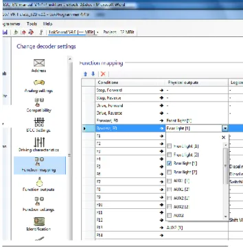
8.6.2 Function mapping, “Physical outputs”
In the output block it is shown what action must be carried out when the condition(s) is/are met. This could be, for instance, switching a function output or a sound effect. LokSound decoders have up to 12 physical function outputs. “Headlights“and “Rear lights“are used for lighting, the remaining ones are freely available. Other functions include “Shunting Mode“, “Acceleration / Deceleration On/Off“ as well as virtual functions like “Sound On/Off“. The function buttons (“F buttons“) of your command station or throttle activate the function outputs. Generally, F0 is the lighting button, while we count the remaining buttons from F1 upwards. See figure 29, next column, for an example of
configuring the Physical output for F0 to enable the rear light to come on when the condition “F0 is on and direction is reversed” becomes true.
Fig. 29.: Setting a Physical output for Rear Light
Complicated lighting configurations can be set by selecting more than 1 output. For example, we wish to have the front light on bright when running forward, and dim when running in reverse. this can be done setting front light(1) and front light(2) on, and then setting the function outputs for front light(1) as on and front light(2) as dim in the function outputs section. (See figure 30 and 31)
Fig. 30.: Setting a Physical output for Front / Rear
8.6.3 Function outputs, “Configuration”
Configuring the function outputs is done on a separate screen from the mapping portion, each output can be configured discretely, and some outputs such as Front and Rear lights, and Aux1 and Aux2 can each have 2 configurations, to satisfy certain needs, such as running with the front light on bright when going forward, and on dim when reversed. There are many configuration options available, as pictured in figures 31 and 32 dropdown menu options:
Fig. 31.: Physical output configuration for Front(2) dim
Fig. 32.: Setting a Physical output to trigger smoke chuff
16
Change Decoder Settings
Function Mapping Cont.
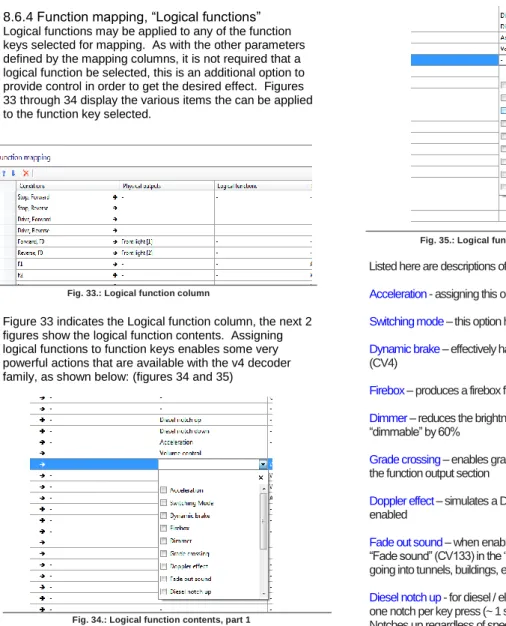
8.6.4 Function mapping, “Logical functions”
Logical functions may be applied to any of the function keys selected for mapping. As with the other parameters defined by the mapping columns, it is not required that a logical function be selected, this is an additional option to provide control in order to get the desired effect. Figures 33 through 34 display the various items the can be applied to the function key selected.
Fig. 33.: Logical function column
Figure 33 indicates the Logical function column, the next 2 figures show the logical function contents. Assigning logical functions to function keys enables some very powerful actions that are available with the v4 decoder family, as shown below: (figures 34 and 35)
Fig. 34.: Logical function contents, part 1
Note: multiple logical functions may be assigned to each function key, in this way one can fully configure a key as desired.
Fig. 35.: Logical function contents, part 1
Listed here are descriptions of each Logical function:
Acceleration - assigning this option disables momentum effects
Switching mode – this option halves speed, useful in yard operations
Dynamic brake – effectively halves the deceleration momentum value (CV4)
Firebox – produces a firebox flicker effect
Dimmer – reduces the brightness of all physical outputs that are set to “dimmable” by 60%
Grade crossing – enables grade crossing lighting effects, as configured in
the function output section
Doppler effect – simulates a Doppler sound effect based on speed when enabled
Fade out sound – when enabled fades the sound to the volume setting for “Fade sound” (CV133) in the “sound settings” section; allows simulating going into tunnels, buildings, etc.
Diesel notch up - for diesel / electric sound projects, allows notching up of one notch per key press (~ 1 sec cycle), or engage for multiple notch points. Notches up regardless of speed.
Diesel notch down – notch down as above. Note: once engaged manual
notching remains in effect until locomotive is stopped and notch point is at idle.
Shift mode - when selected sound flow path will branch on those sound flow charts where “shift” is used as a condition, such as “shift = true” (e.g. alternate start up path such as cold start, dynamic brake actions associated with dynamic brake engaged, such as engine rpm moves to idle followed by notch 4)
ESU smoke unit – when engaged will turn on smoke effects associated with intelligent smoke units, such as ESU, KM-10, Kiss and others, also standard smoke units. Note: also requires setting of appropriate function output , and smoke unit settings
Volume control – when set, allows setting volume in 6 steps by toggling the function key on and off, once per step. Changes the master volume in 6 steps (CV 62)
Disable brake sound – when engaged turns off automatic brake sound (CV459 (CV32=1))
Uncoupling cycle – turns on automatic coupler action, also requires setting
of function output coupler type and function settings section for automatic uncoupling.
8.6.5 Function mapping, “Sounds”
Here is the area of function mapping where sounds are linked to specific function keys. If sound slots have been named, the name will display in the list when expanded. You can assign multiple sounds to a single key, and you can assign sounds to multiple locations. If desired. See figure 36 below.
Change Decoder Settings
Functions / Identification / CVs
8.6.6 Function settings, “General” and “Automatic uncoupling” As mentioned in 8.6.5 above, when mapping logical functions to a function key, in some cases you should also use Function settings in order to enable the response you desire when the function key is engaged. General settings are for configuring lighting effects, and allow you to set the blink frequency for lighting situations that require blinking lights (CV112), and for setting grade crossing holding time (CV132). Holding time is the amount of time the grade crossing effect is enabled.
Automatic uncoupling is where automatic uncoupling is enabled (CV246), and where you can set the uncoupling speed across a range of 1 – 255 (same as the speed table range), default is 1 (CV246). Push time (CV248) is the time in seconds the automatic push is in effect; and Move time (CV247) is the time in seconds the locomotive moves away from the uncoupled car(s). Of course “time” relates directly to distance traveled at the speed set for the duration of the automatic uncoupling cycle. See figure 37.
Fig. 37.: Configure Function settings
8.7. Identification
8.7.1 Data fields, “User identification”
The user identification fields are open fields that can be used for any purpose. These are designated as “User ID #1” and “User ID #2”. CV’s are CV105 and CV106 respectively. Value range for both is 0 – 255 and they can be set individually or together. Setting these CV’s does not change any decoder behavior, they are an open code section and can be used for any purpose, perhaps to track a certain version, or function key structure. Default value is 0 for both CV’s. See figure 38
Fig. 38.: User Identification
8.8. Manual CV Input
8.8.1 Manual CV Input
This section of the change decoder data screens is made available should you wish to make manual CV changes without using the preformatted decoder set up screens and views. It is also very useful for researching CV’s. When you export the decoder CV listing (See “5.3 Tools”, Export CV list) the text file that is created during the export will consist of the same data displayed in this view.
8.8.2 CV changes
CV changes can be made directly by overwriting the data in any of the data fields; “Value”, “Binary”, or “Hex”, simply enter the value you wish and then tab out of the field and the data will be changed and the other two data columns will update. Of course it is much easier to enter direct numeric data in the “Value” column than it is to write Binary or Hex data.
After you are finished making changes, the new values may be written to the decoder using “Write decoder data” (See “5.2 Programmer”, Figure 12)
Note: The ability to make manual changes is very powerful and should be used with care. Consider saving the changed project file under a new name in order to provide a way to rewrite last known good data to the decoder to recover from mistakes. See figure 39.
Fig. 39.: Manual CV Input
8.9. Motor Settings
Here is where you configure speed table, load control, PWM frequency, and overload protection settings on the v4 decoder series. Information presented here deals directly with making desired settings using the LokProgrammer tool to configure the decoder, therefore the level of detail presented is not at the same level as is found in the v4 decoder manual. Please use the detailed information found in the decoder manual, chapter 10, as the preferred source for decoder information.
8.9.1 Speed table selection and configuration(CV 2, CV 5, CV 6, CV 26, and CV 67-97)
Here you may select either a 3 point speed table (figure 40) or a custom speed curve (figure 41). If you use the 3 point table you should set minimum and maximum speed (CV2 and CV5) and then pick the mid range speed (CV 6) as desired. You may also use the slider on the right hand side to set both maximum and mid range speeds. In order to avoid possible rough or unusual running, please ensure
18
Change Decoder Settings
Motor Settings
mid range speed is higher than start speed and maximum speed is higher than mid range speed (CV2<CV6<CV5).
Fig. 40: 3 point speed table
You may also define your own speed curve: simply enter the desired values in the CVs 67 to 94 (also refer to Fig. 16). The decoder will superimpose these 28 values onto the real speed steps. Thus, you can adapt the driving performance optimally to your locomotive. Another option is available using the speed curve option, there are 5 predefined speed curves stored in the programmer software, you may select any of these by simply clicking on the one you desire to start with, and then you can modify them as desired. See figure 41.
Fig. 41: Speed curve options and set up
Speed curve shape is set by adjusting the 28 point curve as desired, then minimum and maximum speed is set as it is with the speed table (CV’s 2 and 5), the decoder then fits the
Speed curve between the minimum and maximum speed settings resulting in a smooth 28 point speed curve within the decoder. Please see the decoder manual, chapter 10 for more detail.
8.9.2 Load control / Back EMF (CV’s 53, 52, 51, 55, and 56)
Load control compensation is enabled via the LokProgrammer by checking the box at the top of the load control section, following that, the CV’s can be adjusted as desired. HINT: If the decoder is installed in a model locomotive, there is an “auto set” feature you can use to set the initial parameters. See decoder manual, chapter 11 for details on how to use this feature. Then if you need further adjustment you can “read decoder data” to load the automatic settings into the programmer for fine tuning. See figure 42.
Fig. 42: Load control / back EMF setup
LokSound decoders enable you to adapt load compensation to the motor with CVs 53, 54 and 55. If the recommended values above do not lead to acceptable results, you can further optimize them. Especially for the slow driving sector (speed step 1) the LokSound V4.0 with CV 51 and CV 52 to change the gain control. This helps to avoid any jerking while driving extremely slowly.
Parameter K, stored in CV 54, influences how strongly load control will affect the driving performance. The higher the value, the more load control will respond to any changes and try to adjust the revs of the motor. Parameter K needs adjustment if the locomotive runs unevenly (jerks). Reduce the value of CV 54 by 5 and test-run the locomotive to see if there are any improvements. Repeat these steps until the locomotive runs smoothly at speed step 1. Parameter I, stored in CV 55, provides important information to the decoder on how much inertia the motor has. Motors with large
flywheels naturally have more inertia than smaller ones or coreless motors. Adjust parameter I if the locomotive jerks somewhat just before it stops or jumps at lower speeds (lower third of the speed step range) or simply does not run smoothly. Increase the value by 5 starting with the initial value for motors with very small or no flywheels. Reduce the value by 5 starting with the initial value for motors with large flywheels. Test again and repeat this procedure until you arrive at the desired result. In CV 53, you set the EMF reference voltage generated by the motor at maximum revs. This parameter may have to be adapted subject to the track voltage and the efficiency of the motor. If the locomotive reaches maximum speed when the throttle is set to about three-quarter and the top third of the throttle has no influence on the speed, then you should reduce the value of CV 53. Reduce the value by 5 – 8 and test the locomotive again. Repeat this process until the locomotive just reaches its maximum speed when the throttle is fully open. On the other hand, if the locomotive moves too slowly at full throttle then you should increase the value of CV 53 step by step until the maximum speed is reached.
Together with the LokSound V4.0 decoder an additional CV 52 has been introduced which separately determines the gain control considerably for the whole slow driving sector in speed step 1. If you are not satisfied with the driving behavior when the locomotive drives slowly or starts, while everything is fine with the medium and high speed steps, you should increase the value of CV 52 by 5 - 10 higher than the value set in CV 54. Here you can adjust the inertia of the motor separately for slow speeds and starting from a stop. The desired value is to be entered into CV 51. The parameters “K slow” and “I slow” jointly influence the behavior at speed steps 1 and 2 while the parameters CV 54 (“K) and CV 55 (“I”) are responsible for the remaining speed steps. The decoder computes a speed curve in order to avoid any abrupt changes.
The decoder operates ex works with a mutable (adaptive) regulation frequency to drive the motor as precisely as possible. However, as a result some motors might show a nasty buzzing noise. For such motors you are able to set the regulation frequency on a constant value by checking the box to enable adaptive regulation frequency. You may also adjust the Back EMF sampling period using the slider, values range from 4 to 8 (CV10).
Fig. 43: Load control preset motors
You may apply presets that have been tested by ESU for many types of motors by clicking the option “use motor control values from preset motor types “ See figures 42 and 43. See v4 decoder manual for mote detail.