Illumination Requirements for
Roadway Visual Tasks
H. RICHARD BLACKWELL, B.S. PRTTCHARD*, and RICHARD N . SCHWAB, Insti-tute f o r Research in Vision, Ohio State University, Columbus
• B L A C K W E L L (1) has recently reported a general quantitative method f o r establish-ing the illumination levels required f o r adequate performance of various visual tasks encountered in interior environments. Inasmuch as there are no significant visual factors involved i n performing outdoor tasks which are not also involved i n performing interior tasks, the general method should be useful in establishing illumination levels for outdoor as well as indoor visual tasks. The present paper reports the establish-ment of illumination levels required f o r the performance of typical visual tasks involv-ed i n night driving, on the basis of the 1959 method. Of course, there are always spec-ial problems involved in the application of any general method i n a new connection and in this case, new procedures and instrumentation were required f o r use of the method with roadway visual tasks. However, the basic assumptions and data used i n connec-tion with roadway visual tasks are identical with those used previously i n connecconnec-tion with interior tasks.
THE LIGHTING SPECIFICATION METHOD
For the present purpose, a brief summary of the method proposed i n 1959 f o r estab-lishing illumination levels f o r various visual tasks w i l l suffice.
An extended study was f i r s t made of the quantitative performance of normal young observers when presented visual tasks varying i n size and contrast at various levels of background or adaptation luminance. In one series, the observers were not required to search and scan f o r the task, but were presented their tasks under optimal condi-tions i n order to maximize their performance. Visual capacity to p e r f o r m the tasks was determined f o r various durations during which the task might be presented. This study revealed the background o r adaptation luminance value required to p e r f o r m a visual task of fixed size and contrast during a fixed exposure t i m e . Data were avail-able f o r various quantitative levels of performance accuracy.
Study of patterns of eye movements during continuous visual work reveals that the normal eye w i l l pace itseU at a rate of about 5 fixational pauses per second. On this basis, i t was decided that the visual system would be provided a reasonable level of "visual capacity" if i t were enabled to assimilate one item of visual information per fixational pause. The c r i t e r i o n level of visual performance built into the lighting spec-ification system was established as a visual capacity of 5 assimilations per second (APS), at an accuracy level of 99 percent.
Of course, observers must usually search and scan f o r visual information under f a r less than optimum conditions. A second series of studies required the observers to p e r f o r m visual tasks under realistic conditions of search and scanning. Performance data obtained under these conditions were compared with s i m i l a r data obtained under the optimum conditions studied previously. It was found that allowance could be made for the differences between the realistic dynamic conditions and the optimal conditions by use of a " f i e l d factor" of 15, representing that fifteen times more task contrast is required in the one case than in the other. It was assumed that the conditions of the dynamic experiments were reasonably typical of use of the eyes i n various actual tasks. Therefore, a factor of 15 was used i n adjusting the absolute values of the original data f o r the purposes of the lighting specification system.
A standard performance curve was then derived f o r the visual task consisting of a Deceased Aug. 26, i960.
118
VISUM. CWaOTT S APS
99% KCURKy FCLO raCTOB 19
NO nSaaUTY CLME
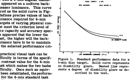
bright disc with a 4-min a i ^ l a r diame-ter, which appeared on a uniform back-ground of lesser luminance. This curve is reproduced as the solid curve i n F i g -ure 1. It defines precise values of back-ground luminance required f o r 4-min standard targets of v a r y i r ^ physical con-trast to just meet the criterion level of performance capacity and accuracy spec-ified. It is apparent that the lower the task contrast, the higher w i l l the back-ground luminance have to be to maintain the task at the selected performance c r i -terion.
Now, a practical visual task can be rated i n difficulty i n terms of the specif-ic physspecif-ical contrast value f o r the 4-min standard task which makes the two tasks of equal difficulty. Once such an equivalence has been established, the p e r f o r m -ance curve f o r the 4-min standard task may be used to establish the precise
background luminance needed to maintain the practical task at the performance c r i t e -r i o n . Requisite illumination may be computed f -r o m the value of -requi-red luminance f r o m measurements of the reflectance characteristics of the task. The equation be-tween standard and practical tasks is made i n an instrument known as the Visual Task Evaluator (VTE). The device reduces both the standard and practical tasks to near the visibility threshold so that a reasonably precise equivalence can be established. After assessment with the VTE, the d i f f i c u l t of each practical task may be described fully by a value of "equivalent contrast" f o r the standard task found to have equal dif-ficulty. Only one value of background luminance and hence one value of illumination can provide the criterion level of visual performance f o r each practical task.
The original report of the lighting specification method included a statement con-cerning its use under circumstances i n which there is substantial disability glare i n the f i e l d surrounding the visual task. The basic idea goes back to an earlier paper by Blackwell (2). Blackwell has shown that the disability glare effect can be intro-duced into visual performance data such as those presented i n the solid curve in Fig-ure 1 by constructing curves such as the dashed one shown i n the same f i g u r e . This curve represents a value of K = 2 i n which
Figure 1. Standard performance data for a l|-min disc target. Solid curve represents no d i s a b i l i t y glare. Dashed l i n e repre-sents a degree of d i s a b i l i t y glare as
de-scribed i n the text.
K B + By B — (1)
in which
B = luminance of the task background i n the absence of disability glare; and Bv = total equivalent luminance produced by a l l sources of disability glare
within the f i e l d .
It i s possible to construct a performance curve f o r any value of K of interest by geo-metrical construction i n only a few minutes, following the method described (2).
Of the several e3q>ressions f o r By extant, the authors prefer the one reported by Fry (3) which may be written
B v
= E
1 = 1
10 E l
d i ( d i + i.5) (2)
in which
Ei illumination produced by a point glare source on the entrance pupil of the eye; and
119 9 i = the angle between the point glare source and the line of sight of the eye,
measured in degrees. The value of 9 i must always equal or exceed 1 deg.
Of course, i t would be possible to compute the value of By f o r the environment of each visual task of interest, but i t would hardly be practical. Instead, the authors have de-veloped the idea suggested earlier by F r y (4) that a photoelectric photometer be used in obtaining a value of By immediately f r o m the environment surrounding a visual task.
EXPERIMENTAL APPARATUS AND PROCEDURES
In addition to standard items of photometric equipment, three special items of meas-urement equipment were used. These are shown in Figure 2 i n the outdoor site used f o r measurements at Hendersonville, North Carolina. The large optical device on the right is the VTE. The telescopic device on the tripod to the left is a Pritchard Photo-electric Photometer. What looks like an extra lens near the foremost leg of the tripod is the attachment used to obtain values of By by physical measurement.
The Pritchard photometer consists of a telescope and photomultiplier tube, arranged so that the photometer measures the luminance of small distant areas. The attachment f o r measuring By represents a "bug-eye lens" which images a f u l l 180-deg view of the environment in the plane of a photographic absorptive mask. The lens was designed and built by F r y , whereas the authors have prepared the absorptive mask. The mask was designed to weight incoming flux f r o m various portions of the environment in ac-dordance with Eq. 2. An opaque mask obscured the inner 2-deg diameter of the f i e l d .
F i g u r e 'd. BpeclaJ. o p t i c a l equipment used I n t h e measurements: t h e V i s u a l Task E v a l u -a t o r -a t t h e r i g h t ; t h e P r i t c h -a r d P h o t o e l e c t r i c Photometer -a t t h e l e f t .
120 • • I
Thus, the photometer automatically integrated components of disability glare f r o m a l l portions of the environment f o r a particular visual task and gave an experimental value of By.
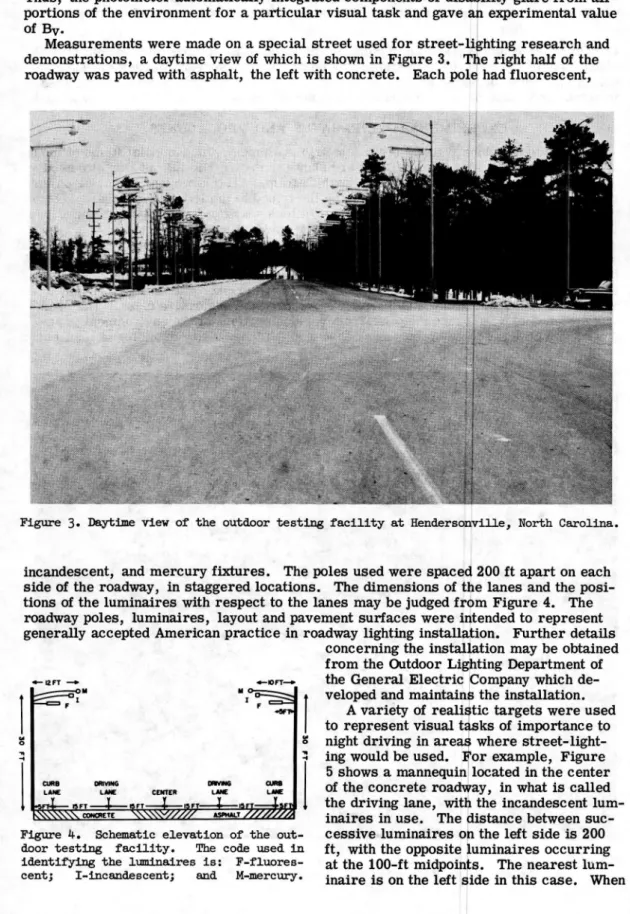
Measurements were made on a special street used f o r street-lighting research and demonstrations, a daytime view of which is shown i n Figure 3. The right half of the roadway was paved with asphalt, the left with concrete. Each pole had fluorescent.
Figure 3. Daytime view of the outdoor testing f a c i l i t y a t Hendersonville, North Carolina.
incandescent, and mercury f i x t u r e s . The poles used were spaced 200 f t apart on each side of the roadway, i n staggered locations. The dimensions of the lanes and the posi-tions of the luminaires with respect to the lanes may be judged f r o m Figure 4, The roadway poles, luminaires, layout and pavement surfaces were intended to represent generally accepted American practice in roadway lighting installation. Further details
concerning the installation may be obtained f r o m the Outdoor Lighting Department of the General Electric Company which de-veloped and maintains the installation,
A variety of realistic targets were used to represent visual tasks of importance to night driving in areas where street-light-ing would be used. For example, Figure 5 shows a mannequin located i n the center of the concrete roadway, in what is called the driving lane, with the incandescent l u m -inaires in use. The distance between suc-cessive luminaires on the left side is 200 f t , with the opposite luminaires occurring at the 100ft midpoints. The nearest l u m -inaire is on the l e f t side i n this case. When
CURB LANE omvHW L i W E i CEKTER n W M G am
Figure k. Schematic elevation of the
out-door t e s t i n g f a c i l i t y . The code used i n identifying the luminaires i s : F-fluores-centj I-incandesF-fluores-centj and M-mercury.
,,_ • 121 the asphalt pavement was used, the arrangement of lumlnaires was reversed left to
right so that in this second case the nearest luminaire was on the right side. For most measurements, there was a total of six lumlnaires but the arrangement of f i v e shown in the figure was employed in the earliest studies. With an approximately 30-ft mounting height, there were non-uniformities in pavement luminance as may be noted in the figure.
Illumination data f o r various locations along the roadway is required. These were obtained at 20-ft intervals down the roadway with a Macbeth niuminometer and stand-ard test plate.
The basic procedure may be described briefly, as follows: A target, such as the mannequin, was set up at a given location on the roadway. The measurement equip-ment was set up either i n a mobile shed or i n the back of a closed truck at a known distance f r o m the target. The VTE was used to assess the difficulty of the target ex-actly as it would appear to a driver proceeding along the roadway. F r o m this assess-ment, a value of the equivalent contrast of the 4-min standard target was obtained.
The Pritchard photometer was f i r s t used to measure the average luminance of an area of the environment containing the target, having a 2-deg diameter. The disabil-ity glare attachment was then placed on the Pritchard photometer and a value of By
was obtained corresponding to the case of an observer viewing the target ahead. Subsequently, a performance curve (such as the dashed curve in F i g . 1) was con-structed f o r the value of K corresponding to the experimental values of B and By. The value of equivalent contrast obtained in the VTE was entered on the ordinate and the
F i g u r e 5. Night-time view o f t h e outdoor t e s t i n g f a c i l i t y w i t h t h e mannequin t a r g e t seen against the concrete pavement.
122
point of intersection with the appropriate (dashed) performance curve was used to de-fine the precise bac1q;round luminance level required for adequate performance of the visual task, in the presence of the measured amount of disability glare.
While in the field, measurements were made of the actual Illumination falling on a test plate oriented horizontally. The requisite horizontal illumination was obtained from the relation
E r = E o
| j
(3)
in which
Eo = the horizontal illumination actually obtained;
Bj. = the luminance required for adequate performance of the task; and B Q = the average luminance of task and surround actually obtained.
Eq. 3 is actually no more than a method for determining the reflectance of some por-tions of the pavement for illumination coming from luminaires in a particular position with respect to the target.
EXPERIMENTAL DATA
It was intended that as good a sample as possible of typical roadway visual tasks be invest^ted. Nine tasks were originally selected for evaluation, in order to obtain some idea of their relative difficulty. Measurements were made on asphalt, with in-candescent luminaires. Viewing distances of 180 and 200 f t were used and the results were averaged. The location of the measuring equipment was fixed inasmuch as it was mounted within a wooden shed. The target appeared either 40 or 60 f t beyond the first luminaire on the same side.
Illumination values required for nine different tasks are given in Table 1, in order of task difficulty. K is apparent that the illumination level required for roadway
light-TABLE 1
REQUIRED ILLUMINATION LEVELS FOR NINE TASKS^
Horizontal Illumination Task Description
1. Old automobile 0.341 2. Mannequin, with clothing of 60% reflectance
Mannequin, with clothing of 20% reflectance 0.358 3. Mannequin, with clothing of 60% reflectance Mannequin, with clothing of 20% reflectance 0.414 4. Yellow cone marker 0.436 5. Toy dog, with light fur 1.52 6. Toy dog, with black fur 1.80 7. Overturned bicycle 10.8 8. Brick obstacle 926. 9. Simulated hole in pavement >1000.
^Asphalt pavement, incandescent luminaires, 180- and 200-ft viewing distances. ing varies enormously depending on whether the task is as large and easy to see as an automobile, or as small and difficult to see as a simulated hole in the pavement. The range of illumination values covers the limits of modern roadway lighting at one ex-treme and modern interior lighting at the other. These values emphasize the signifi-cance of specifying a particular visual task when considering illumination requirements.
After completing these measurements, the authors decided to concentrate their ad-ditional measurements on two targets, the mannequin with 20 percent clothing and the black dog, —targets which seemed to be of particular importance to safety in night driv-ing in urban areas where roadway lightdriv-ing would normally be used. It will be noted
123 from Table 1 that the selections fall near the middle of the original nine tasks in terms of difficulty so that these tasks are by no means extreme.
Because individual roadway installations wUl vary in the type of luminaire and pave-ment surface used, the effect of these two variables on the illumination required for adequate visibility of the mannequin and the dog was next studied. These measurements were made at viewing distances of 180 and 200 f t with the same fixed location with re-spect to the luminaires as before.
Data relating to the effect of luminaire type are given in Table 2. It appears that there is a small difference in the requisite illumination which depends on the luminaire type, with the least illumination being required with incandescent luminaires. On the average, 6 percent more illumination is required for fluorescent and 27 percent more when mercury luminaires are employed. These differences are perhaps not large, but they will be used in analyzing the data to avoid data bias due to luminaire type.
TABLE 2
EFFECT OF LUMINAIRE TYPE ON REQUIRED ILLUMINATION LEVELS^ Incandescent Mercury Fluorescent
(a) Mannequin 0.218 0.432 0.339 0.274 0.498 0.429 0.318 0.654 0.509 0.374 0.852 0.601 0.395 1.31 0.677 0.463 1.48 0.920 0.471 0.871 ft-c 0.579 ft-c 0.472 0.871 ft-c 0.474 0.482 0.598 1.32 0.488 ft-c (b) Dog 0.481 0.517 0.873 0.558 0.636 1.02 0.664 0.692 1.17 0.664 0.875 1.21 0.780 1.83 1.40 1.10 2.96 1.46 1.10 1.25 ft-c 1.19 ft-c 1.10 1.25 ft-c 1.32 1.33 2.16 2.98 1.16 ft-c
^Asphalt and concrete pavements, 180- and 200-ft viewing distances. All values are horizontal illumination (foot-candles).
The data relating to the effect of pavement surface are given in Table 3. Here, as ej^ected, the effect of pavement type is different in direction for an object such as the dog which is of lower reflectance than either the asphalt or concrete and an object such
124
TABLE 3
EFFECT OF PAVEMENT TYPE ON REQUIRED ILLUMINATION LEVELS* Asphalt Concrete
(a) Mannequin
as the mannequin which has a reflectance intermediate between that of asphalt and con-crete. The dog is easier to see on concrete because i t more nearly matches the as-phalt in reflectance. There is little difference in the visibility of the mannequin on the two pavements because she differs in reflectance to about the same extent from either asphalt or concrete.
It was decided to standardize on an as-phalt pavement and incandescent luminaires for the next series of measurements. In this series, the viewing distance was fixed at 200 f t , and both the targets and the meas-uring equipment were moved along the road-way, so that the targets would be viewed under different geometries with respect to the luminaires. The targets were placed at locations 20 f t apart. A total of eleven positions was used, the first and last of which represented the case where the tar-gets were directly under the luminaires. One of th^ eleven locations corresponded exactly to that used in the earlier studies. Illumination values f o r each of the eleven locations are given in T ^ e 4, with the values for the location used in the earlier studies starred in each case. S is apparent that by chance a location was selected for the first studies which required the least illumination of any possible location, fi is also apparent, as expected, that the loca-tion of the tai^ets with respect to the lum-inaires has a considerable effect upon the illumination requirement. The average values in Table 4 should represent the most reasonable values to use f o r the selected luminaire and pavement conditions, be-cause there is equal interest in providing adequate visibility for all positions of a pedestrian or dog with respect to the lum-inaires.
The best over-all illumination value for a 200-ft viewing distance would presumab-ly consist of a composite value for all pos-sible types of luminaires and both types of pavement surface. Such an over-all value
may be estimated by using the data con-tained in Table 4, together with data given in Tables 2 and 3. There is reasonable supposition that the relative values obtain-ed in the earlier studies and given in Tables 2 and 3 can be applied to the data presented in Table 4 to estimate what would have been obtained had all locations of the targets un-der all luminaires and with both pavements been studied. The average values of Table 4 are first correctedf or the bias introduced because the illumination requirement is less f o r incandescent luminaires than for f l u -orescent or mercury luminaires. A multiplying factor of 1.11 corrects the values ob-tained with incandescent luminaires to the values to be e]q>ected from equal numbers of the three types of luminaires. A multiplying factor of 1.05 corrects data for the
0.218 0.274 0.374 0.318 0.395 0.339 0.429 0.463 0.432 0.471 0.472 0.498 0.474 0.509 0.482 0.598 0.601 0.677 0.654 0.852 0.920 1.31 1.48 1.32 0.577 ft-c 0.636 ft-c Concrete/asphalt factor = 1.10 (b)Dog 0.875 0.481 1.02 0.517 1.10 0.558 1.10 0.636 1.10 0.664 1.17 0.664 1.32 0.692 1.40 0.780 1.83 0.873 2.16 1.21 2.96 1.33 2.98 1.46 1.58 ft-c 0.822 ft-c Concrete/asphalt factor = 0.519 ^Incandescent, fluorescent, and mercury luminaires, 180- and 200-ft viewing dis-tances. All values are horizontal illum-ination (foot-candles).
125 TABLE 4
REQUIRED ILLUMINATION LEVELS FOR TASKS AT ELEVEN LOCATIONS* Mannequin Dog 0.415* 0.816 0.534 1.63 0.556 1.65 0.688 1.90 0.726 1.91 0.796 2.25 1.28 2.62 1.82 3.08 2.62 3.10 3.44 3.26 3.60 4.63 1.50 ft-c 2.44 ft-c * Asphalt pavement, incandescent lumin-aires, 200-ft viewing distance. All val-ues are horizontal illumination (foot-can-dles).
* Location studied previously.
mannequin obtained with asphalt alone to the average to be ejected from equal numbers of concrete and asphalt pavements. A factor of 0.76 corrects data for the dog from asphalt to an average of both types of pavements. The resulting values of requisite illumination are as follows:
Mannequin 1.74 foot-candles Dog 2.06 Average 1.90
The value of 1.90 foot-candles represents the best estimate of the illumination re-quirement for the average of the two tasks, when viewed from a 200-ft distance, with equal numbers of each luminaire and pave-ment condition.
It should be apparent from the foregoing that the illumination requirement varies considerably depending on the luminaire, the pavement, the visual task, and the lo-cation of the task with respect to the lum-inaires. Thus, an average value of 1.90
DATA FOR GIRL AND DOG COMBINED
foot-candles may be difficult to interpret. For this reason, a frequency distribution has been calculated to illustrate the per-cent of times the mannequin or dog will be adequately visible for various possi-ble illumination values.
A cumulative frequency distribution is presented in Figure 6. It was con-structed as follows: Each value in Table 4 represents a task (either mannequin or dog) at some location with respect to the luminaires, there beir^ 22 tasks in all. The factors in Tables 2 and 3 provide a basis for estimating the illumination re-quirements for each of these tasks for each of the three luminaire and two pave-ment types. Each value in Table 4 was multiplied by a factor for each luminaire type and another for each pavement type, so that there were considered to be 6 times 22 tasks in all. The distribution curve in Figure 6 represents a cumula-tive tally of the 132 illumination values
obtained in this way. (Inasmuch as the curve is skewed, a 50 percent value is obtained at a value somewhat less than the value of 1.90 obtained previously as the average value.) tt is apparent that nearly 6 foot-candles will be necessary in order to provide adequate visibility for all possible instances in which either the mannequin or dog could occur at a 200-ft viewing distance.
Usii^ precisely the same techniques, measurements have also been made at seven viewing distances other than 200 f t , ranging from 180 to 400 f t . Incandescent lumin-aires and asphalt pavement were again used. All eleven target locations with respect to the luminaires were studied at each distance. The average data are presented in
HCRIZOmitL ILLUMINATION IN DRIVING LANE (FT-CI Figure 6. Prequency dlstrll>utlQn of per-cent of times either the mannegulzi or dog w i l l be adequately viBible as a function
126
Figure 7, relative to the average illum-ination value obtained at a viewing distance of 200 ft. It is evident that the i l -lumination requirement increases as viewing distance increases with a com-paratively small change between 180 and 280 ft, but with a very rapid increase as viewing distance increases beyond 280 f t . A value of nearly 5 times as much illum-ination is required at 300 as at 200 ft, and more than 25 times as much is re-quired at 400 as at 200 f t .
A few measurements have been made in which the targets were placed in the curb lane. Both pavement types were in-volved, but only incandescent luminaires were used. Viewii^ distances of both 180 and 200 f t were used. In each case, a curb-lane measurement was always pair-ed with a driving-lane measurement un-der the same conditions. The data ob-tained are given in Table 5. It is appar-ent that nearly three times more illumin-ation is needed when the targets are in
TABLE 5
REQUIRED ILLUMINATION LEVELS FOR TASKS IN CURB AND DRIVING
LANES^
Curb Lane Driving Lane (a) Mannequin 0.399 0.498 1.75 4.29 0.374 0.395 0.472 1.32 1.74 ft-c 0.640ft-c Curb/drivii^ factor = 2.72 (b)Dog 0.810 0.930 0.985 2.28 2.58 17.6 Curb/driving 0.664 0.664 1.10 1.32 1.33 2.98 4.20 ft-c factor = 3.14 1.34 ft-c
Average curb/driving factor = 2.93 ^Asphalt and concrete pavements, incan-descent luminaires, 180- and 200-ft viewing distances. All values are hori-zontal illumination (foot-candles).
DOR FOR an. ANO DOS COMBNED ILLUMINATION OF I FOR 2 0 0 FOOT VISBIUTY DISXUICE
240 2 M ISO
viaauTY osiwicE (FEET)
Figure 7. Relation between r e l a t i v e I l -lumination and distance t o the targets.
the curb lane than when they are in the driving lane. This result is not due to the fact that illumination is less in the curb lane to begin with, but reflects the fact that the visual task is more difficult due both to confusion introduced by trees and obstacles along the roadway and due to disadvantageous luminance distribu-tions.
SUMMARY AND DISCUSSION Rather extensive illumination data have been presented for each of two roadway visual tasks; that is, seeing a mannequin and a black dog at various distances down the roadway, with a variety of luminaire types and pavement surfaces. All meas-urements have been made under an illum-ination geometry which is representative of generally accepted practice in this coun-try. The data suggest that an average value of 1.90 foot-candles of horizontal illumin-ation is required for adequate visibility of these targets when they appear in the drlv-i drlv-i ^ lane 200 f t ahead. Nearly three tdrlv-imes this much illumination, or nearly 5.7 foot-candles will be required for the same
tar-127 gets to be adequately visible at the same distance when they appear in the curb lane. S the targets must be seen 300 f t ahead in the driving lane, more than 9 foot-candles of illumination will be required and for 400-ft visibility in the driving lane nearly 48 foot-candles wUl be required. Preliminary measurements indicate that there are
more difficult roadway visual tasks than these, which will require even higher levels of illumination.
These data reveal that there are visual tasks in night driving of sufficient difficulty so that interior levels of illumination will be required if these tasks are to be ade-quately performed. These results should not be surprising because the factors of small size, low contrast, and short viewir^ time will result in difficult visual tasks whether indoors or outdoors, and high illumination levels simply are required for ade-quate performance of such tasks. The present data do not suggest that impractical levels of roadway lighting are to be recommended for practical use, but they do pro-vide a basis for evaluating what kinds of gains in visibility and hence improvements in the safety of night driving are to be expected with various increases in roadway illum-ination.
One caution must be observed in interpretir^ the present data. It has been shown that the required illumination levels depend importantly on the geometry of illuminat-ing visual tasks. The interpretations of required illumination levels will be abso-lutely accurate only if these levels are provided with an illumination geometry identical to that studied in the tests. It is manifestly impossible to produce horizontal i l -lumination of 48 foot-candles with the mounting heights and pole spacing involved in the tests although i t is possible to approach 5 foot-candles with a similar lighting lay-out. Inasmuch as the visual task may be more visible with the geometry required to produce higher levels than with the geometry studied, it is unsafe to place even scien-tific significance on illumination values in this report exceeding 5 foot-candles. It is to be hoped that illumination geometries can be discovered which will provide the de-sired visibility of the more difficult visual tasks with considerably lower illumination levels than the very high values suggested in this report. Efforts in this direction should be encouraged in every possible way.
ACKNOWLEDGMENTS
This work was supported by Grant #30-G from the Illuminating Ei^neering Re-search Institute of New York. Valuable technical guidance was provided during the conduct of the research by the Roadway Lighting Committee of the niuminatii^ Engi-neering Society. The authors are considerably indebted to the Outdoor Lighting De-partment of the General Electric Company for the use of the Hendersonville outdoor lighting facility. They also gratefully acknowledge the invaluable assistance given by Glenn A. Fry of the School of Optometry at Ohio State University.
REFERENCES
1. Blackwell, H. R., "Development and Use of a Quantitative Method for Specification of Interior Illumination Levels on the Basis of Performance Data." I l -ium. Eng., 54:317-353 (1959).
2. Blackwell, H. R., "Use of Performance Data to Specify Quantity and Quality of In-terior Illumination." nium. Eng., 50:286-298 (1955).
3. Fry, G.A., "A Re-evaluation of the Scattering Theory of Glare." Ilium. Eng., 49:98-102 (1954).
4. Fry, G.A., "Measuring Disability Glare with a Portable Meter." Proc., 2nd Re-search Symposium, nium. E i ^ . Res. Inst., Dearborn, Mich. (1958).