Hardware Installation and Setup Guide
Information in this document is subject to change without notice. Companies, names, and data used in examples herein are fictitious unless otherwise noted. No part of this document may be reproduced or transmitted in any form or by any means, electronic or mechanical, for any purpose, without the express written permission of Citrix Systems, Inc.
©2009 Citrix Systems, Inc. All rights reserved.
Citrix and ICA (Independent Computing Architecture) are registered trademarks and Citrix Access Gateway is a trademark of Citrix Systems, Inc. in the United States and other countries.
1 How to Use This Guide...7
About This Guide. . . .8
Documentation Conventions. . . .8
Related Documentation. . . .9
To view the documentation. . . .9
Getting Support and Training. . . .9
Subscription Advantage. . . .10
Knowledge Center Alerts. . . .10
Additional Maintenance Support. . . .10
Silver Maintenance Option. . . .10
Gold Maintenance Option. . . .11
Education and Training. . . .11
2 Introducing the Access Gateway Hardware...13
Access Gateway Hardware Platforms. . . .14
Access Gateway Standard Edition Hardware. . . .15
Citrix 2010 Appliance. . . .15
Access Gateway Enterprise Edition Hardware. . . .16
Citrix 7000 Appliance. . . .17
Citrix 9010 Appliance. . . .18
Citrix 10010 Appliance. . . .20
Citrix MPX 5500 Appliance. . . .22
Common Enterprise Edition Hardware Components. . . .23
Cautions and Warnings. . . .29
Power Supply Precautions. . . .29
Appliance Precautions. . . .30
Clearance Precautions. . . .31
Rack Precautions. . . .31
3 Installing Standard Edition Hardware...33
Unpacking the Citrix Standard Edition Appliance. . . .34
Preparing the Site and Rack. . . .34
Site Requirements. . . .34
Rack Requirements. . . .35
Getting Ready to Install the Access Gateway. . . .35
Materials and Information Needed for Installation. . . .35
Selecting a Location for the Access Gateway. . . .36
Setting up the Access Gateway Hardware. . . .36
To physically connect the Access Gateway. . . .37
Installing the 2010 Appliance. . . .37
Identifying the sections of the rack rails for the 2010 appliance. . . .37
To identify the sections of the rack rails for the 2010 appliance. . . .38
Installing the 2010 Appliance in a Four-Post Rack. . . .38
To install the inner rail extension. . . .38
To install the outer rails to the rack. . . .39
To install the appliance in the rack. . . .40
Installing the 2010 Appliance in a Two-Post Rack. . . .41
Turning on the Appliance. . . .42
To turn on the appliance. . . .42
Initial Configuration of the Standard Edition Appliance. . . .43
Configuring TCP/IP Settings using the Serial Console. . . .43
To configure initial TCP/IP settings using a serial cable. . . .44
4 Installing Enterprise Edition Hardware...45
Preparing for Installation. . . .46
Unpacking the Citrix Enterprise Edition Appliance. . . .46
Preparing the Site and Rack. . . .47
Site Requirements. . . .47
Rack Requirements. . . .47
Rack Mounting the Appliance. . . .47
Installing the Rails. . . .48
To remove the inner rails from the rail assembly. . . .48
To attach the inner rails to the appliance. . . .48
To adjust the length of the rail assembly. . . .49
To install the rack rails. . . .49
Mounting the appliance. . . .50
To install the appliance in the rack. . . .50
Installing and Removing the SFP Transceivers. . . .51
To install a copper SFP transceiver. . . .52
To install a fiber SFP transceiver. . . 53
Removing an SFP Transceiver. . . 54
To remove an SFP transceiver. . . 54
Connecting the Cables. . . .54
Connecting the Ethernet Cables. . . .54
To connect an Ethernet cable to a 10/100/1000BASE-T port or 1-Gigabit SFP copper transceiver. . . 55
To connect the Ethernet cable to an SFP fiber or XFP transceiver. . . 55
Connecting the Console Cable. . . 55
To connect the console cable to a workstation, laptop, or terminal. . . 56
Connecting the Power Cable. . . 56
To connect the appliance to the power source. . . .56
Turning on the Appliance. . . .57
To turn on the appliance. . . 57
Initial Configuration of the Enterprise Edition Appliance. . . 58
Using the Serial Console. . . .59
To configure initial settings using a serial console. . . .59
Using the Setup Wizard. . . .60
To configure initial settings using the Setup Wizard. . . 61
Auto-configuring an Appliance. . . .61
To set up a Linux/Unix DHCP server for appliance auto-configuration. . . .62
To set up auto-configuration on the appliance when the configuration file (ns.conf) is not present. . . 62
To set up auto-configuration on the appliance when the configuration file (ns.conf) is present. . . .63
Accessing an Appliance using SSH Keys and No Password. . . .64
To generate the public/private key on a Linux client. . . .64
To copy the public key (id_rsa.pub) to the remote appliance. . . .64
To set up secure shell access with public key encryption on the appliance. . . 64
How to Use This Guide
Topics:
• About This Guide
• Documentation Conventions • Related Documentation • Getting Support and Training
Before you install your hardware, take a few minutes to review this chapter and learn about related documentation, other support options, and ways to send us feedback. The Citrix Access Gateway Hardware Installation and Setup
Guide describes the installation and initial configuration for
the Citrix hardware models and platforms in the Access Gateway product line.
This guide is intended for service technicians who install the Access Gateway and for administrators who need to
troubleshoot the Access Gateway hardware.
The concepts and tasks described in this guide require that you have a basic understanding of server platforms, network concepts, and terminology.
Important: Before installing the Access Gateway, review the Access Gateway Standard Edition Pre-Installation Checklist or the Access Gateway Enterprise Edition Pre-Installation Checklist. The checklist provides a single place to record the necessary information for successfully setting up the Access Gateway.
About This Guide
The Citrix Access Gateway Hardware Installation and Setup Guide provides the following information about the Citrix hardware models and platforms in the Access Gateway product line.
w Introducing the Access Gateway Hardware on page 13. This chapter describes the Citrix hardware platforms and provides detailed information about each model and its componets.
w Installing Standard Edition Hardware on page 33.This chapter describes how to install the Citrix Access Gateway Standard Edition appliance, starting with unpacking the appliance and preparing the site and rack, to installing the rails, mounting the hardware, connecting the cables, and turning on the appliance, to performing initial configuration of the appliance.
w Installing Enterprise Edition Hardware on page 45. This chapter describes how to install the Citrix Access Gateway Standard Edition appliance, starting with unpacking the appliance and preparing the site and rack, to installing the rails, mounting the hardware, connecting the cables, and turning on the appliance, to performing initial configuration of the appliance and assigning management and network IP addresses.
Documentation Conventions
Citrix product documentation uses the following typographic conventions. Presentation or Convention Description
User interface controls Names of buttons, boxes, options, or other controls in the user interface.
Command names Names of commands, such as ipconfig.
Variable names Variable placeholders for information you provide. For example, filename means you type the actual name of a file.
Terms Terms newly introduced or otherwise emphasized.
Code examples Text displayed in code or a text file.
{braces} In a command, a series of items, one of which is required. For example, {yes | no } means you must type yes or no. Do not type the braces themselves. [brackets] In a command, optional items. For example, [/ping]
means you can type /ping with the command. Do not type the brackets themselves.
Presentation or Convention Description
| (vertical bar) In a command, a separator between items in braces or brackets. For example, { /hold | /release | /delete } means you must type /hold or / release or /delete.
... (ellipsis) The previous item(s) in the command can be repeated. For example, /route:devicename[,…] means you can type additional devicenames separated by commas.
Related Documentation
A complete set of documentation is available on the Documentation tab of your appliance and from http://support.citrix.com/. (Most of the documents require Adobe Reader, available at http://www.adobe.com/.)
To view the documentation
1. From a Web browser, log on to the appliance. 2. Click the Documentation tab.
3. Do either of the following:
• To view a short description of a document, hover the mouse cursor over the title. • To open a document, click the title.
Getting Support and Training
Citrix provides technical support primarily through the Citrix Solutions Network (CSN). Our CSN partners are trained and authorized to provide a high level of support to our customers. Contact your supplier for first-line support or check for your nearest CSN partner at http://support.citrix.com/.
In addition to the CSN channel program, Citrix offers a variety of self-service, Web-based technical support tools from its Knowledge Center at http://support.citrix.com/. Knowledge Center features include:
w A knowledge base containing thousands of technical solutions to support your Citrix environment
w An online product documentation library
w Access to the latest hotfixes and service packs w Security bulletins
w Online problem reporting and tracking (for organizations with valid support contracts) Another source of support, Citrix Preferred Support Services, provides a range of options that allows you to customize the level and type of support for your organization’s Citrix products.
Subscription Advantage
Your product includes a one-year membership in the Subscription Advantage program. The Citrix Subscription Advantage program gives you an easy way to stay current with the latest software version and information for your Citrix products. Not only do you get automatic access to download the latest feature releases, software upgrades, and enhancements that become available during the term of your membership, you also get priority access to important Citrix technology information.
You can find more information on the Citrix Web site at http://www.citrix.com. On the home page, click Support>Subscription Advantage.
You can also contact your sales representative, Citrix Customer Care, or a member of the Citrix Solutions Advisors program for more information.
Knowledge Center Alerts
The Citrix Knowledge Center allows you to configure alerts, which notify you when the topic you are interested in is updated. You can set an alert on product categories. When there are updates to the product, you are notified of the update.
To set up an alert, log on to the Citrix Support Web site at http://support.citrix.com/. After you are logged on, under Products, select a product. Under Alerts, click Add to your Alerts. To remove an alert, go to the Knowledge Center product and click Remove from your Alerts.
Additional Maintenance Support
In addition to the support options provided by Citrix, all Access Gateway Enterprise Edition appliances are available with Silver and Gold maintenance options. If you purchased either of these options, documentation is provided with the appropriate Citrix Technical Support numbers if you need to call.
Silver Maintenance Option
The Silver maintenance option provides unlimited Access Gateway support for one year. This option provides basic coverage hours, one assigned support account manager for non-technical relations management, four named contacts, and advanced replacement for materials.
w North America, Latin America, and the Caribbean: 8 a.m. to 9 p.m. US Eastern time, Monday through Friday
w Asia (excluding Japan): 8 a.m. to 6 p.m. Hong Kong time, Monday through Friday w Australia and New Zealand: 8 a.m. to 6 p.m. Australian Eastern Standard Time
(AEST), Monday through Friday
w Europe, Middle East, and Africa: 8 a.m. to 6 p.m. Coordinated Universal Time (Greenwich Mean Time), Monday through Friday
Gold Maintenance Option
The Gold maintenance option provides unlimited Access Gateway support for one year. Support is available 24 hours a day, 7 days a week. This option provides one assigned support account manager for non-technical relations management and six named contacts.
Education and Training
Citrix offers a variety of instructor-led training and Web-based training solutions. Instructor-led courses are offered through Citrix Authorized Learning Centers (CALCs). CALCs provide high-quality classroom learning using professional courseware developed by Citrix. Many of these courses lead to certification.
Web-based training courses are available through CALCs, resellers, and from the Citrix Web site.
Information about programs and courseware for Citrix training and certification is available from http://www.citrixtraining.com/.
Introducing the Access Gateway Hardware
Topics:
• Access Gateway Hardware Platforms
• Cautions and Warnings
This chapter describes the hardware platforms (appliances) used for Citrix Access Gateway Standard Edition and Citrix Access Gateway Enterprise Edition. It provides detailed information about each appliance and its components.
The various Access Gateway hardware platforms are similar in that they use the same types of components, but different models provide different hardware capabilities. All Access Gateway hardware platforms support the Access Gateway operating system.
Access Gateway Hardware Platforms
The Access Gateway hardware platforms support different versions of the Access Gateway. The Access Gateway Standard Edition is available on the 2000 series appliances, while the Access Gateway Enterprise Edition is available on a variety of appliances.
Access Gateway Standard Edition is available on the following hardware platforms: w Citrix 2010 Appliance on page 15
Access Gateway Enterprise Edition is available on the following hardware platforms: w Citrix 7000 Appliance on page 17
w Citrix 9010 Appliance on page 18 w Citrix 10010 Appliance on page 20 w Citrix MPX 5500 Appliance on page 22
Access Gateway Enterprise Edition is also available as an optional feature on all versions of Citrix NetScaler.
The following table shows which versions of the Access Gateway Enterprise Edition software are supported on the various appliances:
Access Gateway Version
7000 9010 10010 MPX 5500
8.0 Yes Yes Yes No
8.1 Yes Yes Yes Yes (1)
9.0 Yes Yes Yes No (2)
9.1 Classic Yes Yes Yes Yes
9.1 nCore No No No No (3)
(1) The MPX 5500 is supported on Version 8.1, build 65 or later.
(2) Warning: Installing Version 9.0, build 68 or earlier on the MPX 5500 results in a boot failure.
Access Gateway Standard Edition Hardware
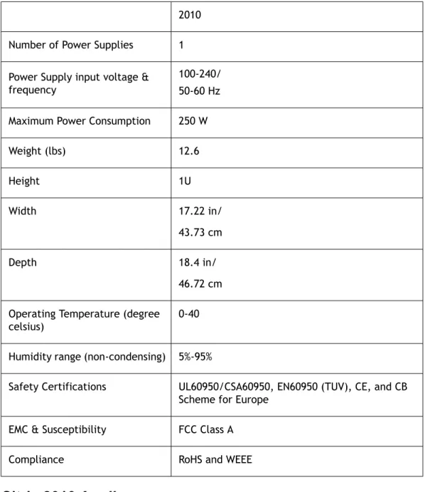
The following table summarizes the specifications of the Access Gateway Standard Edition hardware platform.
Table 2-1. Citrix Hardware Platform Summary 2010 Number of Power Supplies 1 Power Supply input voltage & frequency
100-240/ 50-60 Hz Maximum Power Consumption 250 W
Weight (lbs) 12.6 Height 1U Width 17.22 in/ 43.73 cm Depth 18.4 in/ 46.72 cm Operating Temperature (degree
celsius)
0-40
Humidity range (non-condensing) 5%-95%
Safety Certifications UL60950/CSA60950, EN60950 (TUV), CE, and CB Scheme for Europe
EMC & Susceptibility FCC Class A
Compliance RoHS and WEEE
Citrix 2010 Appliance
The Citrix 2010 appliance is a standard 1RU 19" rack-mountable appliance that supports up to 500 concurrent users.
w Two front-mounted 10/100/1000 Ethernet ports w One RS232 front-mounted serial console port w One rear-facing USB port
Access Gateway Enterprise Edition Hardware
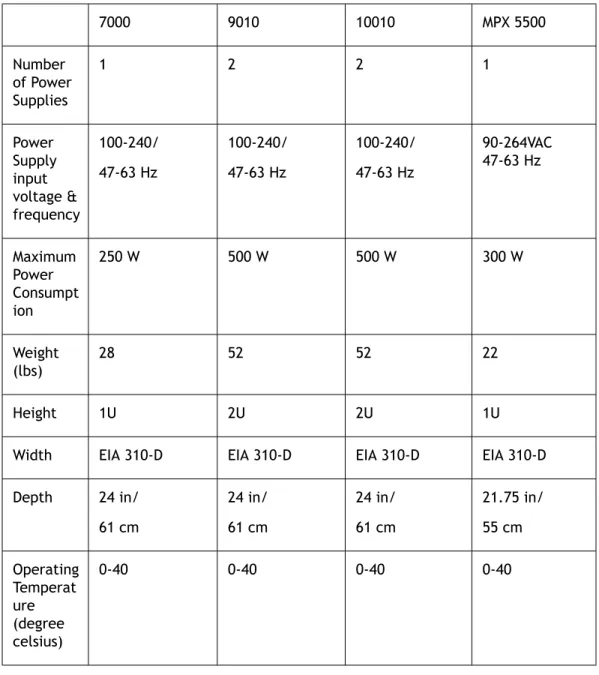
The following table summarizes the specifications of the Access Gateway Enterprise Edition hardware platforms.
Table 2-2. Citrix Hardware Platform Summary
7000 9010 10010 MPX 5500 Number of Power Supplies 1 2 2 1 Power Supply input voltage & frequency 100-240/ 47-63 Hz 100-240/ 47-63 Hz 100-240/ 47-63 Hz 90-264VAC 47-63 Hz Maximum Power Consumpt ion 250 W 500 W 500 W 300 W Weight (lbs) 28 52 52 22 Height 1U 2U 2U 1U
Width EIA 310-D EIA 310-D EIA 310-D EIA 310-D Depth 24 in/ 61 cm 24 in/ 61 cm 24 in/ 61 cm 21.75 in/ 55 cm Operating Temperat ure (degree celsius) 0-40 0-40 0-40 0-40
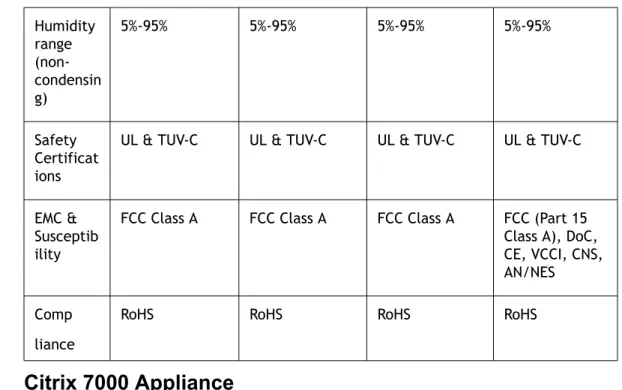
Humidity range (non-condensin g) 5%-95% 5%-95% 5%-95% 5%-95% Safety Certificat ions
UL & TUV-C UL & TUV-C UL & TUV-C UL & TUV-C
EMC & Susceptib ility
FCC Class A FCC Class A FCC Class A FCC (Part 15 Class A), DoC, CE, VCCI, CNS, AN/NES Comp
liance
RoHS RoHS RoHS RoHS
Citrix 7000 Appliance
The Citrix 7000 appliance is a single-core processor, 1U appliance that ships with 1 GB of memory. The appliance supports 2,500 concurrent users.
Note: The 9.1 nCore release is not supported on this appliance.
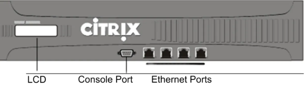
The following figure shows the front panel of the 7000.
Figure 2-1. Citrix 7000 Front Pane
The Model 7000 appliance has the following ports:
w Six 10/100 Base-T Ethernet network interfaces (or ports), named 1/1, 1/2, 1/3, 1/4, 1/5, and 1/6. Port 1/1 is the upper-left port, port 1/2 is the port beneath it, and the other 10/100BASE-T ports are named sequentially as you move from left to right, top to bottom.
w Two 10/100/1000 Base-T Ethernet network interfaces (or ports), named 1/7 and 1/8. Port 1/7 is the upper-right port, and port 1/8 is the port beneath it.
Note: The network port numbers on all appliances consist of two numbers
will always be either 0 or 1. The second number is the interface port number. Ports on appliances are numbered sequentially starting with 1.
w One RS232 serial console port.
The following figure shows the back panel of the 7000 appliance.
Figure 2-2. Citrix 7000 Back Panel
The following components are visible on the back panel of the 7000 appliance: w A removable hard disk drive that is used to store user data.
w An appliance reset switch, which signals the 7000 to perform an orderly shutdown after saving all data.
w A removable compact flash drive that is used to store the operating system. w A power switch, which turns off power to the 7000 just as if you were to unplug it. w A 250 watt, 110-220 volt power supply with fan.
Citrix 9010 Appliance
The Citrix 9010 appliance is a single-core processor, 2U appliance that ships with 2 GB of memory. The 9010 appliance is available in the following versions: the copper Ethernet version, the fiber SFP (Small Form Factor Pluggable) version, and the FIPS (Federal Information Processing Standards) version.
Note: The 9.1 nCore release is not supported on this appliance.
The following figure shows the front panel of the 9010 model with copper Ethernet ports.
The following figure shows the front panel of the 9010 with fiber SFP ports.
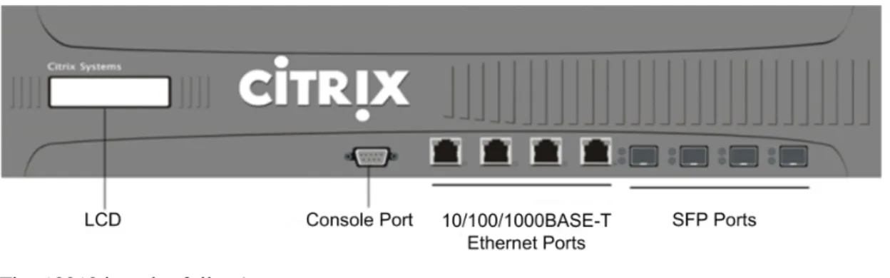
Figure 2-4. Citrix 9010 Front Panel with SFP Ports
The 9010 models have the following ports: w One RS232 serial console port.
w Network ports
• 9010, copper Ethernet model. Four copper Ethernet 10/100/1000BASE-T ports, numbered 1/1, 1/2, 1/3, and 1/4 from left to right.
• 9010, SFP model. Four SFP ports, numbered 1/1, 1/2, 1/3, and 1/4 from left to right.
When facing the bezel, the upper LEDs to the left of each optical SFP port inset represent connectivity. They are lit and amber in color when active. The lower LEDs represent throughput. They are lit and green when active.
• 9010 FIPS model. Same as the 9010, non-FIPS model.
Note: The network port numbers on all appliances consist of two numbers
separated by a forward slash. The first number is the port adapter slot number and will always be either 0 or 1. The second number is the interface port number. Ports on appliances are numbered sequentially starting with 1.
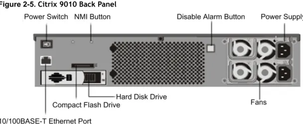
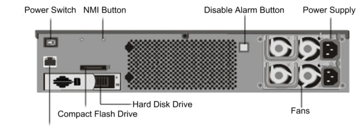
The following figure shows the back panel of the 9010 models.
Note: The back panels of the three 9010 models are the same.
The following components are visible on the back panel of the 9010 models:
w A power switch, which turns off power to the 9010, just as if you were to unplug both power supplies.
w One 10/100BASE-T copper Ethernet port, numbered 0/1. w A removable hard disk drive that is used to store user data.
w A non-maskable interrupt (NMI) button, which signals the 9010 to perform an orderly shutdown after saving all files. You must use a pen, pencil, or other pointed object to press this button, which is located inside a small hole to prevent it being pressed accidentally.
w A removable compact flash drive that is used to store the operating system. w A disable alarm button, which silences the alarm that the 9010 sounds when it is
receiving power from only one of its power supplies.
Press this button to prevent the power alarm from sounding when you have plugged the 9010 into only one power outlet or when one power supply is malfunctioning and you wish to continue operating the 9010 until it is repaired.
w Two 500 watt, 110-220 volt power supplies, each with two fans.
You plug separate power cords into the power supplies and connect them to separate wall sockets. The 9010 functions properly with a single power supply; the extra power supply serves as a backup.
Citrix 10010 Appliance
The Citrix 10010 appliance is a single-core processor, 2U appliance that ships with 4 GB of memory. The appliance supports 10,000 concurrent users. It has the same Ethernet network interfaces as the Model 9010 appliance.
You can use the serial port on each appliance to connect a computer directly to the appliance using a serial cable to access the appliance command-line interface.
Note: The 9.1 nCore release is not supported on this appliance.
The following figure shows the front panel of the 10010 appliance.
Figure 2-6. Citrix 10010 Front Panel
w One RS232 serial console port.
w Four copper Ethernet 10/100/1000BASE-T ports, numbered 1/5, 1/6, 1/7, and 1/8 from left to right.
w Four SFP (Small Form Factor Pluggable) ports, numbered 1/1, 1/2, 1/3, and 1/4 from left to right.
When facing the bezel, the upper LEDs to the left of each optical SFP port inset represent connectivity. They are lit and amber in color when active. The lower LEDs represent throughput. They are lit and green when active.
Note: The network port numbers on all appliances consist of two numbers
separated by a forward slash. The first number is the port adapter slot number and will always be either 0 or 1. The second number is the interface port number. Ports on appliances are numbered sequentially starting with 1.
The following figure shows the back panel of the 10010 appliance.
Figure 2-7. Citrix 10010 Back Panel
The following components are visible on the back panel of the 10010:
w A power switch, which turns off power to the 10010, just as if you were to unplug both power supplies.
w A non-maskable interrupt (NMI) button, which signals the 10010 to perform an orderly shutdown after saving all files. You must use a pen, pencil, or other pointed object to press this button, which is located inside a small hole to prevent it being pressed accidentally.
w A disable alarm button, which silences the alarm that the 10010 sounds when it is receiving power from only one of its power supplies.
Press this button to prevent the power alarm from sounding when you have plugged the 10010 into only one power outlet or when one power supply is malfunctioning and you wish to continue operating the 10010 until it is repaired.
You plug separate power cords into the power supplies and connect them to
separate wall sockets. The 10010 functions properly with a single power supply; the extra power supply serves as a backup.
w One 10/100BASE-T copper Ethernet port, numbered 0/1.
w A removable compact flash drive that is used to store the operating system. w A removable hard disk drive that is used to store user data.
Citrix MPX 5500 Appliance
The Citrix MPX 5500 is a single dual-core processor, 1U appliance that ships with 4 GB of memory. The appliance supports up to 5,000 concurrent users.
Note: The 9.1 nCore release is not supported on this appliance.
The following figure shows the front panel of the MPX 5500.
Figure 2-8. Citrix MPX 5500 Front Panel
Note: The LCD keypad is not functional in this release.
The MPX 5500 has the following ports: w One RS232 serial console port.
w Two 10/100/1000Base-T copper Ethernet ports, numbered 0/1 and 0/2 from left to right. You can use these ports to connect directly to the appliance for system administration functions.
w Four 10/100/1000Base-T copper Ethernet ports, numbered 1/1, 1/2, 1/3, and 1/4 from left to right.
Note: The network port numbers on all appliances consist of two numbers
separated by a forward slash. The first number is the port adapter slot number. The second number is the interface port number. Ports on appliances are numbered sequentially starting with 1.
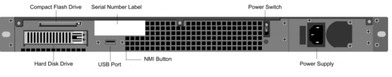
The following figure shows the back panel of the MPX 5500.
The following components are visible on the back panel of the MPX 5500:
w A 4 GB removable compact flash drive that is used to store the operating system. w A power switch that is a simple toggle switch that turns power to the MPX 5500 on
and off. While the power switch itself has O and I markings, the direction of the switch does not indicate the power state of the appliance.
w A removable hard disk drive that is used to store user data. w One USB port.
Note: The USB port is not functional in this release.
w A non-maskable interrupt (NMI) button, which signals the MPX 5500 to perform an orderly shutdown after saving all files. You must use a pen, pencil, or other pointed object to press this red button, which is located inside a small hole to prevent it being pressed accidentally.
w A single 300 watt, 110-220 volt power supply.
Common Enterprise Edition Hardware Components
Each platform has common front panel and back panel hardware components. The front panel has the LCD display and various ports. The back panel provides access to the power supply, fan, compact flash drive, and hard disk drive.
Front Panel Components
The front panel has an LCD display, an RS232 serial console port, copper Ethernet ports, and one gigabit copper and fiber SFP ports.
LCD Display
The LCD display on the front of every appliance platform displays messages about the current operating status of the appliance. These messages communicate whether your appliance has started properly and is operating normally. If the appliance is not operating normally, the LCD displays troubleshooting messages.
The LCD displays real-time statistics, diagnostic information, and active alerts. The dimensions of the LCD limit the display to two lines of 16 characters each causing the displayed information to flow through a sequence of screens. Each screen shows information about a specific function.
The LCD has a neon backlight. Normally, the backlight glows steadily. When there is an active alert, it blinks rapidly. If the alert information exceeds the LCD screen size, the backlight blinks at the beginning of each display screen. When the appliance shuts down, the backlight remains on for one minute, and then automatically turns off. There are nine types of special display screens on the LCD display. The first three screens in the list—the booting screen, the startup screen, and the out-of-service screen —are dispayed when your appliance is turning on, starting up, or out of service. The other screens are displayed when your appliance is in operation, and show
configuration information, alerts, HTTP information, network traffic information, CPU load information, and port information for your appliance.
w Booting Screen. The booting screen is displayed immediately after the appliance is turned on. The first line displays the hardware platform, as shown in the following figure.
Figure 2-10. LCD Booting Screen
The newer MPX platforms will display NSMPX-<platform number> in the first line. For example, the 5500 model will display NSMPX-5500.
w Startup Screen. The startup screen is displayed for a few seconds after the appliance successfully begins operation. The first line displays the hardware platform, the second line displays the software version and build number, as shown in the following figure.
Figure 2-11. LCD Startup Screen
w Out-of-Service Screen. The out-of-service screen is displayed when the appliance has undergone a controlled shudown, as shown in the following figure.
Figure 2-12. LCD Out-of-Service Screen
w Configuration Screen. The first line displays the status and time. STA indicates that the appliance is in standalone mode, PRI indicates that the appliance is a primary node in a high availability (HA) pair, and SEC indicates that the appliance is a secondary node in an HA pair. Appliance uptime is displayed in HH:MM format. The second line displays the IP address of the appliance, as shown in the following figure.
Figure 2-13. LCD Configuration Screen
w Alert Screen. The display changes depending on whether it is a known or an
unknown alert. The first line displays the status of the appliance as STA, PRI, or SEC. STA indicates that the appliance is in standalone mode, PRI indicates that the appliance is a primary node in a high availability (HA) pair, and SEC indicates that the appliance is a secondary node in an HA pair. The second line displays the appliance IP address, as shown in the following figures.
Figure 2-14. LCD Known Alert Screen
Figure 2-15. LCD Unknown Alert Screen
w HTTP Statistics Screen. The first line displays the rate of HTTP GETS per second. The second line displays the rate of HTTP POSTS per second, as shown in the following figure.
Figure 2-16. LCD HTTP Statistics Screen
w Network Traffic Statistics Screen. The first line displays the rate of data being received in megabits per second. The second line displays the rate of data being transmitted in megabits per second, as shown in the following figure.
Figure 2-17. LCD Network Traffic Statistics Screen
w CPU Load, Memory, and Connections Screen. The first line displays CPU utilization and memory utilization as a percentage. The second line displays the ratio of the number of server connections to the number of client connections.
Note: If the number of server or client connections exceeds 99,999, then the number will be displayed in thousands, with a suffix of K.
Figure 2-18. LCD CPU Load, Memory, and Connections Screen
w Port Information Screen. The S row ports display speed, flow control, and duplex information. The R row ports display the megabits per second received on the interface. The first port in both rows is the management port.
Figure 2-19. Port Information for an 8-port Appliance
Figure 2-20. Port Information for a 10-port Appliance
The following table defines the various abbreviations and symbols that display in the S row of the port information screen.
Table 2-3. Port Abbreviations and Symbols for S Row S Row Abbreviation/Symbol Description
Indicates a speed rate of 10 megabits per second, full duplex mode, and flow control OFF.
Indicates a speed rate of 100 megabits per second, full duplex mode, and flow control OFF.
Indicates a speed rate of 1 gigabit per second, full duplex mode, and flow control OFF.
Indicates a speed rate of 10 gigabits per second, full duplex mode, and flow control OFF.
Indicates a disconnected port.
Note: The R row does not display an abbreviation or symbol for a
disconnected port.
Indicates receive flow control regardless of speed rate or duplex mode.
Indicates transmit flow control regardless of speed rate or duplex mode.
Indicates receive and transmit flow control regardless of speed or duplex mode
Indicates a speed rate of 10 megabits per second, half duplex mode, and flow control OFF.
Indicates a speed rate of 100 megabits per second, half duplex mode, and flow control OFF.
Indicates a speed rate of 1 gigabit per second, half duplex mode, and flow control OFF
The following table defines the various abbreviations and symbols that display in the R row of the port information screen.
Table 2-4. Port Abbreviations and Symbols for R row R Row Abbreviation/Symbol Description
Indicates the port is disabled. Indicates receive speed is approximately 10% of line speed. Indicates receive speed is 50% of line speed.
Indicates receive speed is 75% of line speed.
Indicates receive speed is 100% of line speed.
Ports
The front panel contains several ports, including an RS232 serial console port, copper Ethernet ports, and copper and fiber SFP ports.
RS232 Serial Console Port
The RS232 serial console port on the front of each appliance provides a direct
connection between the appliance and a workstation or laptop, allowing direct access to the appliance for initial configuration or troubleshooting.
All hardware platforms ship with an appropriate serial cable used to connect your workstation or laptop computer to the appliance. For instructions on connecting your workstation or laptop to the appliance, see Installing Enterprise Edition Hardware on page 45.
Copper Ethernet Ports
The copper Ethernet ports installed on many models of the appliance are standard RJ45 ports.
There are two types of copper Ethernet ports that may be installed on your appliance: w 10/100BASE-T port. This type of port has a maximum transmission speed of 100
megabits per second (Mbps). The 7000 has six 10/100BASE-T ports installed on the front of the unit. All other models of the appliance have a single 10/100BASE-T port. w 10/100/1000BASE-T port. This type of port has a maximum transmission speed of 1
GB, ten times faster than the other type of copper Ethernet port. The 7000 has two 10/100/1000BASE-T ports. The 9010 copper Ethernet model and the 10010 each have four ports, and the MPX 5500 has six copper Ethernet ports.
To connect any of these ports to your network, you plug one end of a standard Ethernet cable into the port and plug the other end into the appropriate network connector.
One Gigabit (1000BASE-X) SFP Ports
The 1-Gigabit (1000BASE-X) SFP port is a high-speed port that can be converted to a copper Ethernet port using a Copper SFP transceiver or converted to a fiber optic port using the equivalent XFP transceiver. The 9010 SFP version and 10010 appliances each have four 1000BASE-X fiber ports.
Back Panel Components
The back panel has the power supply, fan, compact flash drive, and hard disk drive.
Power Supply and Fan
Appliances are configured with either a single power supply or, for higher capacity fault tolerant models, a dual-power supply configuration.
The power supplies on the 7000 and MPX 5500 appliances are configured with a single fan. The power supplies on the other appliance models are configured with two fans per power supply. Each unit ships with a standard power cord that plugs into the appliance’s power supply and an NEMA 5-15 plug on the other end for connecting to the power outlet on the rack or in the wall.
For specific information about the capacity of power supplies used on specific models and their power requirements, see the section describing that model later in this chapter.
Compact Flash Drive
The compact flash drive in all appliances contains the operating system for the unit. It is mounted as /flash.
Hard Disk Drive
The hard disk drive on all appliances contains logs and other data files. It is mounted as / var.
Cautions and Warnings
The installation instructions for the appliance provide instructions for carefully connecting the appliance to a power source. Heed all cautions and warnings regarding safety practices when working with power sources and supplies. To help ensure secure rack installation, sufficient airflow, and appliance stability, follow all prescribed precautions.
Important: Only trained and qualified personnel should install, maintain, or replace the appliance.
Power Supply Precautions
w Remove all jewelry and other metal objects that might come into contact with power sources or wires before installing or repairing the appliance. When you touch
both a live power source or wire and ground, any metal objects can heat up rapidly, and may cause burns, set clothing on fire, or fuse the metal object to an exposed terminal.
w Never stack the appliance on top of any other server or electronic equipment. w Do not block access to the power socket or power sockets where your appliance is
plugged in. In emergencies, unplugging the appliance is the fallback disconnection method.
w All appliances are designed to be installed on power systems that use TN earthing. Do not install your device on a power system that uses either TT or IT earthing. w Ensure that the appliance has a direct physical connection to the earth during
normal use. When installing or repairing a appliance, always ensure that the ground circuit is connected first, and disconnected last.
w Ensure that a fuse or circuit breaker no larger than 120 VAC, 15 A U.S. (240 VAC, 16 A international) is used on all current-carrying conductors on the power system to which your appliances are connected.
w Always unplug any appliance before performing repairs or upgrades.
w Do not overload the wiring in your server cabinet or on your server room rack. w During thunderstorms, or anticipated thunderstorms, located in the vicinity of the
building where your appliance is located, avoid performing any repairs or upgrades until the danger of lightning has passed.
w Never touch a power supply when the power cord is plugged in. As long as the power cord is plugged in, line voltages are present in the power supply even when the power switch is off.
w Ensure the stability of your appliance by installing it as follows:
• If the appliance is the only unit in the rack, mount it at the bottom of the rack. • When mounting the appliance in a partially filled rack, load the rack from the
bottom to the top with the heaviest server at the bottom of the rack. • If the rack has stabilizing devices available, install them before mounting or
servicing the appliance in the rack.
w When you dispose of an old appliance or any components, follow any local and national laws on disposal of electronic waste.
w To prevent possible explosions, replace expired batteries with the same model or a manufacturer-recommended substitute and follow the manufacturer’s instructions on battery replacement.
w Never remove a power supply cover or any sealed part that has the following label: Need to add screenshot/image: do-not-open_warning-message.wmf
Appliance Precautions
w Install the heaviest appliance on the bottom of the rack first, and then work up. Equipment should be mounted into a rack so that a hazardous condition does not arise due to uneven mechanical loading.
w Allow the power supply units and hot plug hard drives to cool before touching them. w To maintain proper cooling, always keep the rack's front door, panels, and appliance
components closed.
w Install the equipment near a socket outlet for easy access.
w If installed in a closed or multi-unit rack assembly, the ambient operating
temperature of the rack environment may be greater than the ambient temperature of the room. Therefore, consideration should be given to installing the equipment in an environment compatible with the manufacturer's maximum rated ambient temperature (Tmra).
Clearance Precautions
w Mount equipment into a rack with airflow sufficient for safe operation.
w Leave enough clearance in front of the rack to open the front door completely (25 inches).
w Leave approximately 30 inches of clearance behind the rack to allow for sufficient airflow and ease in servicing.
w This product is for installation only in Restricted Access Locations (RALs) such as dedicated equipment rooms and service closets.
Rack Precautions
w Ensure that the leveling jackets on the bottom of the rack are fully extended to the floor with the full weight of the rack resting on them.
w In a single rack installation, attach a stabilizer to the rack. w In multiple rack installations, couple (attach) the racks together.
w Always make sure the rack is stable before extending a component from the rack. w Extend only one component at a time, extending two or more simultaneously may
Installing Standard Edition Hardware
Topics:
• Preparing for Installation • Getting Ready to Install the
Access Gateway
• Selecting a Location for the Access Gateway
• Setting up the Access Gateway Hardware
• Installing the 2010 Appliance • Turning on the Appliance • Initial Configuration of the
Standard Edition Appliance
This chapter describes how to install the Citrix Access Gateway Standard Edition appliance. You start by unpacking the appliance and preparing the site and rack. After you determine that the location where you will install your appliance meets the environmental standards and the server rack is in place according to the instructions, you install the hardware. After you mount the appliance, you connect the cables, and turn on the appliance. Next, you perform initial configuration of the appliance. Be sure to observe the
Preparing for Installation
Before you install your new appliance, carefully unpack the appliance and make sure that all parts were delivered. Once you are satisfied that your appliance has been delivered to your expectations, verify that the location where the appliance will be installed meets temperature and power requirements and that the server cabinet or floor-to-ceiling cabinet is securely bolted to the floor and has sufficient airflow.
Only trained and qualified personnel should install, maintain, or replace the appliance and efforts should be taken to ensure that all cautions and warnings are followed.
Unpacking the Citrix Standard Edition Appliance
The hardware accessories for your particular appliance will include cables, adapters, and rail kit. Unpack the box that contains your new appliance on a sturdy table with plenty of space and inspect the contents.
Use the following list to verify that you received everything that should have been included in the box.
w The appliance you ordered. For a description of your appliance, see Introducing the Access Gateway Hardware on page 13.
w 1 power cable w 1 mounting rail kit
In addition to the items included in the box with your new appliance, you will need the following items to complete the installation and initial configuration process.
w Additional Ethernet cables for each additional Ethernet port that you will connect to your network.
w One available Ethernet port on your network switch or hub for each Ethernet port you want to connect to your network.
w A desktop or laptop/notebook computer to serve as a management workstation.
Preparing the Site and Rack
There are specific site and rack requirements for the appliance. You must make sure that adequate environmental control and power density are available. Racks must be bolted to the ground and have sufficient airflow. Preparing the site and rack are important steps in the installation process and will help ensure a smooth installation.
Site Requirements
The appliance should be installed in a server room or server cabinet with the following features:
w Environment control. An air conditioner, preferably a dedicated computer room air conditioner (CRAC), capable of maintaining the cabinet or server room at a
7000 ft, or 15 degrees C/60 degrees F at higher altitudes, a humidity level no greater than 45 percent, and a dust-free environment.
w Power density. Wiring capable of handling at least 4,000 watts per rack unit in addition to power needs for the CRAC.
Rack Requirements
The rack on which you install your appliance should meet the following criteria: w Rack characteristics. Racks should be either integrated into a purpose-designed
server cabinet or be the floor-to-ceiling type, bolted down at both top and bottom to ensure stability. If you have a cabinet, it should be installed perpendicular to a load-bearing wall for stability and sufficient airflow. If you have a server room, your racks should be installed in rows spaced at least 1 meter/3 feet apart for sufficient airflow. Your rack must allow your IT personnel unfettered access to the front and back of each server and to all power and network connections.
w Power connections. At minimum, two standard power outlets per unit. w Network connections. At minimum, four Ethernet connections per rack unit. w Space requirements. One empty rack unit for the 2010 appliance.
Getting Ready to Install the Access Gateway
To install the Access Gateway, verify that the contents of the box match the packing list. If an item on the packing list is missing from the box, contact Citrix Customer Care.
Materials and Information Needed for Installation
Before installing the Access Gateway, collect materials for the initial configuration and for the connection to your network.
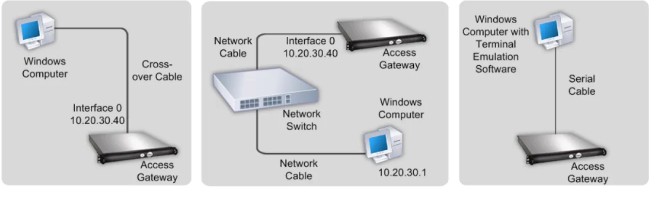
For initial configuration, use one of the following setups: w A cross-over cable and Windows computer
w Two network cables, a network switch, and a Windows computer w A serial cable and a computer with terminal emulation software For a connection to a local area network, use the following items:
w One network cable to connect the Access Gateway inside a firewall or to a server load balancer
w Two network cables to connect the Access Gateway located in the demilitarized zone (DMZ) to the Internet and secure network
Citrix recommends that you use the Access Gateway Standard Edition Pre-Installation Checklist to collect the following network information for appliances that are located in the secure network and in the DMZ:
w The Access Gateway internal IP address and subnet mask. w The Access Gateway external IP address and subnet mask.
w The Access Gateway fully qualified domain name (FQDN) for network address translation (NAT).
w The IP address of the default gateway device.
w The port to be used for connections. The default is 443.
If connecting the Access Gateway to a server load balancer, you need the following information:
w The Access Gateway IP address and subnet mask.
w The settings of the server load balancer as the default gateway device (if required). See the load balancer manufacturer’s documentation for more information.
w The fully qualified domain name (FQDN) of the server load balancer to be used as the external public address of the Access Gateway.
w The port to be used for connections. The default is 443.
Note: The Access Gateway requires the use of static IP addresses and does not support Dynamic Host Configuration Protocol (DHCP).
Selecting a Location for the Access Gateway
When selecting where to put the Access Gateway, consider the following:
w Leave enough clearance in front of the rack to enable you to open the front bezel completely
w Leave approximately 30 inches of clearance in the back of the rack to allow for sufficient airflow and easy servicing
w Install the Access Gateway in a restricted area, such as a dedicated lab or service closet
w Ground the rack to ensure that a reliable ground is maintained at all times
Setting up the Access Gateway Hardware
This section provides procedures for setting up the Access Gateway for the first time. For more information about the materials and equipment needed to set up the Access Gateway, see Getting Ready to Install the Access Gateway on page 35.
To physically connect the Access Gateway
1. Install the Access Gateway in a rack if it is rack-mounted.
For more information about installing the Access Gateway in a rack, see Installing the 2010 Appliance on page 37.
2. Connect the power cord to the AC power receptacle.
3. Connect either the serial cable to a Windows computer, a cross-over cable to a Windows computer, or an RJ-45 network cable to a network switch and the Access Gateway.
4. Configure the TCP/IP settings using the instructions in Initial Configuration of the Standard Edition Appliance on page 43.
Figure 3-1. Access Gateway connection options using a cross-over cable, a network switch, or terminal emulation
Installing the 2010 Appliance
This section discusses how to install the Access Gateway 2010 appliance in a rack. It includes:
w Identifying the Sections of the Rack Rails for the 2010 Appliance w Installing the 2010 Appliance in a Four-Post Rack
Identifying the sections of the rack rails for the 2010
appliance
The 2010 appliance is delivered with a set of inner rails in two sections: inner rails and inner rail extensions. The inner rails are attached to the appliance and do not interfere with normal use of the appliance if you choose not to install the appliance in a rack.
Figure 3-2. Access Gateway Model 2010 rails
To identify the sections of the rack rails for the 2010 appliance
Attach the inner rail extension to stabilize the appliance within the rack.
Installing the 2010 Appliance in a Four-Post Rack
The steps for installing the 2010 appliance in a four-post rack are: w Installing the inner rail extensions on the appliance
w Installing the outer rails to the rack w Installing the appliance in the rack
To install the inner rail extension
1. Place the inner rack extensions on the side of the appliance aligning the hooks of the appliance with the rail extension holes. Make sure the extension faces outward just like the preattached inner rail.
2. Slide the extension toward the front of the chassis. 3. Secure the chassis with the two screws.
Figure 3-3. Attaching the rail rack sections to the right side of the Access Gateway
When the rails are attached to the appliance, install the outer rails to the rack.
To install the outer rails to the rack
1. Attach the short bracket to the outside of the long bracket. The pins must be aligned with the slides. Both bracket ends must face the same direction. 2. Adjust both the short and long brackets to the correct distance so the rail fits
tightly into the rack.
3. Secure the long bracket to the front side of the outer rail with two M5 screws and the short bracket to the rear side of the outer rail with three M5 screws.
4. Repeat the above steps for the second rail.
Figure 3-5. Installing the outer rails to the server rack
When the rails are installed in the rack, you can install the Access Gateway.
To install the appliance in the rack
1. Confirm that the appliance includes the inner rails (A) and rail extensions (B). Confirm that the outer rails (C) are installed on the rack.
2. Line up the rails on the appliance (A and B) with the front of the rack rails (C). 3. Slide the appliance rails into the rack rails, keeping the pressure even on both
sides. You might have to depress the locking tabs during insertion.
When the appliance is pushed completely into the rack, you should hear the locking tabs click.
4. (Optional) Insert and tighten the thumbscrews that hold the front of the appliance to the rack.
Figure 3-6. Installing the Access Gateway into the rack
Installing the 2010 Appliance in a Two-Post Rack
If you are installing the appliance in a two-post (Telco) rack, follow the directions given on the previous pages for rack installation. The only difference in the installation procedure is the positioning of the rack brackets to the rack. Space them apart just enough to accommodate the width of the Telco rack, as illustrated below.
Figure 3-7. Installing the Access Gateway in a two-post (Telco) rack
Turning on the Appliance
After you have installed the appliance in a rack and connected the cables, you are ready to turn on the appliance.
Caution: You should remove all jewelry and other metal objects that might come into contact with power sources or wires before installing or repairing the appliance. When you touch both a live power source or wire and ground, any metal objects can heat up rapidly and may cause burns, set clothing on fire, or fuse the metal object to an exposed terminal.
To turn on the appliance
1. Verify that you are connected to the appliance through a console or Ethernet port. This will ensure that you can configure the appliance after it is turned on.
2. Plug in the power cable.
As it turns on, the appliance hums, and various lights on the surface flash. After a few seconds, the rapid changes in sound and lights gives way to a steady hum. 3. Verify that the LCD on the front panel is backlit.
Initial Configuration of the Standard Edition
Appliance
After you have installed your appliance in a rack, you are ready to perform the initial configuration. Once initial configuration is complete, you will need to refer to the administrator's guide for the feature you are installing.
Initial configuration can be performed by using a serial console.
Configuring TCP/IP Settings using the Serial Console
You can use the serial console to set the IP address and subnet of the network adapter that is called Interface 0, as well as the IP address of the default gateway device. All other configuration must be done using the Administration Tool. You can also use the serial console to test a connection with the ping command.
If you want to reach the Access Gateway through the serial console before making any configuration settings, use a serial cable to connect the Access Gateway to a computer that has terminal emulation software.
Note: Citrix recommends using both network adapters on the appliance. After
configuring the TCP/IP settings for Interface 0, use the Administration Tool to configure TCP/IP settings for Interface 1.
The serial console provides the following options for configuring the Access Gateway: w [0] Express Setup configures the TCP/IP settings for Interface 0 on the Access
Gateway Cluster > General Networking tab
w [1] Ping is used to ping other network devices to check for connectivity
w [2] Link Modes is used to set the duplex mode and speed mode for Interface 0 on the Access Gateway Cluster > General Networking tab
w [3] External Administration Port enables or disables connections to the Administration Tool from a remote computer
w [4] Display Log displays the Access Gateway log
w [5] Reset Certificate resets the certificate to the default certificate that comes with the Access Gateway
w [6] Change Administrative Password allows you to change the default administrator password of rootadmin
Important: Citrix recommends changing the administrator password before connecting the Access Gateway to your network. The new password can be six to 127 characters long and cannot begin or end with a space.
w [8] Log Out logs off of the Access Gateway
To configure initial TCP/IP settings using a serial cable
1. Connect the serial cable to the 9-pin serial port on the Access Gateway and connect the cable to a computer that is capable of running terminal emulation software.
2. On the computer, start a terminal emulation application such as HyperTerminal.
Note: HyperTerminal is not automatically installed on Windows 2000 Server, Windows Server 2003 or Windows Server 2008. To install HyperTerminal, use Add or Remove Programs in Control Panel.
3. Set the serial connection to 9600 bits per second, 8 data bits, no parity, 1 stop bit. Hardware flow control is optional.
4. Turn on the Access Gateway. The serial console appears on the computer terminal after about three minutes. If using HyperTerminal, press Enter.
5. On the serial console, enter the default administrator credentials. The user name is root and the password is rootadmin.
6. To set the IP address and subnet mask and the default gateway device for Interface 0, type 0 and press Enter to choose Express Setup. After you respond to the prompts, the information you entered appears. To commit your changes, type y; the Access Gateway restarts.
7. To verify that the Access Gateway can ping a connected network device, type 1
and enter the IP address of the device.
8. Remove the serial cable and connect the Access Gateway using either a cross-over cable to a Windows computer or a network cable to a network switch and then turn on the Access Gateway.
Installing Enterprise Edition Hardware
Topics:
• Preparing for Installation • Rack Mounting the Appliance • Installing and Removing the
SFP Transceivers • Connecting the Cables • Turning on the Appliance • Initial Configuration of the
Enterprise Edition Appliance
This chapter describes how to install the Citrix Access Gateway Enterprise Edition appliance. First you unpack the appliance and prepare the site and rack. After you determine that the location where you will install your appliance meets the environmental standards and the server rack is in place according to the instructions, you install the hardware. After you mount the appliance, you connect it to the network, to a power source, and to the console terminal that you will use for initial configuration. After you turn on the appliance, perform the initial configuration and assign management and network IP addresses. Be sure to observe the cautions and warnings listed with the installation instructions.
Preparing for Installation
Before you install your new appliance, carefully unpack the appliance and make sure that all parts were delivered. Once you are satisfied that your appliance has been delivered to your expectations, verify that the location where the appliance will be installed meets temperature and power requirements and that the server cabinet or floor-to-ceiling cabinet is securely bolted to the floor and has sufficient airflow.
Only trained and qualified personnel should install, maintain, or replace the appliance and efforts should be taken to ensure that all cautions and warnings are followed.
Unpacking the Citrix Enterprise Edition Appliance
The hardware accessories for your particular appliance, such as cables, adapters, and rail kit, will vary depending on the hardware platform you ordered. Unpack the box that contains your new appliance on a sturdy table with plenty of space and inspect the contents.
Use the following list to verify that you received everything that should have been included in the box.
The appliance you ordered. For a description and illustration of your particular unit, see Introducing the Access Gateway Hardware on page 13.
The following list specifies the number of 1-Gigabit SFPs included for each appliance model:
w 9010, fiber version: 4 SFPs w 10010: 4 SFPs
The following list specifies the number of power cables included for each appliance model:
w MPX 5500 and 7000: 1 power cable w 9010 and 10010: 2 power cables
Note: Ensure that a power outlet is available for each cable.
w 1 mounting rail kit with all the models.
In addition to the items included in the box with your new appliance, you will need the following items to complete the installation and initial configuration process.
w Additional Ethernet cables for each additional Ethernet port that you will connect to your network.
w One available Ethernet port on your network switch or hub for each Ethernet port you want to connect to your network.
Preparing the Site and Rack
There are specific site and rack requirements for the appliance. You must make sure that adequate environmental control and power density are available. Racks must be bolted to the ground and have sufficient airflow. Preparing the site and rack are important steps in the installation process and will help ensure a smooth installation.
Site Requirements
The appliance should be installed in a server room or server cabinet with the following features:
w Environment control. An air conditioner, preferably a dedicated computer room air conditioner (CRAC), capable of maintaining the cabinet or server room at a
temperature of no more than 21 degrees C/70 degrees F at altitudes up to 2100 m/ 7000 ft, or 15 degrees C/60 degrees F at higher altitudes, a humidity level no greater than 45 percent, and a dust-free environment.
w Power density. Wiring capable of handling at least 4,000 watts per rack unit in addition to power needs for the CRAC.
Rack Requirements
The rack on which you install your appliance should meet the following criteria: w Rack characteristics. Racks should be either integrated into a purpose-designed
server cabinet or be the floor-to-ceiling type, bolted down at both top and bottom to ensure stability. If you have a cabinet, it should be installed perpendicular to a load-bearing wall for stability and sufficient airflow. If you have a server room, your racks should be installed in rows spaced at least 1 meter/3 feet apart for sufficient airflow. Your rack must allow your IT personnel unfettered access to the front and back of each server and to all power and network connections.
w Power connections. At minimum, two standard power outlets per unit. w Network connections. At minimum, four Ethernet connections per rack unit. w Space requirements. One empty rack unit for the 7000 and MPX 5500 appliances,
and two consecutive empty rack units for all other appliances.
Rack Mounting the Appliance
Most appliances can be installed in standard server racks. The appliances ship with a set of rails, which you must install before you mount the appliance. The only tool you will need to install an appliance is a Phillips screwdriver.
Note: If you are installing the appliance as the only unit in the rack, mount it at the bottom. If the rack contains other units, make sure that the heaviest unit is at the bottom. If the rack has stabilizing devices available, install them before mounting the appliance.
The 7000 and MPX 5500 appliances each require one rack unit. The 9010 and 10010 appliances each require two rack units. Each of these units ships with a mounting rail
kit that contains two rail assemblies, one for the left side and the other for the right side of the appliance, and screws to attach the rails. You must install the assemblies before mounting the appliance in the rack.
Installing the Rails
An assembly consists of an inner rail and a rack rail. A locking tab on the inner rail prevents the appliance from coming out of the rack when the rail is fully extended for servicing.
To install the rails, you must first remove the inner rails from the rail assembly, attach the inner rails to the appliance, adjust the length of the rack rails, and then install the rack rails on the server cabinet or rack.
Perform the following tasks to install the rails: w Remove the inner rails from the rail assembly. w Attach the inner rails to the appliance. w Adjust the length of the rack rails.
w Install the rack rails on the server cabinet or rack.
To remove the inner rails from the rail assembly
1. Place the rail assembly on a flat surface.
2. Slide out the inner rail towards the front of the assembly.
3. Depress the locking tabs until the inner rail comes all the way out of the rail assembly as shown in the following figure.
Figure 4-1. Removing Inner Rails
4. Repeat steps 1 through 3 to remove the second inner rail.
To attach the inner rails to the appliance
1. Position the right inner rail behind the ear bracket on the right side of the appliance. 2. Align the holes on the rail with the corresponding holes on the side of the appliance.
3. Attach the rail to the appliance with screws as shown in the following figure.
Figure 4-2. Attaching Inner Rails
4. Repeat steps 1 through 3 to install the left inner rail on the left side of the appliance.
To adjust the length of the rail assembly
1. Measure the distance between the front and back posts of your rack.
2. Slide the extender so that the assembly, front end to back, fits the distance on the rack.
3. Carefully turn the assembly over and align a screw hole in the assembly with the appropriate slot in the extender.
4. Insert the screw on one side and attach a washer and nut to the screw end on the other side of the extender as shown in the following figure.
Figure 4-3. Adjusting Rail Length
5. Align a second screw hole in the assembly with the appropriate slot in the extender and repeat step 4.
6. Repeat steps 2 through 5 for the second rail assembly.
To install the rack rails
1. Position the rack rails at the desired location in the rack, keeping the sliding rail guide facing inward.
2. Insert two mounting screws into the ears in the front and back of the right rail and screw the assembly to the rack.
For non-threaded racks, it may be necessary to install cage-nuts for racks with square-holes or clip-nuts for racks with round holes.
Note: Make sure that both rack rails are at same height and that the rail guides are facing inward.
When you have finished, the rack rails should be installed in the rack as shown in the following figure.
Figure 4-4. Installing Rack Rails
Mounting the appliance
After you have installed the rails according to the instructions, mount the appliance securely in the rack.
Caution: If you are installing the appliance as the only unit in the rack, mount it at the bottom. If the rack contains other units, make sure that the heaviest unit is at the bottom. If the rack has stabilizing devices available, install them before mounting the appliance.
To install the appliance in the rack
1. Line up the inner rails attached to the appliance with the rack rails.
2. Slide the appliance into the rack rails, keeping the pressure even on both sides. You may need to depress the locking tabs when inserting the appliance. When the appliance is pushed completely into the rack, the locking tabs should snap into place. 3. Verify that the appliance is locked in place by pulling it all the way out from the
Figure 4-5. Rack Mounting the Appliance
Installing and Removing the SFP Transceivers
Note: This section applies to the 9010 and 10010 appliances.
A Small Form Factor Pluggable (SFP) is a compact optical transceiver offering speeds of up to 1 gigabit per second and is available in both copper and fiber types. A 10-Gigabit Small Form Factor Pluggable (XFP) is a compact optical transceiver offering speeds of up to 10 gigabits per second. Auto-negotiation is enabled by default on the 1000BASE-T and 1000BASE-X ports into which you insert your SFPs and XFPs. As soon as a link between the port and the network is established, the speed and mode are matched on both ends of the cable.
Only SFP and XFP transceivers provided by Citrix Systems are supported on appliances. Attempting to install third-party SFP or XFP transceivers on your appliance voids the warranty.
Insert transceivers into the slots provided at the front panel of the appliance. Both SFPs and XFPs can be inserted and removed even when the appliance is running. However, if you must remove a transceiver, be sure to folllow the correct procedure.
Caution: Do not install the transceiver with the cables attached as this can potentially damage the cable, connector, or the optical interface of the transceiver. Disconnect the cable before installing the transceiver.
Installing an SFP Transceiver
Only the 9010 and 10010 appliances include copper and fiber SFP transceivers. The MPX 5500 appliance does not have SFP transceivers.