PRACTICAL ADVANTAGES OF USING THE MECHANICS OF
CONTINUUM TO ANALYSE DEFORMATIONS OBTAINED FROM
GEODETIC SURVEY
Milan TALICH11 Research Institute of Geodesy, Topography and Cartography, Zdiby 98, CZ-250 66,
Czech Republic
Abstract: The paper demonstrates why applying of the theory of continuum is useful to deformation analyses obtained from repeated positional survey in geodesy. The mechanics of continuum may be applied as basis of communication during the multidisciplinar approach to geodetic and geotechnic monitoring. It serves also as a technological and scientific communication basis between geodesists and specialists of other professions as geotechnics, geophysics, building engineers etc. The independency of resulting deformation parameters to applied coordinate frame is shown, too. It is not necessary to try to find any conditions of placing the survey network in the coordinate system but the calculation should be adjusted as free network. Then errors originated from erroneous pre-requisites about stability of some selected points that are taken during normal calculation as stable (in the stable part of such location) will be completely eliminated. When compared to the sole listening of displacements this procedure enables to present deformation parameters in much more objective way and serves as a tool to demonstrate the relatively geodynamical trends of the territory in question.
1. INTRODUCTION
More and more results of geodetic activity are used in other disciplines. Such cases are, e.g., geodynamic research, where geodesy offers objective and relatively sufficiently exact information about motions and shape and dimension changes of the terrestrial surface or building constructions, generally speaking of some monitored object or locality. Such information is used to further studies, physical interpretations and determining causative factors. That means there is a multidisciplinary lead approach to solving such problems. Such approach requires creating of technological and scientific base for communication between specialists of different professions that will be suitable to all of them. In (Szostak-Chrzanovski et al. 2006) is proposed the mechanic of continuum to this purpose as support of deformation monitoring, their analysis and interpretation. Let us show other reasons and benefits leading to applying this theory in geodetic praxis.
Homogeneous territory or object in question is the required condition, of course. It means that if such condition is not fulfilled, then only division of the whole territory to several
homogeneous parts must be tried and calculations has to be done for each one of them separately.
Analysis of deformations of the terrestrial surface or of building constructions does not belong to problems that many geodesists solve in their everyday praxis. The main goal of deformation analysis is determination of deformation mechanism if we look at the object as at the mechanical system under deformations according the laws of mechanics of continuum. After such geometric analysis physical interpretation of results may follow.
Geometrical analysis, describes the change in shape and dimensions of the monitored object, as well as its rigid body movements (translations and rotations). The goal of the geometrical analysis is to determine in the whole deformable object the displacement and strain fields in the space and time domains.
Physical interpretation is based on the relationship between the causative factors (loads) and deformations.
Geodetic monitoring of deformations should follow in two steps. The first one is determination of displacements of selected points on the object in question (standard task). After it determination of displacement field in continuous form by their interpolation (generalized task) can follow. The second step is determination of deformations parameters by geometric analysis of continuum mechanics (strain analysis). Determination of displacements in the first step is usually done by repeated observation of geodetic network. But realisation of the second step is not so much usual among geodesists. Nevertheless strain analysis offers many conveniences.
2. GEOMETRIC ANALYSIS OF DEFORMATIONS BY CONTINUUM MECHANICS As it was told earlier, the principle of geodetic methods applications is based on repeated measurement and comparison of results of individual stages of measurements. Obtained differences in positions of points represent their displacements. The vector of point displacement is
di = (u1, u2, u3)iT = xio - xit
Where xio (resp. xit) is the vector of Pi point coordinates of fundamental (resp. actual in t-time) stage. This vector may be expressed as a function of coordinates:
u = (u1, u2, u3)T = u(x) = (u1(x), u2(x), u3(x))T = d , x = (x, y, z)T
( )
i i i z u y u x u z u y u x u z u y u x u i ⎟ ⎟ ⎟ ⎟ ⎟ ⎟ ⎟ ⎠ ⎞ ⎜ ⎜ ⎜ ⎜ ⎜ ⎜ ⎜ ⎝ ⎛ ∂ ∂ ∂ ∂ ∂ ∂ ∂ ∂ ∂ ∂ ∂ ∂ ∂ ∂ ∂ ∂ ∂ ∂ = = ⎟ ⎟ ⎟ ⎠ ⎞ ⎜ ⎜ ⎜ ⎝ ⎛ = 3 3 3 2 2 2 1 1 1 33 32 31 23 22 21 13 12 11 gradd E ε ε ε ε ε ε ε ε εIn the displacement field is valid next relation, see (Welsch 1983): di = Ei xi + t
where di is the displacement vector, Ei is the displacement gradient, xi is the coordinate vector,
t is the vector of translation elements. The strain tensor may be divided into two parts:
Ei = ei + Ωi = (ejl)i + ( ωjl)i j,l = 1,2,3
where: ei is the symmetric tensor of deformation, Ωi is the antisymmetric tensor of rotation, ejl = (εjl + εlj) / 2 , ωjl = (εjl – εlj) / 2 .
(
)
(
)
(
)
(
)
(
)
(
)
i i e e e e e e e e e i ⎟ ⎟ ⎟ ⎟ ⎟ ⎟ ⎠ ⎞ ⎜ ⎜ ⎜ ⎜ ⎜ ⎜ ⎝ ⎛ + + + + + + = ⎟ ⎟ ⎟ ⎠ ⎞ ⎜ ⎜ ⎜ ⎝ ⎛ = 33 32 23 31 13 32 23 22 21 12 31 13 21 12 11 33 23 13 23 22 12 13 12 11 2 1 2 1 2 1 2 1 2 1 2 1 ε ε ε ε ε ε ε ε ε ε ε ε ε ε ε e(
)
(
)
(
)
(
)
(
)
(
)
i i i ⎟ ⎟ ⎟ ⎟ ⎟ ⎟ ⎠ ⎞ ⎜ ⎜ ⎜ ⎜ ⎜ ⎜ ⎝ ⎛ − − − − − − − − − = ⎟ ⎟ ⎟ ⎠ ⎞ ⎜ ⎜ ⎜ ⎝ ⎛ − − − = 0 2 1 2 1 2 1 0 2 1 2 1 2 1 0 0 0 0 32 23 31 13 32 23 21 12 31 13 21 12 23 13 23 12 13 12 ε ε ε ε ε ε ε ε ε ε ε ε ω ω ω ω ω ω Ω It could be written: di = ( ei + Ωi ) xi + tWe could determine the deformation parameters from ei and Ωi . This may be dome as a 3D solution as well as in plane. Such plane could be e.g., parallel with XY or XZ or YZ or in a more general way any plane of the local coordinate system to which space displacements will be projected.
It holds e.g., for displacements projected to XY of the local coordinate system:
22 11 e e + = Δ - total dilatation 22 11 1 =e −e γ - shear strains 12 2 =2e γ - shear strains 2 2 2 1 γ γ γ = + - total shear
(
γ)
ε = Δ+ 2 11 - axis of maximum strain
(
γ)
ε = Δ−
2 1
2 - axis of minimum strain
⎟⎟ ⎠ ⎞ ⎜⎜ ⎝ ⎛ = 1 2 arctg 2 1 γ γ
ϕ - direction of axis of maximum strain
π ϕ ψ 4 1 +
= for ω12 >0 - direction of shear strain π ϕ ψ 4 1 −
= for ω12 <0 - direction of shear strain
Theoretical solution and derivation of these formulas in question may be found in many publications — e.g., (Szostak-Chrzanovski 2006), (Altiner 1999), (Talich 1994) and (Talich, Kostelecký, Vyskočil 1993).
3. DEFORMATION PARAMETERS CHARACTERS AND BENEFITS RESULTING FROM THEM
It is worth noting that all displacements depend on selected coordinate frame. On contrary, all deformation parameters of last equations except the ψ and φ directions are on used coordinate frame independent, and insensitive to translation and rotation. And this is the reason why deformation parameters and their applications are important in practice.
In the case of point displacements calculation the resulting character of displacements is quite unambiguously given by the applied coordinate frame or by conditions of geodetic network placing in the coordinate frame.
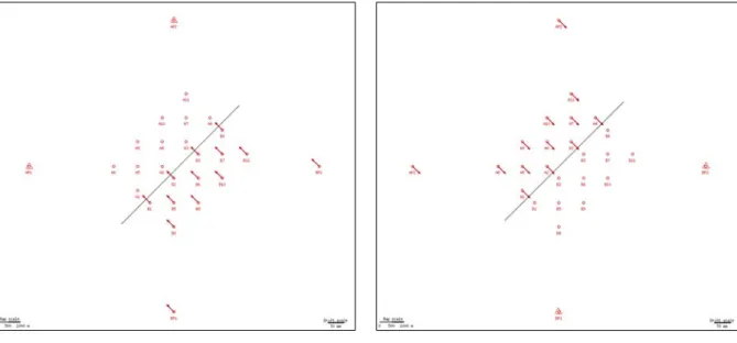
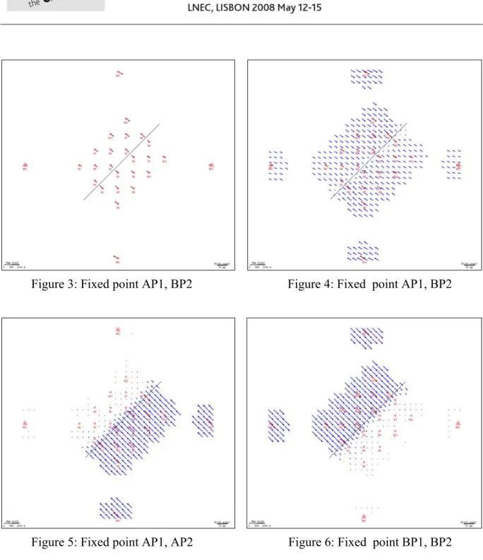
The first condition that has to be fulfilled is net adjustment as free network to prevent its scale changes or even its deforming. Usually selected points that are expected to be in the stable part of location are chosen like fixed. More exactly said: in the case of free networks, these points are chosen like points included at the condition of being placed in the coordinate frame (e.g. by selecting among identical points during the Helmert transformation). Selecting of such points is usually based on expected physical properties of the locality. Nevertheless we are never quite sure that our expectations about points stability are good and well fulfilled. The situation may be shown on models. Let us expect a fault in the locality in question and moving of two quite rigid plates again each other (this may happen e.g. by plunging of one plate under the second plate). The following pictures 1 to 3 show such model situation. There are three different ways of fixed point chosen leading to quite different character of calculated displacements of determined points of the same network. Points that are selected as fixed points and that are supposed to be in the stable part of location, are always marked by red triangle. To accentuate character of determined displacements there are on following pictures 4 to 6 also interpolated displacements fields represented. As seen from pictures, following physical interpretation of such calculated displacements could lead to quite erroneous or contradictory results. And this all is nothing else than influence of calculation and data selecting.
Figure 3: Fixed point AP1, BP2 Figure 4: Fixed point AP1, BP2
Figure 5: Fixed point AP1, AP2 Figure 6: Fixed point BP1, BP2 At this moment it will be quite convenient to go to the second step, determination of de-formation parameters according the mechanics of continuum. With regard to their independency to the selected coordinate frame and insensitivity to translation or rotation we will obtain from all possible variants of displacements calculation always the same deformation values. It means that it is not necessary to deal with conditions of placing the geodetic network in the coordinate frame (fixed points declaration). In other words, which points should be declared as fixed or not. The only remaining thing is calculation of network adjustment as free network, i.e. to choose only necessary number of conditions to their
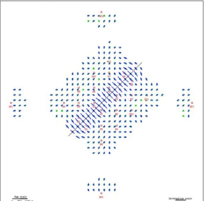
length) three and in the case of horizontal network without given dimension four. Different condition selections do not mean anything else in the case of free network than application of rotation and translation and calculation of deformations does not depend on it, as was already said. The above mentioned is given on fig. 7 which is common to all variants of calculated displacements.
Figure 7: Deformations parameters are the same for all variants of fixed points
This means in practice that errors from bad (erroneous) expectations about stability of some selected points, that we consider at common calculations of displacements from repeated measurement as stable (in the stable part of locality), are totally eliminated.
As such a mistake we could consider for instance GPS antenna exchange (change of phase centre of a new antenna against the old one) of a permanent station at access point of the GPS net. Even this mistake will be during calculation of deformation parameters totally eliminated provided that it leads to the shift of whole network and this point is not included into calculation of the field of displacements and deformation.
The other advantage is the fact that it is not necessary (regarding calculation of deformation parameters) to discuss the problem of transforming displacements given e.g. in coordinates frame ITRF into ETRF, or to reduce displacements in ITRF by movements of tectonic plate according to some of geodynamic models as e.g. APKIM2000 (Drewes and Angermann 2001) or NNR-NUVEL (Shuanggen and Wenyao 2004).
In our model case it is possible to deduce the real geodynamic activities based on given de-formation parameters. Above all, the real situation is disclosed, i.e. movement of two
relatively consistent plates one against the other with unambiguously defined process of disruption in the territory, as described in figure 7.
That means that, contrasting to displacements, deformations represent objective tool for disclosure of real relative geodynamic trends in the researched territory.
4. PRACTICAL EXAMPLE
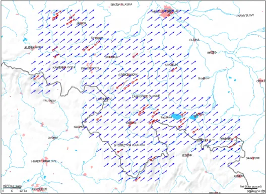
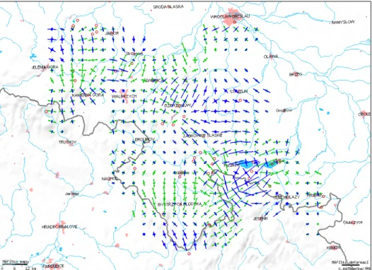
Deformation network GEOSUD in the area of Polish Sudetes and the Fore-Sudetic Block discussed in (Cacon et al. 2005) is chosen as a practical example. It is geodynamic network of repeated GPS measurements. Deformation parameters calculations are made by support of web application (Talich and Havrlant 2008) accessible at http://www.vugtk.cz/~deformace/ . In figure 8, resulting displacements are stated in coordinate frame ITRF 2000. In figure 9 “residual” displacements after their reduction using model APKIM2000 are displayed. All displacements in ITRF are approximately of the same size, 24 to 27 mm /year, and approximately of the same direction. On the other hand, “residual” displacements after reduction to local system are of different character with size from 0,3 to 3,7 mm / year and different directions. These trends are further emphasized by displacements field, where displacements on measured points are displayed in red colour and displacements stated by their interpolation in grid in blue colour.
Figure 8: GEOSUD network, displacement field in ITRF 2000
However, both displacements values lead to the same field of deformation displayed in picture 10. The independence of deformation parameters on translations and rotations was thus proved by practical calculation, in this case represented by reduction in accordance with model APKIM2000. In other words, displacements reduction from ITRF2000 into local
Figure 9: GEOSUD network, displacement field in “local” system
5. CONCLUSION
The aim of this article was to show the practical advantage of the usage of theory of mechanics of continuum for disclosure of real relative geodynamic effects in researched territories, eventually of dynamics researched entities or construction structures. Mechanics of continuum give results, that are better understandable even for experts from different fields than geodesy. Therefore it can serve as technological and scientific basis for communication among experts from different professional fields. Besides that, its usage also eliminates some impacts of measurement and calculations during geodetic networks processing, which enables access to more credible and objective results, especially in comparison with pure displacements determination of points in the monitored object.
References
Altiner, Y. (1999). Analytical Surface Deformation Theory for Detection of the Earth's Crust Movements. Springer-Verlag Berlin, Heidelberg, New York. 1999, X, 100 pp. 20 figs., ISBN: 3-540-65820-3
Cacon, S., Vyskočil, P., Talich, M., Kontny, B., Bosy, J. (2005). Deformations analysis of the Polish Sudetes and Fore-Sudetic block. Reports on geodesy, Institute of Geodesy and Geodetic Astronomy of the Warsaw University of Technology, No. 2 (73), 2005, Warsaw, p. 211 – 219, 5 obr., tab.
Drewes H. and Angermann D. (2001). The actual plate kinematic and crustal deformation model 2000 (APKIM 2000) as a geodetic reference system. In: IAG 2001 Scientific
Assembly, Budapest, Hungary, 5-6 September, 2001, (Poster),
http://www.dgfi.badw.de/fileadmin/DOC/2001/DS_APKIM.pdf
Kostelecký, J., Talich, M. and Vyskočil, P. (1994). Crustal Deformation Analysis in the International Center on Recent Crustal Movements. Journal of the Geodetic Society of Japan - 40/4 (1994), p. 301-308.
Shuanggen J. and Wenyao Z. (2004). A revision of the parameters of the NNR-NUVEL-1A plate velocity model. Journal of Geodynamics, 38, 1, 2004, p. 85-92.
http://www.sciencedirect.com/science/article/B6V9X-4CJ45VD-1/2/2a74fcf2685d080efe4677ac7a0785df
Szostak – Chrzanowski, A., Prószyñski, W. and Gambin, W. (2006). Continuum Mechanics as a Support for Deformation Monitoring, Analysis, and Intrpretation, In: Kahmen, H. and Chrzanowski, A. (Eds.), Proceedings 3rd IAG / 12th FIG Symposium, Baden, May 22-24, 2006, Baden, ISBN: 3-9501492-3-6.
Talich, M., Kostelecký, J. and Vyskočil, P. (1993). Modelling of Horizontal Movements and Computing Method of Deformation Fields at the International Center On Recent Crustal Movements. In: Zpráva o řešení vědeckého projektu 4-01-60 Geodézie a dynamika
Země v roce 1993 (Report about solution of research project 4-01-60 Geodesy and
dynamic of the Earth in 1993), VÚGTK, 1993, p.104-115.
Talich, M. (2007). Analýza deformací v poddolovaných lokalitách z opakovaných polohových měření s využitím webové aplikace a mapových služeb WMS. Acta Montanistica Slovaca, 12 (2007), mimoriadne číslo 3, p. 567-575, ISSN 1335-1788. http://actamont.tuke.sk/pdf/2007/s3/41Talich.pdf
Talich, M. and Havrlant, J. (2008). Application of deformation analysis and its new possibilities. In: 13th FIG Symposium on Deformation Measurements and Analysis (WG 6.1) with the 4th IAG Symposium on Geodesy for Geotechnical and Structural Engineering (SC 4.2) - Measuring the Changes, Lisbon, Portugal, 12-15 May, 2008, (in print).
Welsch, W. M. (1983). Finite elements analysis of strain patterns from geodetic observations across a plate margin. Tectonophysics, 97, pp.57-71. Elsevier. Amsterdam 1983
Corresponding author contacts Milan TALICH
Research Institute of Geodesy, Topography and Cartography Ustecka 98, CZ 250 66, Zdiby