NAVAL
POSTGRADUATE
SCHOOL
MONTEREY, CALIFORNIA
MBA PROFESSIONAL REPORT
Best Value Analysis of Tool/Individual Material Readiness
List (IMRL) Items for Carrier Air Wing Five (CVW-5)
F/A-18 Hornet Squadrons from NAF Atsugi
to MCAS Iwakuni, Japan
By:
Jose A. Martinez
Gavin
D.
Guidry
June 2012
Advisors: Geraldo Ferrer, Keebom Kang
REPORT DOCUMENTATION PAGE Form Approved OMB No. 0704-0188 Public reporting burden for this collection of information is estimated to average 1 hour per response, including the time for reviewing instruction, searching existing data sources, gathering and maintaining the data needed, and completing and reviewing the collection of information. Send comments regarding this burden estimate or any other aspect of this collection of information, including suggestions for reducing this burden, to Washington headquarters Services, Directorate for Information Operations and Reports, 1215 Jefferson Davis Highway, Suite 1204, Arlington, VA 22202-4302, and to the Office of Management and Budget, Paperwork Reduction Project (0704-0188) Washington DC 20503.
1. AGENCY USE ONLY (Leave blank) 2. REPORT DATE
June 2012
3. REPORT TYPE AND DATES COVERED
MBA Professional Report
4. TITLE AND SUBTITLE Best Value Analysis of Tool/Individual Material
Readiness List (IMRL) Items for Carrier Air Wing Five (CVW-5) F/A-18 Hornet Squadrons from NAF Atsugi to MCAS Iwakuni, Japan
5. FUNDING NUMBERS
6. AUTHOR(S) Jose A. Martinez, Gavin D. Guidry
7. PERFORMING ORGANIZATION NAME(S) AND ADDRESS(ES)
Naval Postgraduate School Monterey, CA 93943-5000
8. PERFORMING ORGANIZATION
REPORT NUMBER
9. SPONSORING /MONITORING AGENCY NAME(S) AND ADDRESS(ES)
N/A
10. SPONSORING/MONITORING AGENCY REPORT NUMBER
11. SUPPLEMENTARY NOTES The views expressed in this thesis are those of the author and do not reflect the official policy
or position of the Department of Defense or the U.S. Government. IRB Protocol number ______N/A________.
12a. DISTRIBUTION / AVAILABILITY STATEMENT
Approved for public release; distribution is unlimited
12b. DISTRIBUTION CODE 13. ABSTRACT (maximum 200 words)
In 2005, a U.S.-Japan Security Consultative Committee agreed to shift the Carrier Air Wing Five (CVW-5) homeport from Atsugi Naval Air Station (NAS), Japan, to Marine Corps Air Station Iwakuni (MCASI), Japan, in 2016. Currently the 35 mile distance between Atsugi, where the air wing is based and Yokosuka, where the carrier is docked, does not constitute a significant burden to the supply chain. However, when CVW-5 F/A-18 Hornets are repositioned to MCAS Iwakuni, it will significantly impact transportation costs due to the additional 542-mile distance to move Tool/IMRL assets to the carrier for air wing embarkation. In the same timeframe of the air wing home port transition, the composition of the air wing will be evolving to become the Navy’s first unit comprised of all Hornet variant aircraft. This analysis tries to determine the cost savings that may be involved with consolidation of Tool/IMRL outfitting allowances. Additionally, the analysis shows that MCAS Iwakuni may bring further asset exploitation opportunities due to the Marine Hornet squadrons already based there, whereas Atsugi has no Hornet presence other than CVW-5.
14. SUBJECT TERMS: Tools, IMRL, CVW-5, CVN-73, CFAY, NAF Atsugi, MCAS Iwakuni 15. NUMBER OF
PAGES 97 16. PRICE CODE 17. SECURITY CLASSIFICATION OF REPORT Unclassified 18. SECURITY CLASSIFICATION OF THIS PAGE Unclassified 19. SECURITY CLASSIFICATION OF ABSTRACT Unclassified 20. LIMITATION OF ABSTRACT UU
NSN 7540-01-280-5500 Standard Form 298 (Rev. 2-89)
Approved for public release; distribution is unlimited
BEST VALUE ANALYSIS OF TOOL/INDIVIDUAL MATERIAL READINESS LIST (IMRL) ITEMS FOR CARRIER AIR WING FIVE
(CVW-5) F/A-18 HORNET SQUADRONS FROM NAF ATSUGI TO MCAS IWAKUNI, JAPAN
Jose A. Martinez, Lieutenant Commander, United States Navy Gavin D. Guidry, Lieutenant, United States Navy
Submitted in partial fulfillment of the requirements for the degree of
MASTER OF BUSINESS ADMINISTRATION from the
NAVAL POSTGRADUATE SCHOOL June 2012 Authors: _____________________________________ Jose A. Martinez _____________________________________ Gavin D. Guidry Approved by: _____________________________________ Dr. Geraldo Ferrer Lead Advisor _____________________________________ Dr. Keebom Kang Support Advisor _____________________________________
William R. Gates, Dean
BEST VALUE ANALYSIS OF TOOL/INDIVIDUAL MATERIAL
READINESS LIST (IMRL) ITEMS FOR CARRIER AIR WING FIVE
(CVW-5) F/A-18 HORNET SQUADRONS FROM NAF ATSUGI TO
MCAS IWAKUNI, JAPAN
ABSTRACT
In 2005, a U.S.-Japan Security Consultative Committee agreed to shift the Carrier Air Wing Five (CVW-5) homeport from Atsugi Naval Air Station (NAS), Japan, to Marine Corps Air Station Iwakuni (MCASI), Japan, in 2016. Currently the 35 mile distance between Atsugi, where the air wing is based and Yokosuka, where the carrier is docked, does not constitute a significant burden to the supply chain. However, when CVW-5 F/A-18 Hornets are repositioned to MCAS Iwakuni, it will significantly impact transportation costs due to the additional 542-mile distance to move Tool/IMRL assets to the carrier for air wing embarkation. In the same timeframe of the air wing home port transition, the composition of the air wing will be evolving to become the Navy’s first unit comprised of all Hornet variant aircraft. This analysis tries to determine the cost savings that may be involved with consolidation of Tool/IMRL outfitting allowances. Additionally, the analysis shows that MCAS Iwakuni may bring further asset exploitation opportunities due to the Marine Hornet squadrons already based there, whereas Atsugi has no Hornet presence other than CVW-5.
TABLE OF CONTENTS
I. INTRODUCTION...1
A. BACKGROUND ...1
1. Current Operational Picture ...3
a. United States Navy 7th Fleet ...4
b. NAF Atsugi ...5
c. Fleet Activities Yokosuka ...6
d. USS George Washington (CVN 73): Forward Deployed Carrier ...7
e. Carrier Air Wing Five ...8
f. Marine Corps Air Station Iwakuni ...9
g. Maintenance Labor ...12
2. Pending Operational Picture ...12
3. About This Thesis ...13
II. TOOL/INDIVIDUAL MATERIAL READINESS LIST PRACTICES ...15
A. INDIVIDUAL MATERIAL READINESS LIST ...15
1. Governing References ...15 2. Coding of Assets ...16 a. Code P ...16 b. Code D ...16 c. Code E ...17 d. Code M...17 e. Code N ...17 f. Code L ...17 3. Responsible Levels ...17
a. Aviation Support Equipment Program Manager ...17
b. Support Equipment Controlling Authority ...18
c. Area Commander ...18 d. Activity Level ...18 4. Outfitting ...19 a. Methods ...20 b. Occasion ...20 5. Tracking Databases ...21
a. Support Equipment Resource Management Information System ...21
b. Local Asset Management System ...21
6. Transfer Procedure ...22
7. Accountability Requirement ...22
a. Annual Inventory ...23
b. Maintenance Officer Relief Inventory ...23
c. Work Center Quarterly Inventory ...23
1. Governing References ...24
a. Naval Aviation Maintenance Program ...24
b. Tool Control Program ...25
2. Compliance with these Tool Control Manuals ...26
3. Responsibilities: O-Level, I-Level, and COMFRC Activities ...26
a. Aircraft Controlling Custodians ...26
b. The Maintenance Officer/Fleet Readiness Center Equivalent...27
c. The Assistant Maintenance Officer/Industrial Training Department ...27
d. The Maintenance Material Control Officer /Production Control Officer ...27
e. The Program Manager/Coordinator ...27
4. TCP Implementation ...28
5. Tool Containers ...28
6. Proposed Changes, Deviations, and Additions ...29
7. Foreign Object Damage ...29
III. METHODOLOGY AND REFERENCE DATA ...31
A. DATA SOURCES ...31 1. Brian Kudrna ...31 2. Raymond D. Wendrzycki ...31 3. David A. Dougherty ...32 4. CVW-5 Maintenance Officer ...32 5. CNAF Publications ...32 6. Type/Model/Series Publications ...32
7. NAF Atsugi to MCAS Iwakuni Transition Planning Documents ...32
B. ANALYSIS TECHNIQUES ...32
1. Valuation of Duplicated Assets ...34
a. Monetary Criteria ...34 b. Ease of Use ...34 c. Spare Parts ...35 d. Enhanced Readiness ...36 e. Prevention of Damage ...37 f. Morale...38
2. Upkeep/Preservation Personnel for Unused Assets ...39
3. Cost Benefit Analysis ...40
4. Risk Analysis ...40
C. ASSUMPTIONS ...40
1. Frequency of Carrier Deployments ...40
2. Carrier Location ...41
3. Air Wing Location ...42
4. Air Wing Composition ...42
5 Transport Medium...43
IV. QUANTITATIVE ANALYSIS ...45
A. THE RISK OF TRANSPORTATION ...45
1. Objective ...45
2. Assumptions ...46
a. Tools and Individual Material Readiness List ...46
b. Damage During Transport ...46
c. Traffic Accident Rate ...47
3. Methodology ...47
4. Building the Model ...47
5. Accident Rates ...48
6. Interpretation ...49
B. LIFE-CYCLE COST ANALYSIS ...51
1. Objective ...51
2. Assumptions ...52
a. Individual Material Readiness List ...52
b. Transporting Items ...52 3. Methodology ...52 4. Baseline ...52 5. Dynamic Scenarios ...54 a. Operational Tempo ...54 b. Partial Duplication ...55 c. Currency Rate ...56 d. Discount Rate ...57
e. Shared Maintenance Assets ...58
V. CONCUSIONS AND RECOMMENDATIONS ...61
A. RECOMMENDATION ...61
B. CONSIDERATIONS IMPACTING THE RECOMMENDATION ...62
1. Paradigm Shift ...62
a. Shift to Pooling Common Resources from Current Navy Culture ...62
b. Navy and Marine Corps Joint Management of Support Assets when Collocated ...64
c. Compliance ...64
d. Evolution of the Nuclear Aircraft Carrier Deck-Load Configuration ...65
2. Discount-Rate Selection ...66
3. Research Continuation ...67
C. TOTAL LIFE-CYCLE OWNERSHIP COSTS ...68
LIST OF REFERENCES ...69
LIST OF FIGURES
Figure 1. Population Growth Chart of Atsugi ...2
Figure 2. Population Growth Chart of Ebina ...2
Figure 3. Population Growth Chart of Ayase ...3
Figure 4. United States Navy 7th Fleet Elements ...4
Figure 5. Relational Map of NAF Atsugi ...6
Figure 6. Aerial Map of Commander, Fleet Activities Yokosuka ...7
Figure 7. USS George Washington (CVN 73) Arriving New Homeport CFAY ...8
Figure 8. CVW-5 Aircraft Flying Over Mt. Fuji ...9
Figure 9. Overhead View of MCAS Iwakuni...10
Figure 10. Relational Map of U.S. Military Bases in Japan ...13
Figure 11. Chart of TIMWOOD...33
Figure 12. Total Damage Cost After 20 Years ...50
Figure 13. Total Cost of Materials Due to Accidents ...50
LIST OF TABLES
Table 1. Scenario Summary Due to Change in OPTEMPO ...55
Table 2. Scenario Summary Due to Change in Partial Duplication ...56
Table 3. Scenario Summary Due to Change in Currency Rate ...57
Table 4. Scenario Summary Due to the Discount Rate ...58
Table 5. Scenario Summary Due to Shared Maintenance Assets ...59
LIST OF ACRONYMS AND ABBREVIATIONS
Aircraft Controlling Custodians (ACC) Aircraft Rescue and Firefighting (ARFF)
Aircraft Maintenance Material Readiness List (AMMRL)
Alliance Transformation and Realignment Oversight Panel (ATOP) Aviation Maintenance Inspection (AMI)
Aviation Maintenance Management Team (AMMT) Area of Responsibility (AOR)
Assistant Maintenance Officer (AMO) Aviation Fleet Maintenance (AFM) Calibrateable Items (METCAL) Carrier Air Wing Five (CVW-5) Chief of Naval Operation (CNO)
Commander, Fleet Activities Yokosuka, Japan (CFAY) Commander Fleet Readiness Center (COMFRC) Commander, Naval Air Forces (CNAF)
COMNAVAIRFOR (CNAF)
Commander, Naval Air Forces Pacific (CNAP) Commander, Naval Installations Command (CNIC)
Commander, Naval Air Forces Instruction (COMNAVAIRFORINST) Continuous Process Improvement (CPI)
Expeditionary Air Fields (EAF) Field Landing Carrier Practice (FCLP) Fleet Readiness Center (FRC)
Foreign Object Damage (FOD)
Forward Deployed Naval Forces (FDNF) Ground Support Equipment (GSE) IMRL Revision Request (IRR)
Indirect Hire Agreement (IHA)
Individual Material Readiness List (IMRL) Inter-Deployment Readiness Cycle (IDRC) Intermediate Maintenance Department (IMA) Japan Maritime Self-Defense Force (JMSDF) Japan Self-Defense Force (JSDF)
Local Asset Management System (LAMS) Maintenance Material Control Officer (MMCO) Maintenance Officer (MO)
Maintenance Program Assist (MPA) Marine Aircraft Group 12 (MAG 12)
Marine All-Weather Fighter Attack Squadron 242 (VMFA-242) Marine Aviation Logistics Squadron 12 (MALS 12)
Marine Corps Air Station Iwakuni (MCAS Iwakuni) Marine Wing Support Group 17 (MWSG 17)
Marine Wing Support Squadron 171 (MWSS 171) Master Labor Contract (MLC)
Mean Administrative Delay Time (MAdmDT) Mean Down Time (MDT)
Mean Down Time for Documentation (MDTD) Mean Down Time for Other Reasons (MDTOR) Mean Down Time for Training (MDTT)
Mean Logistics Delay Time (MLDT) Mean Supply Response Time (MSRT) Mean Time Between Failures (MTBF) Mean Time to Repair (MTTR)
National Stock Number (NSN) Naval Air Facility (NAF) Naval Air Station (NAS)
Naval Aviation Enterprise (NAE)
Naval Aviation Maintenance Program (NAMP) Office of Management and Budget (OMB)
Office of the Chief of Naval Operations Instruction (OPNAVINST) Operation Tempo (OPTEMPO)
Operations and Maintenance/Navy (O&MN) Organizational Level (O-Level)
Security Consultive Committee (SCC)
Strike Fighter Advanced Readiness Program (SFARP) Subject-Matter Expert (SME)
Support Equipment Controlling Authority (SECA)
Support Equipment Resource Management Information System (SERMIS) Support Equipment Planned Maintenance System (SEPMS)
Test Program Sets (TPS) Tool Control Manual (TCM) Tool Control Program (TCP)
Transportation, Inventory, Motion, Waiting, Over-Production, Over-Processing, and Defects (TIMWOOD)
Type Commander (TYCOM) Type/Model/Series (TMS)
United States Marine Corps (USMC) Weapons Replaceable Assemblies (WRA)
ACKNOWLEDGMENTS
We would like to thank our spouses, Elizabeth Martinez and Aya Guidry, as well as our children, Chase and Chloe Guidry, and Jose and Michael Degracia, for their tremendous love, support, and encouragement in our writing of this MBA project. We cannot express enough appreciation and thanks for their understanding as we have dedicated ourselves to this research, and they all sacrificed so much so that we can succeed. Words can never express our appreciation for their devotion.
Furthermore, we would like to thank our parents, Alfred and Katherine Guidry, and Juan and Ana Martinez, for their mentorship and support during the early years of our educational journey. Without their unwavering guidance and steadfast devotion to excellence, we would not have begun the learning process that has reached a major milestone in this project.
We would also like to thank major contributors—Mr. Brian Kudrna, CNAF N422B4A; Mr. Raymond Wendrzycki, NAVAIR, Aircraft Tool Control Program Manager; Mr. David Dougherty, CSFWP, IMRL Manager; CDR Eugene Santiago, COMSTRKFORTRAPAC N4; Mr. John Vilicich, Continuous Process Improvement Lead, CNAF N422B; and Luis Villegas and Sergiu Vicol, International students who generously provided us with information, insights, and answers to our numerous questions.
Additionally, we would like to thank the Acquisition Research Program for providing funding and resources to ensure the success of this MBA project.
Finally, we would like to thank Professor Geraldo Ferrer and Professor Keebom Kang for their support, guidance, and encouragement throughout the duration of this project.
I. INTRODUCTION
A. BACKGROUND
On October 29, 2005, the U.S.–Japan Security Consultative Committee (SCC) reached an understanding on common goals and objectives and agreed to shift the homeport for Carrier Air Wing Five (CVW-5) from Naval Air Facility (NAF) Atsugi, Japan, to Marine Corps Air Station Iwakuni (MCAS Iwakuni), Japan, in 2016 (Rice, Rumsfeld, Machimura, & Ohno, 2005). This relocation will increase shipping costs of tools and individual material readiness list (IMRL) items with each associated deployment from the current 25 miles (the distance from NAF Atsugi) to approximately 537 miles (the distance from MCAS Iwakuni to Commander Fleet Activities Yokosuka [CFAY]). In this project, we assume the typical CVW-5 deployment schedule.
One of the principal reasons why CVW-5 fixed-wing assets are relocating to MCAS Iwakuni is due to the noise they make when conducting nighttime field landing carrier practice (FCLP) at NAF Atsugi. Constant noise from this activity has been a concern of residents of Ayase, Yamato, and nearby communities for many years. In an effort to ease some of the concerns and noise levels, the U.S. Navy and the government of Japan agreed to move nighttime landing practices to another location, with Iwo Jima heading the list as the leading candidate.
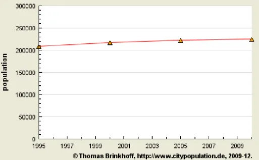
There are three cities near NAF Atsugi that required immediate attention due to their increasing populations. The city of Atsugi had a population of 208,627 in October 1995 and that increased to 224,420 in October 2010 (Brinkhoff, 2011a). Figure 1 shows the population growth of Atsugi from 1995 to 2010.
Figure 1. Population Growth Chart of Atsugi (From Brinkhoff, 2011a)
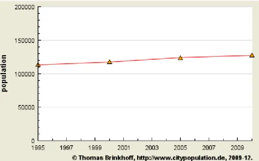
The city of Ebina had a population of 113,430 in October 1995, which increased to 127,707 in October 2010 (Brinkhoff, 2011c). Figure 2 shows the population growth of Ebina from 1995 to 2010.
Figure 2. Population Growth Chart of Ebina (From Brinkhoff, 2011c)
The city of Ayase had a population of 110,680 in October 1995, which increased to 129,167 in October 2010 (Brinkhoff, 2011b). Figure 3 shows the population growth of Ayase from 1995 to 2010.
Figure 3. Population Growth Chart of Ayase (From Brinkhoff, 2011b)
The objective of this project is to further leverage a prior thesis project titled Best Value Analysis of Movement Strategies for Carrier Air Wing Five (CVW-5) from Iwakuni to Yokosuka, Japan (Debord, Coleman, & Hodge, 2011). We use some of their findings for transportation and shipping costs to determine whether there is a cost savings to the Naval Aviation Enterprise (NAE) of dual-sited equipage and, if so, whether there is an optimal mix of tools (IMRL) that can be spread among the fixed-wing assets of CVW-5.
1. Current Operational Picture
The following major commands are institutional stakeholders in the topic of this thesis and are relevant in any decisions that the thesis data present.
a. United States Navy 7th Fleet
The United States Navy’s 7th Fleet was established on March 15, 1943, and today it is the largest forward deployed U.S. fleet in the world. It has an area of responsibility that includes the Western Pacific and Indian Oceans. Commander, U.S. 7th Fleet participated in several Pacific campaigns, including the Battle of Leyte Gulf in the Philippines during World War II as the naval combatant commander under Supreme Commander Southwest Pacific Area, General Douglas MacArthur. A few years later, on February 11, 1950, the force assumed the name that it holds today—United States Navy 7th Fleet (Commander, United States Navy 7th Fleet, 2012b). Figure 4 shows the key elements of the United States Navy 7th Fleet.
Figure 4. United States Navy 7th Fleet Elements (From Federation of American Scientists, 1999)
The United States Navy’s 7th Fleet units have participated in every major military operation since being established in 1950. During the Korean War, the first Navy jet aircraft used in combat was launched from a Task Force 77 carrier on July 3, 1950, and the famous landings in Inchon, Korea, were conducted by the United States Navy 7th Fleet amphibious ships. The battleships USS Iowa (BB 61), USS New Jersey (BB 62),
USS Missouri (BB 63), and USS Wisconsin (BB 64) all served as flagships for Commander, United States Navy 7th Fleet during the Korean War. This fleet has participated in all combat operations, including Vietnam and the Global War on Terrorism (Commander, United States Navy 7th Fleet, 2012b).
Within hours of the March 11, 2011, devastating earthquake and tsunami that struck northern Japan, the United States Navy 7th Fleet mobilized 22 ships, 132 aircraft, and more than 15,000 personnel to support the Japan Self-Defense Forces (JSDF) in the largest recovery effort in their history. The relief operation that followed was named Operation Tomodachi, after the Japanese word for “friend” (Commander, United States Navy 7th Fleet, 2012b). This operation demonstrated the quick responsiveness and flexibility of the United States Navy 7th Fleet and showed the strong bonds that tie relations between the U.S. and Japan.
b. NAF Atsugi
NAF Atsugi is the only naval installation supporting an entire air wing and is located 25 miles northwest of CFAY. It has been home to U.S. Navy personnel and their families for over 50 years. The base consists of approximately 1,249 acres and lies in the Kanto Plain region on Honshu, the main island of Japan. NAF Atsugi’s strategic importance has been key to CVW-5’s success by providing state-of-the-art facilities, maintenance, and logistics services to support the “Tip of the Sword” in the Western Pacific (Commander, Navy Installations Command [CNIC], 2012b). Figure 5 shows a relational map of NAF Atsugi.
Figure 5. Relational Map of NAF Atsugi (From Ruskin & Strobel, 2011)
c. Fleet Activities Yokosuka
CFAY is a 560-acre forward deployed naval base located near Yokohama. It is the Navy’s largest, most strategically important overseas installation; CFAY has 82 tenant commands assigned to support operating forces in the Western Pacific, from Hawaii to the Persian Gulf. The base’s primary mission is to support the 11 high operational tempo warships forward deployed to Yokosuka and the United States Navy 7th Fleet flagship, USS Blue Ridge (LCC 19; CNIC, 2012a). Figure 6 shows an aerial map of CFAY.
Figure 6. Aerial Map of Commander, Fleet Activities Yokosuka (From Powers, 2012)
d. USS George Washington (CVN 73): Forward Deployed Carrier
In September 2008, USS George Washington (CVN 73) replaced USS
Kitty Hawk (CV 63) at a cross-decking ceremony in San Diego, making her the only forward deployed carrier in the Pacific (CNIC, 2012b). Figure 7 shows the USS George Washington arriving to her new home port of CFAY.
Figure 7. USS George Washington (CVN 73) Arriving New Homeport CFAY (From Davis, 2008)
e. Carrier Air Wing Five
CVW-5 has proudly earned the nickname as the nation’s only “911” air wing. It is a combat strike element of the United States Navy’s 7th Fleet and is the nation’s only forward deployed carrier strike group. CVW-5 consists of Strike Fighter Squadron 27, Strike Fighter Squadron 115, and Strike Fighter Squadron 195, each flying F/A-18E Super Hornets; Strike Fighter Squadron 102, flying the F/A-18F Super Hornet; Electronic Attack Squadron 141, which will be flying the E/A-18G (Growler) in the near future; Carrier Airborne Early Warning Squadron 115, flying the Hawkeye 2000; Fleet Logistics Support Squadron 30 Detachment 5, flying the C-2 Greyhound; and Helicopter Antisubmarine Squadron 14, flying the HH-60F/H Seahawk (CNIC, 2012b). CVW-5 has
been stationed at NAF Atsugi for over 28 years and is the only permanently forward deployed carrier air wing in the U.S. Navy. Figure 8 shows CVW-5 fixed-wing assets flying over Mt. Fuji.
Figure 8. CVW-5 Aircraft Flying Over Mt. Fuji (From Airliners, 2011)
f. Marine Corps Air Station Iwakuni
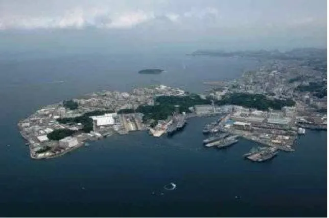
MCAS Iwakuni, Japan, is located approximately 600 miles southwest of Tokyo. The base is home to almost half of the 1st Marine Aircraft Wing that is headquartered on Okinawa, elements of the 3rd Force Service Support Group, Fleet Air Wing 31 of the Japan Maritime Self-Defense Force (JMSDF), and other units of JMSDF. The base is home to numerous F/A-18C/Ds. It presently has approximately 15,000 personnel, including Japanese national employees in five major tenants (U.S. Marine Corps [USMC], 2012a). Figure 9 shows an overhead view of MCAS Iwakuni.
Figure 9. Overhead View of MCAS Iwakuni (From Military Bases, 2012)
(1) The Mission of Marine All-Weather Fighter Attack Squadron 242 (VMFA-242) is “to support the MAGTF commander by providing supporting arms coordination, conducting reconnaissance, and destroying surface targets and enemy aircraft day or night under all weather conditions during expeditionary, joint, or combined operations” (USMC, 2012b).
(2) The Mission of Marine Aircraft Group 12 (MAG 12) is “to conduct anti-air warfare and offensive air support operations in support of Fleet Marine Forces from advanced base, expeditionary airfields or aircraft carriers and conduct such air operations as may be directed” (USMC, 2012b).
(3) The Mission of Marine Aviation Logistics Squadron 12 (MALS 12) is “to provide aviation logistics expertise, planning and material to
MAG-12 and its subordinate tactical aircraft squadrons in order to support operational contingencies, theater security cooperation plans, and training exercises in the Pacific Command area of responsibility” (USMC, 2012b).
(4) The Mission of Marine Wing Support Squadron 171 (MWSS 171) is to provide all essential Aviation Ground Support requirements to a designated fixed-wing component of an aviation combat element and all supporting or attached elements of the Marine Air Control Group. Additionally, the squadron has the implied mission to supplement airbase facilities and services at MCAS Iwakuni. Forming an essential element of Marine Wing Support Group 17 and 1st Marine Aircraft Wing, Marine Wing Support Squadron 171 routinely fulfills its demanding responsibilities in Iwakuni and also in deployed locations around the Pacific Rim (USMC, 2012b).
The Marine Corps Aviation Ground Support performs the following 14 functions (USMC, 2012b):
1. internal airfield communications; 2. weather services;
3. expeditionary air fields (EAF) services; 4. aircraft rescue and firefighting (ARFF); 5. aircraft and ground refueling;
6. explosive ordnance disposal; 7. essential engineer services; 8. motor transport;
9. field mess facilities;
10. sick-call and aviation medical functions;
11. individual/unit training of organic and selected personnel; 12. nuclear, biological, and chemical defense;
13. security and law enforcement services; and 14. air base commandant functions.
(5) The mission of Marine Wing Support Group 17 (MWSG 17) is “to provide essential ground support requirements (less aircraft supply, maintenance,
and ordnance) to a designated MAW. The MWSG is organized and equipped for employment as an integral unit in support of the MAW” (USMC, 2012b).
g. Maintenance Labor
Japanese workers on U.S. military bases in Japan are hired under bilateral labor contracts, the master labor contract (MLC) and the indirect hire agreement (IHA). MLC positions are open only to permanent residents of Japan who are not U.S. civilian employees for the military, Service members, or their family members. IHA positions are available to permanent residents of Japan who are not U.S. citizens. The unique nature of the labor agreements has caused friction, at times, between Japanese employees and U.S. supervisors. There are approximately 8,900 MLC and IHA employees working on 23 military facilities, according to the Labor Management Office, the Japanese government’s labor administration office for MLC and IHA workers for U.S. Forces Japan (Sumida, 2004).
2. Pending Operational Picture
As a direct result of the U. S.–Japan SCC document of October 29, 2005 (Rice et al., 2005), the Navy will relocate approximately 64 CVW-5 fixed-wing assets from NAF Atsugi to MCAS Iwakuni in 2016. Figure 10 shows a relational map between the current situation in Atsugi and the future location for CVW-5 fixed-wing aircraft. The move will not affect the helicopter squadrons because they will remain at NAF Atsugi. Figure 10 shows a relational map of U.S. military bases in Japan.
Figure 10. Relational Map of U.S. Military Bases in Japan (From Debord, Coleman, & Hodge, 2011)
When CVW-5 relocates in 2016 to MCAS Iwakuni, the standard operating procedure for them would be to take their entire tools/IMRL equipage with them. In this project, we examine the current tools/IMRL transportation process, CVW-5 transportation options, along with CVW-5 transportation options, and the redundancies and costs associated with these options. This analysis may be used as a decision and evaluation tool to support the procurement, distribution, and accountability policy for CVW-5’s fixed-wing tools/IMRL.
3. About This Thesis
In this project, we analyze Tools/IMRL requirements for CVW-5 fixed-wing assets, and we determine whether there is a more beneficial quantity and distribution of these assets throughout the dual sites of CFAY–MCAS Iwakuni. In Chapter II, we outline our assumptions and data-collection techniques.
II. TOOL/INDIVIDUAL
MATERIAL READINESS LIST
PRACTICES
The function of the second chapter is to provide an understanding of the classes of material utilized in the maintenance and material support of an air wing and the level of oversight provided for the oversight of these materials. The limitations that governing references and responsible entities impose must be understood and addressed prior to making any changes to outfitting quantities and procedures as they exist under the current paradigm.
A. INDIVIDUAL MATERIAL READINESS LIST
IMRL items are a subset of the class of items known as aircraft maintenance material readiness list (AMMRL) items (Commander, Naval Air Forces [CNAF], 2009). AMMRL items encompass a wide range of assets used at all levels of aviation maintenance, from large ground-support equipment (GSE) items, such as hydraulic generators, to intricate test program sets (TPS) used in the repair of complex electronic weapons replaceable assemblies (WRA). The primary objective of the AMMRL program is to provide operational IMRL support equipment to satisfy flight and personal safety requirements in direct support of mission effectiveness (CNAF, 2008). Across the fleet, there are approximately 37,000 discrete line items of AMMRL assets that are managed and used in aircraft maintenance evolutions at all levels (CNAF, 2009). Many IMRL assets are very specialized to a particular application and, therefore, have a scarcity and high cost associated with their procurement. For this reason, the Navy maintains databases at two levels to track these assets, as well as implements stringent requirements directing inventory managers to maintain strict control of their assigned catalog of items.
1. Governing References
The primary reference governing the management of AMMRL, and by extension IMRL, assets is the Naval Aviation Maintenance Program (NAMP) COMNAVAIRFORINST 4790.2A CH-2 (CNAF, 2009). In the third chapter of this report, we cover maintenance concepts, programs and processes, maintenance unit
departments, division organization, manpower management, and aviation officers; the applicable section is the area on programs and processes. The NAMP functions as a high-level guidance document for the programs it covers, and the details of individual programs are governed by specific references indicated by the NAMP for adherence to applicable standard operating procedures. In the case of AMMRL, the NAMP refers readers to the NAVAIRINST 13650.1 series for allowance and inventory control procedures, to the NAVAIRINST 13680.1 series for rework procedures, and to the NAVAIR 17-35MTL-1 series for calibration requirements of AMMRL assets (CNAF, 2009).
2. Coding of Assets
IMRL assets are assigned single-digit alphabetic codes to designate the type of item covered and to provide additional information on the type of transaction required for requisitioning the item (CNAF, 2008). The codes themselves are tied to supply and financial records for accountability purposes. The type of IMRL assets that are assigned reporting codes are the ones that are allocated to intermediate maintenance activities (IMA) and Fleet Readiness Centers (FRCs) for sub-custody to other activities (CNAF, 2009). The primary custody codes used are the following:
a. Code P
Large items, in excess of 200 pounds for immobilized equipment or 300 pounds for wheeled equipment, which exceed certain storage size authorizations. This category of IMRL also includes assets that are too fragile or likely to have their calibration coverage voided through misalignment during movement, limiting their transportability. Assets of this category are checked out to hosted commands by the applicable IMA when required for local operation (CNAF, 2008).
b. Code D
Items in a detachment list that have a code of D or E. The D code allows items assigned to a specific detachment to be grouped together for management, but this code is still subject to the same requirements of a P-coded item (CNAF, 2008).
c. Code E
Infrequently used items that are utilized on an average periodicity of less than once per month. These items are provided to the cognizant IMA and checked-out only to hosted activities for immediate use (CNAF, 2008).
d. Code M
Generic IMRL items that are not calibrateable and that are not covered by any other custody code. These units are issued and used in conjunction with calibrateable items (CNAF, 2008).
e. Code N
IMRL items that do not require calibration and are not covered by any other custody code (CNAF, 2008).
f. Code L
Items that do require calibration and management and are sub-custodied to organizational activities for use both while deployed and in homeport which are not covered by any other custody code (CNAF, 2008).
3. Responsible Levels
The list that follows describes the primary levels associated with IMRL program management and compliance. We highlight the principal responsibilities of these parties in this thesis, but a full listing of responsibilities can be found in the NAMP and the NAVAIRINST 13650.1 series publication.
a. Aviation Support Equipment Program Manager
The activity designated as the overall aviation SE program manager is COMNAVAIRSYSCOM (PMA-260). PMA-260 holds responsibilities at all levels of the support equipment life cycle, from initial design through development and testing, and into operational use. PMA-260’s responsibility concludes only with asset disposition upon retirement. PMA-260 is also responsible for the funding of initial IMRL procurement of all covered activities. As part of the PMA-260 management of the operational life of a
support equipment asset, this activity also governs the technical documentation and training necessary to field the equipment and keep it in a useful status (CNAF, 2009).
b. Support Equipment Controlling Authority
The support equipment controlling authority (SECA) maintains an accurate accounting in the support equipment resource management information system (SERMIS) for all equipment in the custody of its responsible commands. By extension, the SECA is responsible for determining the authorized allowance of IMRL for weapons systems operated in its area of responsibility; the SECA must first approve any transfers of equipment or requests for asset augmentation prior to execution. Compliance with AMMRL procedures is accomplished thorough training provided to area commanders and a monthly transaction report verification conducted with reporting activities (CNAF, 2008).
c. Area Commander
The area commander is the appointed representative for the SECA within a specific geographic area of responsibility. The Area Commander ensures that subordinate activities remain in compliance with standard AMMRL procedures by making certain that only knowledgeable and qualified personnel are assigned to positions of authority in program management. A large component of this compliance is the maintenance of accurate Local Asset Management System (LAMS) files within the organizations as well as quarterly generated back-up records. Another, and also important, compliance requirement by the Area Commander is to ensure the accurate processing of the mandatory wall-to-wall IMRL inventories at the appropriate level and within prescribed periodicities (CNAF, 2008).
d. Activity Level
Physical compliance with AMMRL program requirements is accomplished at this level through interaction between the maintenance officer, respective division officers, work center supervisors, material control, and the assigned IMRL asset manager. At the top of the activity hierarchy, the maintenance officer (MO) must appoint an IMRL asset manager at least 30 days prior to the departure of the previous IMRL manager. The
assigned manager must be an E-5 or above and hold the IMRL management Naval Enlistment Code 9590. The requirement for the overlap is to enable the prospective manager to become familiar with the IMRL condition within the command prior to the departure of the previous subject-matter expert. The maintenance officer must also sign as the responsible officer on all surveys (DD Form 200) that are submitted for IMRL discrepancies (CNAF, 2008).
Division officers administratively maintain all IMRL for their assigned divisions and report compliance status to the maintenance officer for the completion of program requirements. The principal agents of the division officer in program compliance are the individual work center supervisors. The division officer reviews IMRL documents prior to up-line submission (CNAF, 2008).
The work center supervisors are the frontline IMRL managers who maintain an accurate listing of all assigned assets. They are charged with conducting the physical inventories and initiating the surveys for any discrepancies with assigned gear (CNAF, 2008).
The material control work center supervisor is responsible for ensuring the activity’s compliance with AMMRL procedures and reporting its conformance to the maintenance officer. The IMRL asset manager is the agent who spearheads compliance activities. In addition to verifying the compliance of other activity levels with program requirements, the asset manager also performs administrative tasks to keep the activity on track, such as maintaining a 100% local asset management system (LAMS)-to-support equipment resource management information system (SERMIS) accuracy and submitting IMRL disposition requests as necessary. Due to their superior knowledge of the program, asset managers provide program training to all activity personnel (CNAF, 2008).
4. Outfitting
Outfitting entails the procedures in place to achieve the equipage of valid IMRL requirements for operational activities. The mechanics of outfitting are described in the following list:
a. Methods
(1) Push—Assets purchased through NAVAIR-appropriate funds with no charge to the recipient activity. The support equipment controlling authority (SECA) and NAVAIR determine how assets should be allocated according to need, and site activation teams or the actual manufacturer of the equipment deliver the resources (CNAF, 2008).
(2) Pull—Performed with IMRL funding provided to an activity to ensure adequate material exists to cover maintenance activities and to facilitate the support of hosted activities (CNAF, 2008).
(3) Redistribution—The transfer of excess materials from one existing activity to another and the repurposing of material from eliminated activities (CNAF, 2008).
(4) Local manufacture—Assets that are not procured in their final form from a commercial source but are manufactured at the local level using technical data from the Naval Air Technical Data and Engineering Services Command (CNAF, 2008).
b. Occasion
(1) Initial outfitting—The function of providing IMRL assets to newly established activities under the coverage of an SECA. The SECA determines the asset requirements of the prospective activity approximately one year prior to its implementation and provisions the activity through either push or redistribution channels (CNAF, 2008).
(2) Re-outfitting—This process results from changes in the scope of an SECA-supported activity in which new requirements or operating environment changes nullify the previously existing IMRL authorization for the activity. Approximately one year prior to the change, the SECA will assess requirements driven by the changes in the supported activity’s position and outfit the activity to the proper level through push, pull, and redistribution (CNAF, 2008).
5. Tracking Databases
The Navy uses two databases to track and allocate AMMRL based on the needs of fleet end users. The SERMIS is the higher level database SECAS use that contains information that subordinate activities provide up line (CNAF, 2009). The LAMS database is operated and maintained by local element commands as a method of updating the SERMIS and ensuring that a full picture of material availability is provided fleet wide (CNAF, 2008). The key source data that links the two databases is the Support Equipment Transaction Report (OPNAV 4790/64; CNAF, 2009). The existence of this form’s fields in both databases enables one to feed the other. Further explanation of each program is provided in the following list.
a. Support Equipment Resource Management Information System
The SERMIS is a program fielded by COMNAVAIRSYSCOM PMA 260EA to identify and catalog the technical items used by all organizational, intermediate, and depot-level maintenance activities to perform repairs and upkeep on Navy aviation assets. The purpose of the data contained in the system is to provide SECAs with inventory control oversight into source, allowance, and inventory data from an electronic perspective (CNAF, 2009). In addition to the asset-tracking features of LAMS, the broader-scope architecture of the SERMIS facilitates redistribution of assets across activities, enables the scheduling of rework for listed assets, and makes configuration management of resources possible across varying platforms.
b. Local Asset Management System
The LAMS is also a computer-based program fielded by COMNAVAIRSYSCOM, but its purpose is the management of assets at the local command level, rather than on a fleet-wide basis. To standardize input to the SERMIS from the numerous individual AMMRL controlling commands, the LAMS is the only program authorized for use at the local level, and all support equipment transactions must be processed in this system. Prompt transaction report updates within this system ensure inventory accuracy across the aviation enterprise (CNAF, 2009).
6. Transfer Procedure
The transfer of IMRL from the permanent custody of one activity to another can be performed only under the direction of the SECA. Transfer authority is requested from the SECA through the completion of a formal IMRL revision request (IRR) on the part of the activity appealing for a tailoring of their asset allowance in an amount either upward or downward of what they are currently allotted. The processing of the IRR, as with all AMMRL actions at the activity level, is conducted within the LAMS to ensure uniformity across all fleet-level users. Once the SECA has issued transfer authority, the losing activity must perform a transfer inspection on the selected items and transport them in a ready-for-issue status to the nearest local supply department within 30 days. If the items cannot be shipped within the standard 30-day interval, a detailed explanation must be presented to the SECA specifying the reason and requesting an extension. The deadline for transmission of a message notifying the SECA of the non-availability of the identified assets is 15 working days from the date that the transfer notification was authorized. If the asset transferred requires a historical record (OPNAV 4790/51) for annotating the usage of the item, then the original copy of that record must also be transferred to the gaining activity. The gaining activity is required to proactively monitor the LAMS for incoming items and to request a survey for in-transit loss if items are not received within 180 days of the transfer authorization. The gaining activity must perform an acceptance inspection on items received; if items are received in any condition other than ready for immediate use, then the gaining activity is also tasked with contacting the SECA for further direction. The return of non-functional items to the point of origin without SECA approval is unauthorized (CNAF, 2008).
7. Accountability Requirement
For proper accountability of IMRL assets, inventories must be conducted at certain mandatory intervals. Further inventories during daily usage are recommended but not required under the guidelines of the AMMRL program. All occasions for IMRL inventory must be performed in a wall-to-wall format, so named because the physical location of all items the activity is accountable for must be physically verified (CNAF, 2009). The four requisite intervals for inventory are as follows:
a. Annual Inventory
Completion of the annual inventory is reported to the SECA and must be done once every calendar year, with the additional restriction that 18 months cannot be exceeded between performances of subsequent inventories (CNAF, 2008).
b. Maintenance Officer Relief Inventory
The maintenance office relief inventory is conducted as part of the turnover process between maintenance officers and has a completion deadline of 30 days from the assignment of the new maintenance officer. This inventory can be performed in conjunction with the annual requirement, and no outside reporting is required of this inventory unless it is also used as the annual inventory (CNAF, 2008).
c. Work Center Quarterly Inventory
The work center inventory is performed once each quarter of the calendar year to report the condition of all IMRL assigned to the work center and in its custody. Compliance is the division officer’s responsibility and is reported to the maintenance officer (CNAF, 2008).
d. Sub-Custody Quarterly Inventory
The sub-custody inventory is performed once each quarter of the calendar year to report the condition of all IMRL assets assigned to activities that have been checked out to another hosted activity. Compliance is the responsibility of the maintenance material control officer of the hosted activity and is reported to the maintenance officer of the hosting activity (CNAF, 2008).
B. TOOLS
The Tool Control Program (TCP) is based on the concept of a family of specialized toolboxes and pouches configured for instant inventory before and after each maintenance action. The content and configuration of each container is tailored to the task, work center, and model aircraft maintained. Normally, tool containers are assigned
to and maintained within a work center. However, if considered necessary and space permits, a tool control center (tool room) may be established (Commander, Naval Air Systems Command, 2004).
There are numerous maintenance actions that may be required to service and repair Navy and Marine Corps aircraft. There could be hundreds of different types of maintenance requirements, each with its own unique set of tools. In addition, space limitations on an aircraft carrier necessitate the use of compact toolboxes containing only the necessary tools required for each specific maintenance action. NAVAIR Lakehurst is responsible for designing and developing customized toolboxes and manuals to accommodate maintenance and tooling requirements for most Navy aircraft and their support equipment. Information is taken from the tool control manuals and used to design toolboxes for specific maintenance tasks listed in the manuals. This eliminates the need for toolboxes containing tools that are not needed, which saves money, time, and space. Each tool has an assigned location within the toolbox to help keep track of all the tools within the box and quickly identify any missing tools. The NAVAIR Lakehurst team is currently working on developing toolkits for a number of Navy aircraft programs, which include the V-22, F-18, T-45, and H-60 support equipment programs (Naval Air Warfare Center, 2010).
1. Governing References
The primary reference governing the management of tools used for aviation maintenance purposes is the NAMP. The NAMP functions as a high-level guidance document for the programs it covers. The details of individual programs are governed by specific references that the NAMP indicates for adherence to applicable standard operating procedures. In the case of tools, the NAMP refers readers to the Naval Air Systems Command (NAVAIR) Tool Control Manual series (CNAF, 2009).
a. Naval Aviation Maintenance Program
The NAMP is sponsored and directed by the Chief of Naval Operations (CNO) and is implemented by Commander, Naval Air Forces (COMNAVAIRFOR). The Commander, Naval Air Forces Instruction (COMNAVAIRFORINST) 4790.2 series
(CNAF, 2009) addresses maintenance policies, procedures, and responsibilities for the conduct of the NAMP at all levels of maintenance throughout naval aviation. It is considered the bible of naval aviation maintenance and takes precedence over all other aviation-related maintenance manuals (CNAF, 2009).
b. Tool Control Program
The TCP establishes policy and responsibilities for implementing, maintaining, controlling, storing and replacing common hand tools. It is applicable to all Navy and Marine Corps O-level and IMA/commander, Fleet Readiness Center (COMFRC) activities performing or supporting aircraft maintenance. In addition, the TCP applies to all commercial and other government activities that perform contract maintenance, production, or other type of support functions on naval aircraft. The purpose of the TCP program is to assist the warfighter by providing an instant inventory capability through tool containers that have been internally tailored with each specific tool positioned in a unique location. These tool locations are typically silhouetted and provide a quick and accurate method for identifying tools that are missing, because missing tools can cause catastrophic results to aircrew and/or aircraft. The primary objectives of the TCP are to heighten safety by eliminating accidents and equipment damage attributed to uncontrolled tools and minimizing tool-replacement costs. As per the CNAF, an effective TCP is the responsibility of all maintenance personnel at every level of the chain of command (CNAF, 2009).
(1) NAVAIR 17, Tool Control Manuals (Series)
The information presented in these NAVAIR 17 manuals includes procedures, methods, and detailed instructions for the operation of the tool control program; the duties of key personnel; materials lists; container identification; and tool container/fixture fabrication instructions, container layouts, and tool inventories. The procedures contained in these manuals have previously proven themselves to be effective and are necessary for the positive control and accountability of tools (Commander, Naval Air Forces, 2009).
(2) NAVAIR 17-1FA18-1
NAVAIR 17-1FA18-1 (Commander, Naval Air Systems Command, 2007) is the Aircraft Tool Control Manual for all Navy and Marine Corps F-18 Aircraft. The purpose of this technical manual is to present the TCP for Navy and Marine aviation organizational maintenance activities. The main objective of the TCP is the prevention of the aircraft accidents, incidents, and foreign object damage (FOD) that have been factors when tools were left unaccounted for. Some additional benefits that are realized by compliance with the procedures in the manual are the reduction of pilferage, initial outfitting costs, in-use inventories, tool replacement costs, and maintenance man-hours. The reduction of any of these items makes significant contributions to cost effectiveness (Commander, Naval Air Systems Command, 2007).
(3) NAVAIR 17-1E2C-1
NAVAIR 17-1E2C-1 (Commander, Naval Air Systems Command, 2004) is the Aircraft Tool Control Manual for all Navy and Marine Corps E2C Hawkeye Aircraft. It fulfills the same objectives as the F/A-18 series manuals, but for the Hawkeye platform.
2. Compliance with these Tool Control Manuals
Compliance with and implementation of these tool control manuals is the responsibility of the respective aviation squadrons who are designated as the aircraft controlling custodian (ACC) and/or the type commander (TYCOM). These requirements are established in Office of the Chief of Naval Operations Instruction OPNAVINST 4790.2 (Commander, Naval Air Systems Command, 2004).
3. Responsibilities: O-Level, I-Level, and COMFRC Activities
a. Aircraft Controlling Custodians
ACCs may designate subordinate activities as tool control model managers for specific type/model/series (TMS) aircraft (CNAF, 2009).
b. The Maintenance Officer/Fleet Readiness Center Equivalent
The MO/FRC equivalent develops local command procedures, when necessary, which outline a comprehensive, integrated, and monitored TCP in areas where tooling is required for the performance of aircraft, aircraft component, and related equipment maintenance, rework, and installation. (It is during the development of command procedures that any pooling of resources between similar T/M/S aircraft and co-location of resources may be identified; CNAF, 2009.)
c. The Assistant Maintenance Officer/Industrial Training Department
The assistant maintenance officer/industrial training department provides all the required training requirements on the TCP to all aviation maintenance personnel. In particular, the training provided emphasizes personnel TCP responsibilities and missing tool procedures (CNAF, 2009).
d. The Maintenance Material Control Officer /Production Control Officer
The maintenance material control officer (MMCO)/production control officer establishes tool control centers, when necessary, and is designated as the approving authority to add, delete, or modify tools. These tool room establishments are usually manned by Sailors from work centers and are not necessarily provided for in the squadron’s manpower documents. This can lead to each F/A-18 squadron having its own unique tool room, each carrying similar items of tools/IMRL(CNAF, 2009).
e. The Program Manager/Coordinator
The program manager/coordinator designates in writing a TCP coordinator/subject-matter expert (SME) and ensures the proper operation of the tool control work center. Additionally, he or she reviews all aviation fleet maintenance (AFM) fund purchases or FRC operations and maintenance/Navy (O&MN) requisitions submitted by the TCP coordinator for the purchase of spare or replacement tools to screen for any unauthorized or excess tool purchases. AFM funds are used to maintain and support the
manager/coordinator are to budget and plan AFM funds for O-level aviation activities or O&MN for FRCs in the procurement of approved tool containers and hand tools (CNAF, 2009).
4. TCP Implementation
When a tool control manual (TCM) does not exist for a specific T/M/S aircraft, the reporting custodian develops a local TCM and is submitted via his or her chain of command to the cognizant type-wing for approval. All Navy and Marine Corps aviation activities utilizing NAVAIR 17 series TCMs identify the particular tools they require using the tool inventory list that the TCM provides. Intermediate maintenance activities ashore and activities that are not on an established TCM determine the tools necessary to perform repetitive tasks in each work center and develop a local tool inventory list. These lists identify each tool by item number, nomenclature, specific quantity, and national stock number (NSN). Each tool is etched whenever physically possible, including all pieces of a set. This procedure can be very tedious and time consuming when multiple type boxes are designated for a work center. Tools that are too small to etch are identified by an asterisk (*) in the tool container inventory list (CNAF, 2009).
5. Tool Containers
All Navy and Marine Corps aviation activities utilizing NAVAIR 17 series TCMs shall establish tool container configurations per the TCM. It is mandatory that all hardware placements, such as clips and brackets, and the drilling of holes are exactly as indicated in the drawings. These tool containers must be numbered with the applicable aviation organization code, work center code, and container number (for example, AC3-110-2). If the work center authorizes more than one of the same type tool container, the additional containers are identified with a numerical suffix (for example, AC3-110-2-1). In addition, the position of each individual tool is silhouetted against a contrasting background to assist in identifying any missing tools and to ensure an accurate inventory. Every individual tool location is numbered with a corresponding number on the tool container inventory list. A copy of the TCM inventory list, TCM diagram, and tool container shortage list is placed and firmly attached within all tool containers so that
they do not become sources of FOD. A brief explanation of FOD and the dangers it poses is explained at the end of this section (CNAF, 2009).
6. Proposed Changes, Deviations, and Additions
The warfighter is encouraged to suggest improvements to the NAVAIR 17 series manuals. Any proposed changes in the tool inventory and/or container layout diagrams must be sent by technical publications deficiency report (OPNAV 4790/66), with appropriate justification, via the appropriate wing commander and ACC/TYCOM for approval/disapproval. These procedures are established in the Discrepancy Reporting Program in the NAMP. Any requests for deviation for activities with unique operational situations and/or more than one type aircraft is submitted, with appropriate justification, via the appropriate wing commander to the ACC/TYCOM for evaluation and/or approval as required (Commander, Naval Air Systems Command, 2004).
7. Foreign Object Damage
FOD is defined as a substance, debris, or article alien to the vehicle or system that would potentially cause damage. FOD is any damage attributed to a foreign object that can be expressed in physical or economic terms and that may or may not degrade the product’s required safety and/or performance characteristics. Typically, FOD is an aviation term used to describe debris on or around an aircraft, or damage done to an aircraft (FOD Control Corporation, 2007).
FOD has been a part of naval aviation accidents since the earliest days of flight, whether it was propeller nicks, tire damage, or tears to airframe fabric, but FOD actually started getting the visibility it needed with the introduction of the jet engine. FOD includes loose hardware, extra parts, pieces of runways, pens, coins, garbage, and wildlife. Basically, anything that can cause damage to an aircraft engine, flight controls, or fuel systems falls under the definition of FOD. FOD can be found anywhere in the aviation environment, from the runway to the manufacturing plant and hangars. FOD damage has often resulted in catastrophic events, leading to loss of life and valuable equipment. The National Aerospace FOD Prevention Inc. estimates the cost of FOD to the global aerospace industry at $4 billion annually. This sum is due mainly to repairing
aircraft engine damage caused by the ingestion of FOD. The FOD program in naval aviation came into being due to the fact that almost all FOD incidents are entirely preventable(FOD Control Corporation, 2007).
In the following chapter, we will discuss the primary data sources and analysis techniques used in our model.
III. METHODOLOGY
AND REFERENCE DATA
The third chapter of this document encompasses the primary data sources, analysis techniques, and assumptions upon which our analysis of the tool and IMRL outfitting procedures are based. We list methodology that is common to all analysis formats to prevent redundancy when switching between evaluation techniques. We introduce any analysis techniques or assumptions that are peculiar to a specific model in Chapter IV at the same time as the model itself.
A. DATA SOURCES
The primary resources listed in the data sources section were our informational foundation when constructing this document. The persons listed by name or title are the subject matter experts in their specific area and the publications are the governing reference for their respective discipline. Clarification of assumptions integral to the calculations of this document can be referred back to these sources of expert knowledge for verification of policy adherence.
1. Brian Kudrna
The primary point of contact for interface between our project research team and the CVW-5/Marine Activity Group (MAG)-12 Integrated Transition Team for Commander, Naval Air Forces (CNAF)/Commander, Naval Air Force Pacific (CNAP) in San Diego. Kudrna coordinated and consolidated all information requests that were made to gather source data on CVW-5 transition planning. Additionally, he spearheaded our drive to collect cost data for aerospace maintenance materials.
2. Raymond D. Wendrzycki
NAVAIR Aircraft Tool Control Program Manager. Wendryzycki provided all Hornet Tool data, including cube dimensions and costs, for all CVW-5 Hornets and fixed wing assets.
3. David A. Dougherty
CSFWP IMRL Manager. Dougherty provided all Hornet IMRL data, including cube dimensions and costs for all CVW-5 Hornets and fixed-wing assets.
4. CVW-5 Maintenance Officer
Subject-matter expert and decision authority for air wing maintenance planning. Michael Washington provided the research team with information specific to CVW-5 operations and requirements through interaction with Brian Kudrna.
5. CNAF Publications
Referenced for regulations and procedures governing the materials used in aerospace maintenance under Navy cognizance.
6. Type/Model/Series Publications
Provided information peculiar to the individual classes and variants of aircraft comprising CVW-5.
7. NAF Atsugi to MCAS Iwakuni Transition Planning Documents
Provided data relating to the reason, timeframe, and magnitude of the air wing relocation, which we could analyze for planning purposes.
B. ANALYSIS TECHNIQUES
One of the goals of NAVAIR’s “Supporting Sea Power-21” is to reduce the cost of doing business throughout the NAE. One tool is AIRSpeed, which is a philosophy, strategy and a proven set of tools that enables NAVAIR and the NAE to achieve cost-wise readiness. It is a means of reducing the cost of doing business, improving productivity, and increasing customer satisfaction. The NAE is guided by NAVAIR AIRSpeed, which emphasizes applying the tools of continuous process improvement to non-production, transactional service environments. Utilizing theory of constraints, Lean, and Six Sigma methodologies, personnel at all levels are improving ways to change how the NAE does business at every level of the organization: headquarters, business unit, department, program office, and integrated product team. Just because a process has been done a
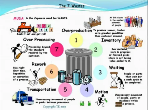
certain ways for years, it does not mean that it must not be under constant, vigilant review. There might be cost savings that could be realized to the NAE if the process were improved or if unnecessary steps were removed. Some of these unnecessary steps that are considered waste in Lean/Six Sigma go by the acronym of TIMWOOD: Transportation, Inventory, Motion, Waiting, Over-Production, Over-Processing, and Defects (Miller, 2007). The analysis, removal, or reduction of any of these seven forms of waste can reduce overall costs, resulting in savings that may be reallocated in a more efficient manner. AIRSpeed also emphasizes continuous process improvement (CPI), which is another tool that is often used to fix problems; it is easily available to all personnel and can deliver significant benefits (CNAF, 2012). The use of many of these AIRSpeed
methodologies in this analysis may assist decision-makers in determining the best course of action on whether CVW-5 should procure a duplicate set of tools (IMRL) or whether there is a better mix of alternative actions. Figure 11 depicts the seven wastes known by the acronym TIMWOOD.
Figure 11. Chart of TIMWOOD (Google, 2012)