Disclosure to Promote the Right To Information
Whereas the Parliament of India has set out to provide a practical regime of right to
information for citizens to secure access to information under the control of public authorities,
in order to promote transparency and accountability in the working of every public authority,
and whereas the attached publication of the Bureau of Indian Standards is of particular interest
to the public, particularly disadvantaged communities and those engaged in the pursuit of
education and knowledge, the attached public safety standard is made available to promote the
timely dissemination of this information in an accurate manner to the public.
इंटरनेट
मानक
“
!ान $ एक न' भारत का +नम-ण
”
Satyanarayan Gangaram Pitroda
“Invent a New India Using Knowledge”
“
प0रा1 को छोड न' 5 तरफ
”
Jawaharlal Nehru“Step Out From the Old to the New”
“
जान1
का
अ+धकार
,
जी1
का
अ+धकार
”
Mazdoor Kisan Shakti Sangathan
“The Right to Information, The Right to Live”
“
!ान एक ऐसा खजाना > जो कभी च0राया नहB जा सकता ह
ै
”
Bhartṛhari—Nītiśatakam
“Knowledge is such a treasure which cannot be stolen”
“Invent a New India Using Knowledge”
ह
ै
”
ह
”
ह
IS 10743 (1983): Method for Determination of Centre of
Gravity of Agricultural Tractors [FAD 11: Agricultural
Tractors and Power Tillers]
IS:10743- 1983
Indian Standard
METHOD FOR
DETERMINATION OF CENTRE OF
GRAVITY OF AGRICULTURAL TRACTORS
Agricultural Tractors and Power Tillers Sectional Committee, AFDC 52Chairman
PROF M. M. MEHTA
Representing
Escorts Limited, Faridabad; and Indian Society of Agricultural Engineers, New Delhi
Members
SHRI A. K. RAMAN ( Alternate to Escorts Limited, Faridabad Prof M. M. Mehta )
DR K. N. SINQH ( Alternate to Indian Society of Agricultural Engineers, New~Delhi Prof M. M. Mehta )
DR A. ALAM Indian Council of Agricultural Research, New Delhi SHRI A. V. ALEXANDER Escorts Tractors Limited, Faridabad
SHRI K. P. JA~N ( Alternate )
SHRI S. S. BABHULEAR Kirloskar Tractors Limited, Nasik SHRI P. N. BALGUDE ( Alternate )
SHRI BHUPENDRA National Agricultural Co-operative Marketing Federation of India Limited, New Delhi
SHRI Y. K. JAIN ( Alternate )
SHRI CHANDRA MOHAN
SHRI G. S. RIHAL ( Altcrnatc I ) Punjab Tractors Limited, Mohali ( Punjab ) SHRI S. S. GREWAL ( Alternate II )
SHRI C. B. COUTH Indian Investment Centre, New Delhi
SHRI M. R. DEWAN Tractor Training and Testing Station ( Ministry of Agriculture ) , Budni
SHRI J. PRASAD ( Alternate I ) SHRI R. S. DASS ( Alternate II )
DIRECTOR Central Institute of
( ICAR 1. Bhooal Agricultural Engineering
DR R. C. MAHESWARI (Alternate) ’ ” A
SHRI K. N. GAUR Central Mechanical Engineering Research Institute ( CSIR ), Durgapur
SHRI R. K. GWTA State Farms Corporation of India Ltd. New Delhi
SHRI M. L. GARQ ( Alternate )
SHRI S. C. GUPTA Harsha Tractors Limited, Ghaziabad SHRI M. S. RAO ( Alternate )
( Continued on page 2 ) @I Copyright 199 1
INDIAN STANDARDS INSTITI ITION
This publication is protected under the Indian Copyright Act ( XIV of 1957 ) and reproduction in whole or in part by any means except with written permission of the publisher shall he deemed to he an infringement of copyright under the said Act
IS:10743- 1983
( Confinued from page 1 )
Members Representing
SHRI V. K. JAIN Directorate General of Technical Development
Snar T. K. B. VARMA ( Allernatc ) ( Ministry of Industries ), New Delhi SRRI G. N. MEHTA
Sun1 G. C. PATEL ( Alternate)
Gujarat Tractors Corporation Ltd, Vadodara DR V. K. MITTAL
& R. B. RAM ( Alternate ) Punjab Agricultural University, Ludhiana SHRI J. S. MuonAa
SARI G. B. LAL ( &ernaQ ) HMT Limited ( Tractor Division ), Pinjore
SHRI H. M. MUTTA Mahindra & Mahindra Ltd ( International Tractor
Division ), Bombay SHRI M. V. VENKATESWARAN ( Alternate I )
Snar A. R. SONALKAR ( Alternate 11 )
SHRI A. T. NAHENDER VST Tillers Tractors Limited, Bangalore SHRI V. P. MAHENDRA ( Alternate )
DR S. T. NARAYANASWAMY Bharat Earthmovers Ltd, Bangalore Da V. PANDURAN~A Tractors and Farm Equipment Ltd, Madras
SHRJ S. RANOANATHAN ( Alternate )
SHRI S. B. PANDYA National Farmers Organization, New Delhi
SHRI V. V. PATIL Bharat Krishak Samaj. New Delhi
SHRI K. RAMKUMA~ Kerala Agro Machinery Corporation Limited,
Ernakulam SRRI M. K. CHANDRA-
MOH ANAN NAIR ( Alternate )
SRRI B. ROY Development Commissioner ( Small Scale Industries), New Delhi
DR S. SATYAWJRTY Either Goodearth Limited, New Delhi Da J. BHATTACRARYYA ( Alternate )
SHRI N. C. SAXENA J. K. Satoh Agricultural Machines Limited, Kanpur SHRI R. K. BAJPAI ( Alternate )
SRRI K. S. YADA~ Ministry of Agriculture ( Department of Agriculture & Co-operation 1, New Delhi
SRRI T. PURNANANDAM, Director General, ISI ( Ex-o&cio Member )
Director ( Agri & Food)
Secretary
SRRI R. N. SRARMA Deputy Director ( Agri 8-z Food ), IS1
2
IS : 10743 - 1983
Indian Standard
METHOD FOR
DETERMINATION OF CENTRE OF
GRAVITY OF AGRICULTURAL TRACTORS
0.
FOREWORD
0.1 This Indian Standard was adopted by the Indian Standards Institution on 30 November 1983, after the draft finalized by the Agri- cultural Tractors and Power Tillers Sectional Committee had been approved by the Agricultural and %ood Products Division Council. 0.2 To evaluate the effect of gradients on tractive effort and stability it is important to determine the position of centre of gravity of the tractor. While formulating IS : 5994 ( Part 2 )-1979*, a need was felt to prepare a separate Indian Standard on this subject. This standard has been prepared to fulfil this need.
0.3 This standard is complementary to IS : 5994 ( Part 2 )-1979*.
0.4 In preparation of this standard assistance has been derived fr om IS0 789/6-1982 Agricultural tractors - test procedures - Part 6: Centre of gravity issued by International Organization for Standardization. An alternative method suggested by the Tractor Training and Testing Station, Budni, has also been incorporated.
0.5 In reporting the result of a test or analysis made in accordance with this standard, if the final value, observed or calculated, is to be rounded off, it shall be done in accordance with IS : 2-1960t.
1. SCOPE
1.1 This standard specifies method of determining the position of the centre of gravity of agricultural tractors.
2. DEFINITIONS
2.0 For the purpose of this standard, the following definitions shall apply.
*Test code for agricultural tractors:
( fitst revision ). Part II Laboratory and track tests tRules for rounding off numerical values ( rrviscd ).
3
IS : 10743 - 1983
2.1 Agricultural Tractors - See 2.1 of IS : 5994 ( Part 1 )-1979*.
2.2 Coordinates of Centre of Gravity - See Fig. 1,2 and 3.
2.2.1 Horizontal Fore-and-Aft Coordinate ( Symbol Z ) - The horizontal distance of the centre of gravity from the transverse reference ~plane.
2.2.2 Lateral Coordinate ( symbol y ) - The horizontal distance of the centre of gravity from the median longitudinal place of the tractor.
2.2.3 Vertical Coordinate ( symbol i;) - The vertical distance of the centre of gravity from the horizontal reference plane.
2.3 Reference Planes
2.3.1 Horizontal Reference Plane - Ground level ( a hard contact shall be assumed ),
2.3.2 Vertical Reference Plane 2.3.2.1 Transverse Plane
a) For wheeled tractor - Vertical plane containing the centre line of the rear axle; in case of articulated tractors locked in a straight line.
b) For crawler tractor - Vertical plane containing the centre line of the driving sprocket axle.
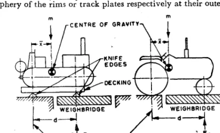
2.3.2.2 Median Longitudinal Plane - The median plane of the wheel or track assembly is equidistant from the two planes containing the periphery of the rims or track plates respectively at their outer edges.
m m
CENTRE OF GRAVltv
REFERENCE LINE
IA IB
FIG. 1 DETERMINATION OF HORIZONTAL FORE-AND-AFT COORDINATE (8)
*Test code for agricultural tractors: Part 1 Terminology and general guidelines ( jrsf revision ) .
4
IS:10743-
1983
.
CABLE VERTICAL IN BOTH PLANES
7 m
CENTRE OF GRAVITV
It---- d
2A Suspension cable in vertical position
’ CABLE INCLINED
77 /m
C
4
W EIG;IW?IOGEr=d
--I
F328 Suspension cable in inclined position ,
FIG. 2 DETERMINATION OF VERTICAL COORDINATE (jJ
5
IS : 10743 - 198 3
b
ZLL
7c---.
-I
Cd,) TRACKF, FS
FIG. 3 DETERMINATION OF LATERAL COORDINATE IN
THE HORIZONTAL PLANE (j)
2.4 Tractor Mass - The mass of the tractor as submitted for test.
2.5 Wheel Base - See 2.2 of IS : 5994 ( Part 1 )-1979*. 3. GENERAL
3.1 Although there are many possible methods of determining the centre
of gravity, in this standard a simple practical method, which requires the use of a weighbridge and crane, has been covered. Alternatively any method may be used if they locate the centre of gravity with respect to the specified reference planes and within the specified tolerances. A suggestive alternative method is given in 8.
4. APPARATUS 4.0 4.1 4.2 4.3 4.4 4.5 4.6 4.7
The following apparatus is required.
Weighbridge or Load Cells or Strain Gauge Load Cell Digtal Load Indicator
Crane
Decking with Knife Edges Plumb Rule
Level Squares
*Test code for agricultural tractors: Part 1 Terminology and general guidelines ( jzrst revcon ) .
IS : 10743 - 1983
4.8 Scribing Board - The scribing board shall be at least 600 mm
high by 45-O mm wide, rigidly constructed, and attached to the tractor in a suitable position with a smooth face vertical and parallel to the side or other appropriate plane.
4.9 Marking Materials
4.10 Tape Measure
5. GENERAL REQUIREMENTS
5.0 The tractor shall be clean and shall be tested in normal working conditions or in a specified condition agreed to between the manufacturer and the testing authority.
5.1 The radiator, sump, hydraulic and other reservoirs shall be filled to the specified levels; the fuel tank shall be full or empty or in a specified condition as agreed to between the manufacturer and the testing authority.
5.2 Tools, spare tyre and loose accessories and equipment shall be com- plete as supplied and shall be in the normal storage positions.
5.3 Tyre pressures shall be as specified in the manufacturer’s operating instructions or, if a range of pressures is allowed, at the highest recom- mended pressure. In the case of tractors fitted with hydro-inflation tyres, they shall be filled in accordance with the manufacturer’s operating instructions.
5.4 Articulated tractors shall normally be tested locked in a straight line but it may be necessary to conduct the test with condition or the joint set at the maximum or any intermediate angle.
5.5 If testing a sprung tractor, no special measure shall be taken to lock the suspension of the machine.
5.6 In conducting the test, the following measuring tolerances shall be observed:
a) Distance - f O-5 percent b) Mass - f 0.5 percent c) Tyre pressure - & 5 percent
NOTE - Tyre pressure should be in accordance with the manufacturer’s recom- mendations.
7
IS:10743-1983 6. PROCEDURE
6.1 General Principle - The centre of gravity is determined by suspension and ground reaction method. This involves measuring ground reactions with the tractor:
a) in a horizontal position,
b) tilted with front end lifted, and c) tilted with rear end lifted.
the the
6.1.1 The calculated horizontal distance of the centre of gravity from a ground contact point is measured in each case and verticals are drawn on the scribing board fixed to the tractor. The intersection of the verticals indicates the centre of gravity.
6.2 Determination of Horizontal Fore-and-Aft Coordinate ( z ) 6.2.1 Tracked Tractors ( see Fig. 1A ).
6.2.1.1 Determine the mass ( m ) of the whole %ractor on the weigh-
bridge.
6.2.1.2 Measure the reaction ( Fl ) under the knife edge due to its
mass and part of the decking.
6.2.1.3 Move the tractor on to the decking, part supported by the weighbridge, and measure the reaction at the front knife edge due to the mass of the tractor, the decking and knife edge ( Fl + Fs ), Calculate
the reaction of the front knife edge due to the tractor mass only ( Fz ) by
subtraction.
6.2.1.4 Measure the distance (d).
6.2.1.5 The horizontal fore-and-aft coordinate may be calculated by the following formula:
6.2.2 Wheeled Tractors ( see Fig. 1B ) - In the case of wheeled tractors,
it is not necessary to use the decking or knife edges. With the brakes off, measure the axle loads and calculate R from the mass and the wheelbase of the tractor by the formula given in 6.2.1.5 ( using the wheelbase as the value for d ).
6.3 Determination of Vertical Coordinate ( jJ ( see Fig. 2 )
6.3.1 Suspend the tractor from front end at an angle of 20 to 25” to the horizontal, the other end resting on the weighbridge. The method is applicable to wheeled or tracked tractors, the main difference being in
8
IS I 10743 - 1983
establishing the exact location of the point of ap_plication of the ground ,contact. In the case of wheeled tractors, which shall be unbraked, this is vertically below the axle. In the case of tracked tractors, it is necessary to manoeuvre until the contact-grousers are in the line of ground contact
BB’ on either side, or to make contact through a knifeedge on the ground contact line BB’. The suspension cable shall be either vertical ( see Fig. 2A ) or inclined ( see Fig. 2B ) ensuring that the two axles shall be in horizontal position as verified by the spirit level.
6.3.2 Measure the reaction ( F3 ) at the ground contact on the weigh- bridge.
6.3.3 Measure the horizontal distance ( d ) from the ground contact to the point of suspension.
6.3.4 Calculate the horizontal distance from the centre of gravity to the point of suspension ( c ) from the following formula:
F3
c=;xd
where m is the mass of the tractor.
6.3.5 Draw a vertical on the scribing board at a distance ( c ) from the point of suspension.
6.3.6 Repeat the procedures specified in 6.3.1 to 6.3.5 with the tractor suspended from the rear end. The suspension angle need not be the same for both ends.
6.3.7 The intersection of the two lines on the scribing board, determin- ed as specified in 6.3.5 and 6.3.6, give the vertical coordinate of the centre of gravity ( h ).
NOTE 1 -The tractor may be conveniently run on to the weighbridge square, using
chalked lines. This will assist in drawing the plan. If, in the case of tracked tractors, the grousers are not in the ground contact line BB’ ( JCC Fig. 2A ), it is necessary to resort to trial and error by running the tractor in varying circles until the required result is attained at the last approach.
NOTE 2 - An alternative method is to use a tilting platform and load cells.
6.4 Determination of Lateral~coordinate in the Harizontal Plane (u) ( see Fig. 3 ).
6.4.1 Measure the left-hand ( F4 ) and right-hand ( F5 ) wheel or track
loadings. Calculate the offset ( b ) of the centre of gravity using track gau~ge, or wheel track ( dc ) as the moment arm, that is,
b c Fs -__-- x dt
m
9
IS : 10743 - 1983
6.4.2 The lateral coordinate in the horizontal plane shall be calculated given by the following formula:
NOTE 1 - It is usually found that the right-hand and left-hand side loads do not exactly total the mass of the tractor due to small difference in level between the weighbridge deck and the surrounding. Any error is minimized by equalizing the overlap of the side being weighed in both cases.
NOTE 2 - It is preferable to use the total right-hand side and left-hand side wheel ( track ) loadings to determine the mass of the tractor (m).
7. TEST REPORT
7.1 The test report shall include the identification of the tractor and test parameters, together with the coordinate of the centre of gravity ( K, g,j) expressed in millimetres.
7.2 A suggested form of test report is given in Appendix A.
8. ALTERNATIVE METHOD
8-O The alternative method for determination of vertical co-ordinate (3 ) (see Fig. 4 ) given below.
8.1 Necessary fixtures may be fabricated for lifting the tractor from the front.
8.2 Determine the total mass (m) of the tractor ( fitted with fixtures ) with fuel, lubricants and coolants full but without ballast and 75 kg mass on. the operator’s seat.
CENTRE 0.F GRA,VITVl J-?,rP3.-.-Pn
FIG. 4 ALTERNATIVE METHOD FOR DETERMINATION OF
VERTICALCO-ORDINATE(~)
10
IS:10743-1983
8.3
Measure the horizontal distance ( Q ) from the axis of the rear wheels to the plane containing the point of lifting of the tractor.8.4 Measure the loaded radius ( R ) of the rear tyresat the recommended tyre pressure when the tractor rests on a horizontal surface.
8;s The tractor is lifted with the help of crane from the front so that the front wheels are just above the ground level. Measure the load ( PI )
required from lifting.
8.6 Measure the tilting angle al,
8.7 Lift the tractor now at different angles ( upto 25” ) from the position at 8.6. As the tractor is lifted part of the mass of the tractor at the front will be transferred to the rear and the load required to lift from front gets reduced. Measure the loads Pz,
P3,
P4
.._...
P,.
8.8 Measures the tilting angles ~2, a3, a4 __. a n.
8.9 The vertical co-ordinate K is determined by the formula:
r=R+
4 ( PI - P2 1m (
tan a2 - tan a1 )Values of h are determined at different angles and then average of all represent the vertical co-ordinate of the centre of
gravity.
APPENDIX
A
( Clause
7.2 )
SUGGESTED FORM OF TEST REPORT
Manufacturer’s name and address . . . . . . . . . . . . Tractor type: . . . . . . . . . . . Model: . . . ,. . Serial No. . . .
Description of the main tractor specifications influencing the position of the centre of gravity ( for example, if provided with a cabin, state the type )
Tyre inflation pressures:
Front . . . ._. . . . . . . . . . . . . kPa Rear . . . -... . . . ._. . . . . . kPa
11
JS : 10743 - 1983
Tyre size:
Front . . . Rear . . .
Tractor mass ( m >: ( for wheeled tractors )
Total . . . _ m... * kg Front ,. . . ._. . . . . . . kg Rear . . . ..~... . . __ _... . . . ._ . . . kg Coordinates of the centre of gravity:
P . . . ._. . . . . . . . . mm x . . . , . . . . . . . . . mm u . . . . . . . . . . . * . . . mm 12