ETSI TR 102 376
V1.1.1
(2005-02)
Technical ReportDigital Video Broadcasting (DVB)
User guidelines for the second generation system for
Broadcasting, Interactive Services, News Gathering and other
broadband satellite applications (DVB-S2)
European Broadcasting Union Union Européenne de Radio-Télévision
Reference
DTR/JTC-DVB-166
Keywords
broadband, broadcasting, digital, satellite, TV, video
ETSI
650 Route des Lucioles
F-06921 Sophia Antipolis Cedex - FRANCE
Tel.: +33 4 92 94 42 00 Fax: +33 4 93 65 47 16
Siret N° 348 623 562 00017 - NAF 742 C Association à but non lucratif enregistrée à la
Sous-Préfecture de Grasse (06) N° 7803/88
Important notice
Individual copies of the present document can be downloaded from:
http://www.etsi.org
The present document may be made available in more than one electronic version or in print. In any case of existing or perceived difference in contents between such versions, the reference version is the Portable Document Format (PDF). In case of dispute, the reference shall be the printing on ETSI printers of the PDF version kept on a specific network drive
within ETSI Secretariat.
Users of the present document should be aware that the document may be subject to revision or change of status. Information on the current status of this and other ETSI documents is available at
http://portal.etsi.org/tb/status/status.asp
If you find errors in the present document, please send your comment to one of the following services:
http://portal.etsi.org/chaircor/ETSI_support.asp
Copyright Notification
No part may be reproduced except as authorized by written permission. The copyright and the foregoing restriction extend to reproduction in all media.
© European Telecommunications Standards Institute 2005. © European Broadcasting Union 2005.
All rights reserved.
DECTTM, PLUGTESTSTM and UMTSTM are Trade Marks of ETSI registered for the benefit of its Members.
TIPHONTM and the TIPHON logo are Trade Marks currently being registered by ETSI for the benefit of its Members.
Contents
Intellectual Property Rights ...5
Foreword...5
1 Scope ...6
2 References ...6
3
Symbols and abbreviations...8
3.1 Symbols...8
3.2 Abbreviations ...9
4
General description of the technical characteristics of the DVB-S2 system ...11
4.1 Commercial requirements ...11
4.1.1 Commercial Requirements for Broadcast Services...12
4.1.2 Commercial Requirements for Non-Broadcast Services ...13
4.1.3 Common Commercial Requirements...14
4.2 Application scenarios ...14
4.3 System architecture ...15
4.3.1 The system block diagram ...18
4.3.2 Reference performance ...19
4.3.2.1 Single carrier per transponder configuration...19
4.3.2.1.1 Sensitivity to satellite power amplifier characteristics ...23
4.3.2.1.2 Sensitivity to roll-off ...25
4.3.2.2 Multiple carrier per transponder configuration ...25
4.4 The backwards compatible modes...26
4.4.1 Hierarchical modulations ...27
4.5 Adaptive Coding and Modulation ...29
4.5.1 ACM: the principles...29
4.5.2 Functional description of the DVB-S2 subsystem for ACM ...32
4.5.2.1 Specific subsystems for supporting ACM with MPEG-TS...34
4.5.3 DVB-S2 performance in ACM mode ...37
4.6 System configurations ...38
5 Broadcast
applications...38
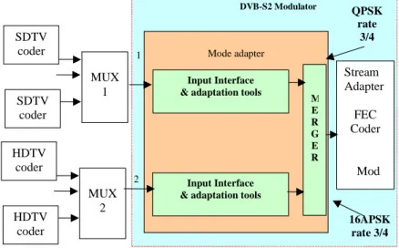
5.1 SDTV broadcasting ...39
5.2 SDTV and HDTV broadcasting with differentiated channel protection...39
5.3 Backwards Compatible services...39
5.3.1 Hierarchical modulations ...40
6 Interactive
applications...40
6.1 IP Unicast Services...41
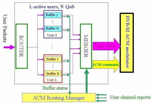
6.1.1 Single Generic Stream and ACM command ...41
6.1.2 Multiple (Generic or Transport) Streams...43
6.1.3 Encapsulation efficiency of ACM modes ...45
6.1.4 Scheduling issues...48
6.2 Independent frames structure for Packetized streams with VCM/ACM ...50
6.2.1 Independent framing issues (applicable to MPEG-TS)...50
6.2.2 Example slicing process...51
6.2.3 Specific cases...51
7
Contribution services, data content distribution/trunking and other professional applications...52
7.1 Distribution of multiple MPEG multiplexes to Digital Terrestrial TV Transmitters...52
7.2 DSNG and other professional applications ...52
7.2.1 DSNG bit rates and symbol rates...53
7.2.2 Phase noise recommendation ...53
7.2.3 Receiver filter mask ...53
7.2.5.2 DSNG Examples ...58
7.2.6 DSNG transmitting station identification ...61
7.2.7 DSNG Services using ACM ...61
Annex A:
Low Density Parity Check Codes ...63
A.1 Structure of Parity Check Matrices of Standardized LDPC Codes ...64
A.2 Description of Standardized LDPC Codes ...65
A.3 Performance
Results...66
Annex B:
DVB-S2 Physical Layer Frame and pilot structure...69
B.1
Structured PLS code for Frame Synchronization...69
B.2 Pilot
Structure...71
Annex C:
Modem algorithms design and performance over typical satellite channels...73
C.1
Modulator with Pre-Distortion ...74
C.2 Clock
Recovery ...76
C.3
Physical Layer Frame Synchronization...76
C.3.1 An algorithm for Frame Synchronization...76
C.3.2 An Alternative Frame Synchronization Algorithm ...77
C.3.2.1 Acquisition procedure description ...77
C.3.2.2 Performance Analysis ...78
C.3.2.3 Acquisition parameters optimization ...79
C.4
Carrier Frequency Recovery ...80
C.5
Automatic Gain Control ...82
C.6
Carrier Phase Recovery ...82
C.6.1 Pilot-Aided Linear Interpolation ...82
C.6.2 Fine Phase Recovery for High Order Modulations ...84
C.7 Performance
Results...84
Annex D:
Capacity assessment in ACM modes...86
D.1 System
Sizing
Issues ...87
D.2 Methodology
Description...87
D.3 Study Case Results ...88
Annex E:
Physical layer adaptation in ACM systems ...95
E.1 Channel
estimator...95
E.2
Physical Layer Selector ...97
E.2.1 Shifted Threshold ...98
E.2.2 Hysteresis ...99
E.3 Performance
results ...99
Annex F:
ACM receiver implementation ...101
F.1
Type 1 receiver...101
F.2
Type 2 receiver...102
Intellectual Property Rights
IPRs essential or potentially essential to the present document may have been declared to ETSI. The information pertaining to these essential IPRs, if any, is publicly available for ETSI members and non-members, and can be found in ETSI SR 000 314: "Intellectual Property Rights (IPRs); Essential, or potentially Essential, IPRs notified to ETSI in respect of ETSI standards", which is available from the ETSI Secretariat. Latest updates are available on the ETSI Web server (http://webapp.etsi.org/IPR/home.asp).
Pursuant to the ETSI IPR Policy, no investigation, including IPR searches, has been carried out by ETSI. No guarantee can be given as to the existence of other IPRs not referenced in ETSI SR 000 314 (or the updates on the ETSI Web server) which are, or may be, or may become, essential to the present document.
Foreword
This Technical Report (TR) has been produced by Joint Technical Committee (JTC) Broadcast of the European Broadcasting Union (EBU), Comité Européen de Normalisation ELECtrotechnique (CENELEC) and the European Telecommunications Standards Institute (ETSI).
The work of the JTC was based on the studies carried out by the European DVB Project under the auspices of the Ad Hoc Group on DVB-S2 of the DVB Technical Module. This joint group of industry, operators and broadcasters provided the necessary information on all relevant technical matters (see clause 2).
NOTE: The EBU/ETSI JTC Broadcast was established in 1990 to co-ordinate the drafting of standards in the specific field of broadcasting and related fields. Since 1995 the JTC Broadcast became a tripartite body by including in the Memorandum of Understanding also CENELEC, which is responsible for the standardization of radio and television receivers. The EBU is a professional association of broadcasting organizations whose work includes the co-ordination of its members' activities in the technical, legal, programme-making and programme-exchange domains. The EBU has active members in about 60 countries in the European broadcasting area; its headquarters is in Geneva.
European Broadcasting Union
CH-1218 GRAND SACONNEX (Geneva) Switzerland
Tel: +41 22 717 21 11 Fax: +41 22 717 24 81
Founded in September 1993, the DVB Project is a market-led consortium of public and private sector organizations in the television industry. Its aim is to establish the framework for the introduction of MPEG-2 based digital television services. Now comprising over 200 organizations from more than 25 countries around the world, DVB fosters market-led systems, which meet the real needs, and economic circumstances, of the consumer electronics and the broadcast industry.
1 Scope
The present document gives an overview of the technical and operational issues relevant to the system specified in EN 302 307 [2] "Digital Video Broadcasting (DVB): Second generation framing structure, channel coding and
modulation systems for Broadcasting, Interactive Services, News Gathering and other broadband satellite applications", including service quality and link availability evaluation for typical DSNG and fixed contribution links, with the purpose to facilitate its interpretation.
2 References
For the purposes of this Technical Report (TR), the following references apply:
[1] ETSI EN 300 421: "Digital Video Broadcasting (DVB); Framing structure, channel coding and modulation for 11/12 GHz satellite services".
[2] ETSI EN 302 307: "Digital Video Broadcasting (DVB); Second generation framing structure, channel coding and modulation systems for Broadcasting, Interactive Services, News Gathering and other broadband satellite applications".
[3] ISO/IEC 13818 (parts 1 and 2): " Information technology - Generic coding of moving pictures and associated audio information".
[4] ETSI EN 301 210: "Digital Video Broadcasting (DVB); Framing structure, channel coding and modulation for Digital Satellite News Gathering (DSNG) and other contribution applications by satellite".
[5] ETSI TR 101 154: " Digital Video Broadcasting (DVB); Implementation guidelines for the use of Video and Audio Coding in Broadcasting Applications based on the MPEG-2 Transport Stream". [6] ETSI EN 300 468: "Digital Video Broadcasting (DVB); Specification for Service Information (SI)
in DVB systems".
[7] ETSI EN 301 192: "Digital Video Broadcasting (DVB); DVB specification for data broadcasting". [8] ETSI EN 300 429: "Digital Video Broadcasting (DVB); Framing structure, channel coding and
modulation for cable systems".
[9] ETSI TR 101 221: "Digital Video Broadcasting (DVB); User guideline for Digital Satellite News Gathering (DSNG) and other contribution applications by satellite".
[10] U. Reimers, A. Morello: "DVB-S2, the second generation standard for satellite broadcasting and unicasting", International Journal on Satellite Communication Networks, 2004; 22.
[11] R. Gallager: "Low Density Parity Check Codes", IRE Trans. on Info. Theory, January 1962. [12] M. Eroz, F.-W. Sun and L.-N. Lee: "DVB-S2 Low Density Parity Check Codes with near Shannon
Limit Performance", International Journal on Satellite Communication Networks, 2004; 22. [13] E. Casini, R. De Gaudenzi, A. Ginesi: "DVB-S2 modem algorithms design and performance over
typical satellite channels", International Journal on Satellite Communication Networks, 2004; 22. [14] F.-W. Sun Y. Jiang and L.-N. Lee: "Frame synchronization and pilot structure for DVB-S2"
International Journal on Satellite Communication Networks, 2004; 22.
[15] R. Rinaldo, M. Vazquez-Castro, A. Morello: "DVB-S2 ACM modes for IP and MPEG unicast applications", International Journal on Satellite Communication Networks, 2004; 22.
[16] S. Cioni, R. De Gaudenzi, R. Rinaldo: "Adaptive Coding and Modulation for the Forward Link of Broadband Satellite Networks" in the Proc. of the Globecom 2003 Conference, San Francisco, Dec 2003.
[17] E. Chen, J. L. Koslov, V. Mignone, J. Santoru: "DVB-S2 Backward-compatible modes: a Bridge Between the Present and the Future", International Journal on Satellite Communication Networks, 2004; 22.
[18] R. Rinaldo, R. De Gaudenzi: "Capacity analysis and system optimization for the forward link of multi-beam satellite broadband systems exploiting adaptive coding and modulation", International Journal on Satellite Communication Networks, 2004; 22.
[19] U. Reimers (ed.): "Digital Video Broadcasting - The DVB Family of Standards for Digital Television", 2nd ed., 2004, Springer Publishers, New York, ISBN 3-540-43545-X. [20] M.A. Vazquez-Castro et Al.: "Scheduling issues in ACM DVB-S2 systems: performance
assessment through a comprehensive OPNET simulator", under preparation.
[21] C.E. Gilchriest: "Signal to Noise Monitoring" JPL Space Programs Summary, No 37-27, Vol IV, pp 169-176.
[22] D. J. MacKay and R. M. Neal: "Good codes based on very sparse matrices", 5th IMA Conf. 1995, pp.100-111.
[23] D. J. MacKay and R. M. Neal: "Near Shannon limit performance of low density parity check codes", Electronics Lett. Mar. 1997, vol. 33, no.6, pp. 457-458.
[24] T. Richardson and R. Urbanke: "Efficient encoding of low-density parity check codes", IEEE Trans. Info. Theory, vol. 47, pp.638-656, Feb. 2001.
[25] T. Richardson, A. Shokrollahi and R. Urbanke: "Design of capacity approaching irregular low density parity check codes", IEEE Trans. Inform. Theory, Feb. 2001, vol. 47, pp. 619-637. [26] U. Mengali and A.N. D'Andrea: "Synchronization Techniques for Digital Receivers", Plenum
Press, New York, USA, 1997.
[27] R. De Gaudenzi, A. Guillen i Fabregas, A. Martinez Vicente: "Turbo-coded APSK Modulations for Satellite Broadcasting and Multicasting- Part I: Coded Modulation Design", submitted to IEEE Trans. On Wireless Communications 2004.
[28] R. De Gaudenzi, A. Guillen i Fabregas, A. Martinez Vicente: "Turbo-coded APSK Modulations for Satellite Broadcasting - Part II: End-to-End Performance" submitted to IEEE Trans. On Wireless Communications 2004.
[29] G. Karam and H. Sari: "A Data Pre-distortion Technique with Memory for QAM Radio Systems", IEEE Transactions on Communications, Vol. COM-39, No. 2, pp 336- 344, February 1991. [30] R. De Gaudenzi and M. Luise: "Design and Analysis of an All-Digital Demodulator for Trellis
Coded 16-QAM Transmission over a Non-linear Satellite Channel", IEEE Trans. on Comm., Vol. 43, No. 2/3/4, February/March/April 1995, part I.
[31] F. M. Gardner: "A BPSK/QPSK timing-error detector for sampled receivers", IEEE Trans. On Communications, vol. COM-34, no. 5, May 1986.
[32] M. Luise and R. Reggiannini: "Carrier Frequency Recovery in All Digital Modems for Burst Mode Transmissions", IEEE Transactions on Communications, COM-43, pp. 1169-1178,
Feb./March/Apr. 1995.
[33] M. Oerder and H. Meyr: "Digital Filter and Square Timing Recovery", IEEE Trans. Commun., COM-36, May 1988.
[34] Jack K.Holmes: "Coherent spread spectrum systems", Wiley Interscience, pp 395 to 426. [35] A. Morello, V. Mignone: "DVB-S2 ready to lift-off", IBC'04 Conference, Amsterdam,
9-13 September, 2004.
[36] D.R. Pauluzzi and N.C. Beaulieu: "A Comparison of SNR Estimation Techniques for the AWGN channel", IEEE Trans. Comm., vol. 48, pp. 1681-1691, Oct. 2000.
[37] L. Castanet et al.: "Comparison of Various Methods for Combining Propagation Effects and Predicting Loss in Low-Availability Systems in the 20-50 GHz Frequency Range", Int. Journ. on Sat. Comm., Vol. 19, pp. 317-334, 2001.
[38] E. Casini: "DVB-S2 end-to-end performance with linearized and non-linearized TWT amplifiers" ESA document Ref. TEC-ETC/2004.84/EC/ec.
[39] F. J. Williams, N.J.A. Sloane: "The Theory of error correction coding", Elsevier, New York, 1977. [40] ETSI EN 300 744: "Digital Video Broadcasting (DVB); Framing structure, channel coding and
modulation for digital terrestrial television".
[41] ETSI EN 301 790: "Digital Video Broadcasting (DVB); Interaction channel for satellite distribution systems".
[42] ETSI ETS 300 801: "Digital Video Broadcasting (DVB); Interaction channel through Public Switched Telecommunications Network (PSTN)/ Integrated Services Digital Networks (ISDN)". [43] ETSI EN 301 195: "Digital Video Broadcasting (DVB); Interaction channel through the Global
System for Mobile communications (GSM)".
[44] ETSI ES 200 800: "Digital Video Broadcasting (DVB); DVB interaction channel for Cable TV distribution systems (CATV)".
[45] ITU-R Recommendation SNG.770-1: "Uniform operational procedures for satellite news gathering (SNG)".
3
Symbols and abbreviations
3.1 Symbols
For the purposes of the present document, the following symbols apply:
α Roll-off factor
BS Bandwidth of the frequency Slot allocated to a service
c codeword
C/N Carrier-to-noise power ratio (N measured in a bandwidth equal to symbol rate) C/N+I Carrier-to-(Noise + Interference) ratio
DFL Data Field Length
Eb/N0 Ratio between the energy per information bit and single sided noise power spectral density Es/N0 Ratio between the energy per transmitted symbol and single sided noise power spectral density Es/(N0 +I0) Ratio between the energy per transmitted symbol and single sided noise plus interference power
spectral density
Φ Antenna diameter
( )
LMPEG
ψ MPEG encapsulation efficiency
( )
LS DVB− 2
ψ Overall DVB-S2 encapsulation efficiency
( )
LMSη,
ψ DVB-S2 Mode and Stream adaptation efficiency
( )
ηψframing DVB-S2 Physical layer framing efficiency
i LDPC code information block
1 1
0
,
i
,...,
i
kldpc−i
LDPC code information bitsN K N
H( − )× LDPC code parity check matrix
I, Q In-phase, Quadrature phase components of the modulated signal KBCH number of bits of BCH uncoded Block
η Spectral efficiency
ηc code efficiency
ηMOD number of transmitted bits per constellation symbol
L IP packet length
m BCH code information word
m(x) BCH code message polynomial 1
1
0
,
p
,...
p
nldpc−kldpc−p
LDPC code parity bitsq code rate dependant constant for LDPC codes
θ deviation angle in hierarchical constellations
ρ roll-off
rm In-band ripple (dB)
Rs Symbol rate corresponding to the bilateral Nyquist bandwidth of the modulated signal Ru Useful bit rate at the DVB-S2 system input
S Number of Slots in a XFECFRAME
Ts Symbol period
Tloop loop delay
Tprop propagation time
Tq waiting time
UPL User Packet Length
TST Threshold on SOF in Tentative state TPT Threshold on PLSCODE in Tentative state TSL Threshold on SOF in Locked state
3.2 Abbreviations
For the purposes of the present document, the following abbreviations apply: ACM Adaptive Coding and Modulation
AGC Automatic Gain Control
AVC Advanced Video Coding
AWGN Additive White Gaussian Noise BB Baseband
BER Bit Error Ratio
BC Backwards-Compatible
NOTE: Referred to the system allowing partial stream reception by DVB-S receivers. NBC Non-Backwards-Compatible
BCH Bose-Chaudhuri-Hocquenghem multiple error correction binary block code
BS Broadcast Service
BW Bandwidth (at -3 dB) of the transponder CBR Constant Bit Rate
CCM Constant Coding and Modulation CRC Cyclic Redundancy Check
D Decimal notation
DAGC Digital AGC
DA-VT AGC Data-Aided version of the Vector-Tracker Automatic Gain Control
DD Decision Directed
DNP Deleted Null Packets
DSNG Digital Satellite News Gathering
DTH Direct To Home
DTT Digital Terrestrial Television
DTV Digital TeleVision
DVB Digital Video Broadcasting project
DVB-S DVB System for satellite broadcasting as specified in EN 300 421 DVB-S2 DVB-S2 System as specified in EN 302 307
EN European Norm
ETS European Telecommunication Standard FDM Frequency Division Multiplex
FEC Forward Error Correction FF Feedforward FIFO First In First Out
GS Generic Stream
HDTV High Definition Television
HP High Priority
HPA High Power Amplifier
IBO Input Back Off
IF Intermediate Frequency
IMUX Input MUltipleXer - Filter IRD Integrated Receiver Decoder
IS Interactive Services
ISCR Input Stream Clock Reference
ISI InterSymbol Interference
ITU International Telecommunications Union LDPC Low Density Parity Check (codes)
LG Low Gain
LNB Low Noise Block
LP Low Priority
ML Maximum Likelihood
MPEG Moving Pictures Experts Group
MPE Multi-Protocol Encapsulation
MUX Multiplex
NA Not Applicable
NCO Numerically Controlled Oscillator
NG Nominal Gain
OBO Output Back Off
OMUX Output Multiplexer - Filter
NP Null Packets
PER (MPEG TS) Packet Error Rate
PID Packet Identifier
PFA Probability of False Alarm PND Probability of Non Detection
PL Physical Layer
PLL Phase-Locked Loop
PLS Physical Layer Signalling
PLSCODE PLS code
PS Professional Services
PSD Power Spectral Density
PSK Phase Shift Keying
QEF Quasi-Error-Free QoS Quality of Service
QPSK Quaternary Phase Shift Keying
RF Radio Frequency
r.m.s. root mean square RX Receiver
RR Round Robin
SDTV Standard Definition Television SNG Satellite News Gathering SNR Signal to Noise Power Ratio SMATV Satellite Master Antenna TeleVision
SOF Start of Frame
SRRC Square Root Raised Cosine Filter TDM Time Division Multiplex
TS Transport Stream
TV Television TX Transmitter
VCM Variable Coding and Modulation
16APSK 16-ary Amplitude and Phase Shift Keying 32APSK 32-ary Amplitude and Phase Shift Keying 8PSK 8-ary Phase Shift Keying
4
General description of the technical characteristics of
the DVB-S2 system
DVB-S2 is the second-generation DVB specification for broadband satellite applications, developed on the success of the first generation specifications, DVB-S for broadcasting and DVB-DSNG for satellite news gathering and
contribution services, benefiting from the technological achievements of the last decade. It has been designed for:
• Broadcast Services for standard definition TV and HDTV.
• Interactive Services including Internet Access for consumer applications.
• Professional Applications, such as Digital TV contribution and News Gathering, TV distribution to terrestrial VHF/UHF transmitters, Data Content distribution and Internet Trunking.
The DVB-S2 standard has been specified around three key concepts: best transmission performance, total flexibility and reasonable receiver complexity.
To achieve the best performance-complexity trade-off, DVB-S2 benefits from more recent developments in channel coding (adoption of LDPC codes) and modulation (use of QPSK, 8PSK, 16APSK and 32APSK). The result is typically a 30 % capacity increase over DVB-S under the same transmission conditions. In addition, for broadcast applications, DVB-S2 is not constrained to the use of QPSK and therefore it can deliver significantly higher bit rates over high power satellites, thus still increasing capacity gain with respect to DVB-S. Furthermore, when used for interactive point-to-point applications like IP unicasting, the gain of DVB-S2 over DVB-S is even greater: Variable Coding and Modulation (VCM) functionality allows different modulations and error protection levels to be used and changed on a
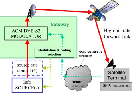
frame-by-frame basis. This may be combined with the use of a return channel to achieve closed-loop Adaptive Coding and Modulation (ACM), thus allowing the transmission parameters to be optimized for each individual user, dependant on its own link conditions.
DVB-S2 is so flexible that it can cope with any existing satellite transponder characteristics, with a large variety of spectrum efficiencies and associated C/N requirements. Furthermore, it is not limited to MPEG-2 video and audio source coding, but it is designed to handle a variety of audio-video and data formats including formats which the DVB Project is currently defining for future applications. DVB-S2 accommodates any input stream format, including continuous bit-streams, single or multiple MPEG Transport Streams, IP as well as ATM packets. This future proofing will allow other current and future data schemes to be used without the need for a new specification.
It is based on the "tool-kit" approach that allows to cover all the application areas while still keeping the single-chip decoder at reasonable complexity levels, thus enabling the use of mass market products also for professional applications.
Backwards compatible modes are available, allowing existing DVB-S services and set-top-boxes to continue working during any transitional period. When there is no problem of legacy receivers, NBC modes offer the full benefits of DVB-S2.
4.1 Commercial
requirements
(Extracted from doc. DVB-BSS17rev1 "Advanced Coding and Modulation Schemes for Broadband Satellite Services - Commercial Requirements").
The DVB-S standard was developed primarily with unidirectional broadcast applications in mind, but has been adopted for other purposes, such as point-to-point data transmission. One of the reasons for this is the availability of inexpensive receive silicon as a result of the high volume broadcast receiver market. The Commercial Module of DVB (DVB-CM) foresaw a similar process for the new system, where the volume driver is expected to remain broadcast applications.
To avoid confusion in the distinction between broadcast and non-broadcast applications, with increasing provision of entertainment services over IP networks, and increasing use of interactivity with TV, DVB-CM introduced the following definitions:
• Broadcast services are defined as TV, radio and associated data (e.g. teletext, EPG, etc.) in contribution (e.g. DSNG), distribution (e.g. SMATV and cable feeds) and direct to home applications. In the case of interactive services, it is intended only the forward path.
• Non-broadcast services are defined as point-to-point and point-to-multipoint data services.
4.1.1
Commercial Requirements for Broadcast Services
Broadcast services are characterized by having a large coverage area and providing audio-visual and data services to an extensive base of similar reception systems (both antennas and receivers) with a high degree of availability. For broadcasters there are various reasons to use higher order modulation and/or advanced coding schemes, including:
• Increased data throughput in a given bandwidth.
• Increased availability through improved link margin.
• Increased coverage area.
A key factor for many established broadcasters is the issue of backwards-compatibility. Large populations of DVB-S receivers in the field must continue to provide service to customers for at least several years. This is particularly important where there is a subsidy. Backwards-compatible modulation systems that allow DVB-S receivers to continue operating, while providing additional capacity and services to new, advanced receivers, are seen as the only
commercially viable way forward for some operators. Backwards-compatible systems however suffer from two disadvantages:
• Compatibility will cause the overall performance to fall short of that achievable by non backwards-compatible systems.
• There will be some performance penalty in the behaviour of existing QPSK receivers. Note that some operators are reluctant to accept even a slight performance penalty, as this increases service call-outs and churn.
On the basis of the above considerations, DVB-CM concluded that the technical specification should provide for two approaches:
• A non backwards-compatible scheme, intended for use in systems requiring the highest efficiency, and not requiring that transmissions should be receivable by existing receiver populations.
• A backwards-compatible scheme that can be received by existing receiver populations, but provides additional capacity to enhanced receivers. This should have the capability of migrating to a more efficient non
backwards-compatible mode once all DVB-S receivers have been replaced. Furthermore the technical specification should also take into account the following:
• A bit-rate increase of at least 35 % over DVB-S should be achieved.
• Service availability targets remain no more than one uncorrected error per hour.
• For DVB-S2 backwards-compatible transmissions, there should be no requirement for any change to existing DVB-S receivers, including the antenna and LNB. This assumes continued use of the same transponder.
• For DVB-S2 non backwards-compatible transmissions, reliable reception should be possible using receive antenna diameters in the range 0,4 m to 0,8 m. Due account shall be taken of anticipated satellite system characteristics (e.g. power, bandwidth, interference) over the next ten years.
• While the technical specification is concerned with the transmission format, it is important that this does not impose an undue burden on receiver costs. New receiver silicon, enabling multi-mode reception, including DVB-S, backwards and non-backwards compatible DVB-S2, in volume should cost no more than 15 % more
4.1.2
Commercial Requirements for Non-Broadcast Services
In general, DVB-CM stated that characteristics that are desirable exclusively for non-broadcast services should only be included in the base specification if the burden of cost to the broadcast receiver is negligible. The specification should be available for consideration as an alternative forward path for DVB-RCS Ku- and Ka-band systems and other data systems currently using DVB-S. In the future non-broadcast two-way services will need to take advantage of such techniques as adaptive modulation, adaptive coding and adaptive power systems. The services provided will include:
• Point-to-point services (e.g. IP-backbone).
• Point-to-multipoint services (e.g. VPN services).
• Two way mass market services (e.g. Internet access via satellite).
The above services are differentiated from broadcast services by the following requirements and characteristics:
• The possibility of targeting particular receivers with particular content within the common transport system. It is therefore not necessary to be able to decode the entire data stream at a typical user terminal.
• The possibility of establishing different quality of service targets for services to different customers in different areas.
• Receiver network volumes may not be as high as broadcast applications, but could benefit from inexpensive silicon arising from broadcast applications.
• Satellite capacity is generally the most expensive part of a link, always more expensive compared to the equipment behind it.
• Business users may be able to accept significantly larger receive antennas that residential users. In such cases it would be desirable to use this to allow greater user data rates to be transmitted.
The technical specifications shall additionally take into account the following requirements:
• Non-broadcast services should be receivable on antennas down to typical consumer sizes.
• A wide range of system parameters should be available to address applications across consumer to business antenna sizes, and telecom to broadcast satellite powers.
• As in the case of broadcast applications, it should be possible to manufacture low cost receivers. If the impact of advanced features such as adaptive coding and modulation that are not relevant to broadcast applications is to raise broadcast receiver costs excessively, then these features could exist in an enhanced profile, available as an option.
• The technology shall aim to optimize the use of the transponder (keeping all other technical parameters the same, a minimum capacity increase of 100 % shall be targeted for the professional, non-broadcast market case using adaptive technologies).
• The target BER shall be at least as good as for broadcast applications.
4.1.3
Common Commercial Requirements
The primary goal of new broadband satellite systems is to deliver a significantly higher net data rate in a given transponder bandwidth than the current DVB-S standard. Technical specifications for such a new standard shall not prevent operators from taking into account all issues covered by local, national, and international laws, especially those related to security (protection of personal data, encryption of data and services). The new specification will cover transmit-end functions only, but take into account the consequent cost of receive silicon. The market will determine what features are actually implemented in receive silicon. For the protection of existing business, the current DVB-S standard shall not be modified, nor shall changes to other standards cause any existing feature to become invalid. The new specification will contain a form of modulation and coding that is compatible with existing DVB-S receivers ("backwards compatible"), and if it offers greater efficiency, a non-backwards compatible form also. The new specification will contain a range of options for coding that are appropriate to a wide range of applications. The new specifications must be application neutral and media content independent. The specifications must be transmission frequency neutral, or contain the elements allowing for an adaptation to the specifics of certain frequency ranges (e.g. Ka Band). Specifications for broadcast and non-broadcast applications shall be provided by the definition of a limited number of profiles. The specification shall not prevent the use of any kind of scrambling and security system at the transport layer.
4.2 Application
scenarios
The DVB-S2 system has been optimized for the following broadband satellite application scenarios.
• Broadcast Services (BS): digital multi-programme Television (TV)/High Definition Television (HDTV) broadcasting services.
DVB-S2 is intended to provide Direct-To-Home (DTH) services for consumer Integrated Receiver Decoder (IRD), as well as collective antenna systems (Satellite Master Antenna Television - SMATV) and cable television head-end stations (possibly with remodulation, see [8]). DVB-S2 may be considered a successor to the current DVB-S standard [1], and may be introduced for new services and allow for a long-term migration. BS services are transported in MPEG Transport Stream format. VCM may be applied on multiple transport stream to achieve a differentiated error protection for different services (TV, HDTV, audio, multimedia). Two modes are available:
- Non Backwards Compatible Broadcast Services (NBC-BS), not backwards-compatible with [1]. - Backwards-Compatible Broadcast Services (BC-BS), backwards-compatible with [1].
In fact, with a large number of DVB-S receivers already installed, backwards compatibility may be required for a period of time, where old receivers continue to receive the same capacity as before, while the new DVB-S2 receivers could receive additional capacity broadcasts. When the complete receiver population has migrated to DVB-S2, the transmitted signal can be modified to a non-backward compatible mode, thus exploiting the full potential of DVB-S2. To facilitate the reception of DVB-S services by DVB-S2 receivers, implementation of DVB-S in DVB-S2 chips is highly recommended.
• Interactive Services (IS): interactive data services including internet access
DVB-S2 is intended to provide interactive services to consumer IRDs and to personal computers, where DVB-S2's forward path supersedes the current DVB-S standard [1] for interactive systems. No
recommendation is included in the DVB-S and DVB-S2 standards as far as the return path is concerned. Therefore, interactivity can be established either via terrestrial connection through telephone lines, or via satellite. DVB offers a variety of return link specifications, such as for example DVB-RCS (EN 301 790 [41]), DVB-RCP (ETS 300 801 [42]), DVB-RCG (EN 301 195 [43]), DVB-RCC (ES 200 800 [44]). Data services are transported in (single or multiple) Transport Stream format according to [7] (e.g. using Multiprotocol Encapsulation), or in (single or multiple) generic stream format. DVB-S2 can provide Constant Coding and Modulation (CCM), or Adaptive Coding and Modulation (ACM), where each individual satellite receiving station controls the protection mode of the traffic addressed to it.
• Digital TV Contribution and Satellite News Gathering (DTVC/DSNG)
Digital television contribution applications by satellite consist of point-to-point or point-to-multipoint transmissions, connecting fixed or transportable uplink and receiving stations. They are not intended for reception by the general public. According to ITU-R Recommendation SNG.770-1 [45], SNG is defined as "Temporary and occasional transmission with short notice of television or sound for broadcasting purposes, using highly portable or transportable uplink earth stations, etc.". Services are transported in single (or multiple) MPEG Transport Stream format. DVB-S2 can provide Constant Coding and Modulation (CCM), or Adaptive Coding and Modulation (ACM). In this latter case, a single satellite receiving station typically controls the protection mode of the full multiplex.
• Data content distribution/trunking and other professional applications (PS)
These services are mainly point-to-point or point-to-multipoint, including interactive services to professional head-ends, which re-distribute services over other media. Services may be transported in (single or multiple) generic stream format. The system can provide Constant Coding and Modulation (CCM), Variable Coding and Modulation (VCM) or Adaptive Coding and Modulation (ACM). In this latter case, a single satellite receiving station typically controls the protection mode of the full TDM multiplex, or multiple receiving stations control the protection mode of the traffic addressed to each one. In either case, interactive or non-interactive, the present document is only concerned with the forward broadband channel.
For all these applications, DVB-S2 benefits from more recent developments in channel coding and modulation, achieving typically a 30 % capacity increase over DVB-S [1]. When used for point-to-point applications like IP
unicasting or DSNG, the gain of DVB-S2 is even greater. Adaptive Coding and Modulation (ACM) functionality allows different modulation formats and error protection levels (i.e. coding rates) to be used and changed on a frame-by-frame basis within the transmitted data stream. By means of a return channel, informing the transmitter of the actual receiving condition, the transmission parameters may be optimized for each individual user, dependant on path conditions. Furthermore DVB-S2 is compatible with Moving Pictures Experts Group (MPEG-2 and MPEG-4) coded TV
services [3], with a Transport Stream packet multiplex. Multiplex flexibility allows the use of the transmission capacity for a variety of TV service configurations, including sound and data services. All service components are Time Division Multiplexed (TDM) on a single digital carrier.
4.3 System
architecture
To achieve the best performance, DVB-S2 is based on LDPC (Low Density Parity Check) codes, simple block codes with very limited algebraic structure, discovered by R. Gallager in 1962 [11]. LDPC codes have an easily parallelizable decoding algorithm which consists of simple operations such as addition, comparison and table look-up [22], [23]; moreover the degree of parallelism is "adjustable" which makes it easy to trade-off throughput and complexity (see note 1).
NOTE 1: The maximum decoder complexity was set to correspond to 14 mm2 of silicon using a 0,13 µm technology, and the reference symbol rate was 55 Mbaud.
Their key characteristics, allowing quasi-error free operation at only 0,6 to 1,2 dB from the Shannon limit [12], are:
• the very large LDPC code block length (64 800 bits for the normal frame, and 16 200 bits for the short frame);
• the large number of decoding iterations (around 50 SISO iterations);
• the presence of a concatenated BCH outer code (without any interleaver), defined by the designers as a "cheap insurance against unwanted error floors at high C/N ratios".
In comparison, the DVB-S and DVB-DSNG soft-decision Viterbi decoder takes decisions on blocks of only 100 symbols, without iterations, and the RS code over blocks of about 1 600 bits (interleaving factor 12), offering already quite good performance (see figure 3), around 3 dB from the Shannon limit.
Digital transmissions via satellite are affected by power and bandwidth limitations. Therefore DVB-S2 provides for many transmission modes (FEC coding and modulations), giving different trade-offs between power and spectrum efficiency. Code rates of 1/4, 1/3, 2/5, 1/2, 3/5, 2/3, 3/4, 4/5, 5/6, 8/9 and 9/10 are available depending on the selected modulation and the system requirements. Coding rates 1/4, 1/3 and 2/5 have been introduced to operate, in combination with QPSK, under exceptionally poor link conditions, where the signal level is below the noise level. Computer simulations demonstrated the superiority of such modes over BPSK modulation combined with code rates 1/2, 2/3 and 4/5. The introduction of two FEC code block length (64 800 and 16 200) was dictated by two opposite needs: the C/N performance improves for long block lengths, but the end-to-end modem latency increases as well. Therefore for applications not critical for delays (such as for example broadcasting) the long frames are the best solution, while for interactive applications a shorter frame may be more efficient when a short information packet has to be forwarded immediately by the transmitting station. Four modulation modes can be selected for the transmitted payload (see figure 1). text 1100 1101 1111 1110 0000 0100 0101 0001 1001 1011 0011 0111 0110 0010 1010 1000 I Q LSB MSB R1 R2 text 10001 10011 10111 10101 00000 10000 10010 00010 00011 00111 00110 10110 10100 00100 00101 00001 I Q R1 R2 R3 11000 01000 11001 01001 01101 11101 01100 11100 11110 01110 11111 01111 01011 11011 01010 11010 (c) 16APSK (d) 32APSK 00 I Q ρ= ρ=ρ= ρ= 10 11 01 Q=LSB I=MSB 000 I Q ρ=1 ρ=1 ρ=1 ρ=1 011 111 001 101 010 110 100 φ=π/4 φ=π/4 φ=π/4 φ=π/4 (a) QPSK (b) 8PSK
Figure 1: The four possible DVB-S2 constellations before physical layer scrambling QPSK and 8PSK are typically proposed for broadcast applications, since they are virtually constant envelope
modulations and can be used in non-linear satellite transponders driven near saturation. For some specific broadcasting applications (i.e. regional spot beams) and interactive application operating with multi-beam satellites, 16APSK provides extra spectral efficiency with very limited linearity requirements if proper pre-distortion schemes are employed. 32APSK modes, mainly targeted to professional applications, can also be used for broadcasting, but these require a higher level of available C/N and the adoption of advanced pre-distortion methods in the up-link station to minimize the effect of transponder non-linearity. Whilst these modes are not as power efficient as the other modes, the data throughput is much greater. 16APSK and 32APSK constellations have been optimized to operate over a non-linear transponder by placing the points on circles. Nevertheless their performances on a linear channel are comparable with those of 16QAM and 32QAM respectively. All the modes are also appropriate for operation in quasi-linear satellite channels, in multi-carrier Frequency Division Multiplex (FDM) type applications.
By selecting the modulation constellation and code rates, spectrum efficiencies from 0,5 to 4,5 bit/second/Hz are available and can be chosen dependant on the capabilities and restrictions of the satellite transponder used.
DVB-S2 also features the presence of a Physical Layer (PL) scrambler that is X-oring the I-Q modulator symbols (inclusive of the optional pilot symbols but excluding the PL header) with a complex binary randomization sequence of length truncated to the current PLFRAME duration. The complex randomization sequence has an original period of 262 143 symbols and is the one used in the terrestrial UMTS standard. It provides good auto and cross-correlation properties and allows to simply generate up to 262 142 distinct complex sequences. The main advantages of the physical layer randomization presence in DVB-S2 are:
• capability to uniquely "sign" individual carriers present in a multi-carrier multi channel transponder;
• randomization of periodic pilot symbols pattern when pilot is time interleaved in the carrier;
• randomization of other satellite or same satellite other beams interference. It should be remarked that in case of interfering signals with lower baud rate than the useful carrier the physical layer descrambling present in the DVB-S2 demodulator will make interferer appearing as wideband interference thus reducing their degradation effect;
• the physical layer randomization also allows the application of repetition coding at the DVB-S2 modulator to further increase the C/(N+I) operating range of the system.
DVB-S2 has three roll-off factor choices to determine spectrum shape. These are α=0,35 as in DVB-S and two others, namely α=0,25, α=0,20 for tighter bandwidth shape restriction.
DVB-S2 is suitable for use on different satellite transponder bandwidths and frequency bands. The symbol rate is matched to given transponder characteristics, and, in the case of multiple carriers per transponder (FDM), to the frequency plan adopted.
Two levels of framing structures have been designed:
• the first at physical level, carrying few highly-protected signalling bits;
• the second at base-band level, carrying a variety of signalling bits, to allow the maximum flexibility on the input signal adaptation.
Physical Level framing
The first level of framing structure has been designed to provide robust synchronization and signalling at physical layer [14]. Thus a receiver may synchronize (carrier and phase recovery, frame synchronization) and detect the modulation and coding parameters before demodulation and FEC decoding. The DVB-S2 physical layer "train" is composed of a regular sequence of periodic "wagons" (physical layer frames, PL Frame): within a wagon, the modulation and coding scheme is homogeneous, but may change (Variable Coding and Modulation) in adjacent wagons. The PL framing structure is application independent (Constant Coding and Modulation or Variable Coding and Modulation).
Every PL Frame is composed of:
• a payload of 64 800 bits (normal FEC frame) or 16 200 bits (short FEC frame), generated by encoding the user bits according to the selected FEC scheme; thus the payload corresponds to a code block of the concatenated LDPC/BCH FEC;
• a PL Header, containing synchronization and signalling information: type of modulation and FEC rate, frame length, presence/absence of pilot symbols to facilitate synchronization.
The PL-Header is always composed of 90 symbols (using a fixed Π/2 binary modulation), and the payload is always composed of an integer multiple of 90 symbols (excluding pilot symbols). Since the PL Header is the first entity to be decoded by the receiver, it could not be protected by the powerful LDPC/BCH FEC scheme. On the other hand, it had to be perfectly decodable under the worst-case link conditions. Therefore designers selected a very low-rate 7/64 block code, suitable for soft-decision correlation decoding, and minimized the number of signalling bits to reduce decoding complexity and global efficiency loss. For example, assuming a 64 800 bit frame, the worst case efficiency of the PL Frame is 99,3 % (excluding pilot symbols).
Base-band Level framing
Another level of framing structure, the "baseband frame", allows a more complete signalling functionality to configure the receiver according to the application scenarios: single or multiple input streams, generic or transport stream, CCM (Constant Coding and Modulation) or ACM (Adaptive Coding and Modulation). Thanks to the LDPC/BCH protection and the wide length of the FEC frame, the Baseband (BB) Header may contain many signalling bits (80) without loosing neither transmission efficiency nor ruggedness against noise.
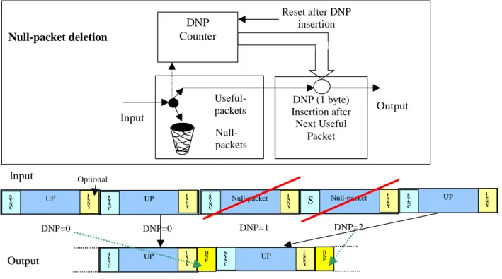
This BB-Header carries other important signalling information, such as: labelling the modulator input streams, describing the position and characteristics of user packets, indicating the presence of padding bits in the transmitted "baseband frame", signalling the activation of specific tools (Null-packet deletion function, Input Stream
Synchronization function, as described in [14]), signalling the adopted modulation roll-off (see note 2).
NOTE 2: The roll-off factor needs not be signalled at physical layer, since (sub-optimum) reception is possible even assuming unknown roll-off.
4.3.1
The system block diagram
The DVB-S2 System is composed of a sequence of functional blocks as described in figure 2.
The block identified as "Mode Adaptation" is application dependent. Input sequences may be single or multiple Transport Streams (TS), single or multiple Generic Streams (packetized or continuous): the block provides input stream interfacing, optional tools required for ACM (e.g. synchronization (see note 1) and null-packet deletion for Transport Streams (see note 2), described in clause 4.5.2.1), CRC coding (and replacement of SYNC bytes) for error detection in the receiver for packetized input streams. Furthermore, for multiple inputs, it provides merging of input streams in a single transmission signal and slicing in FEC code blocks, Data Fields. These latter are composed of DFL bits, where KBCH -80 ≥ DFL ≥0, taken from a single input port, to be transmitted in a homogeneous transmission mode (FEC code and modulation). KBCH is the BCH uncoded block length, which is dependent on the FECFRAME length (normal or short) and on the coding rate, and 80 bits is the BBHEADER length. The Base-Band Header is appended in front of the Data Field, to notify the receiver of the input stream format and Mode Adaptation type.
NOTE 1: Data processing in DVB-S2 may produce variable transmission delay. This block allows to guarantee constant-bit-rate and constant end-to-end transmission delay for packetized input stream [15]. NOTE 2: To reduce the information rate and increase the error protection in the modulator. The process allows
null-packets re-insertion in the receiver in the exact place where they originally were [15].
BBFRAME FECFRAME PLFRAME
FEC ENCODING PL FRAMING MODULATION
BCH Encoder (NBCH,KBCH) PL Signalling & Pilot insertion LDPC Encoder (nldpc,kldpc) BB Filter and Quadrature Modulation Bit mapper into constel-lations I Q QPSK, 8PSK, 16APSK, 32APSK rates 1/4,1/3,2/5 1/2, 3/5, 2/3, 3/4, 4/5, 5/6, 8/9, 9/10 α αα α=0,35, 0,25, 0,20 to the RF satellite channel MAPPING BB SCRAM BLER STREAM ADAPTATION PADDER BB Signalling Merger Slicer MODE ADAPTATION PL SCRAM BLER Single Input Stream Multiple Input Streams BBHEADER DATAFIELD Bit Inter-leaver Dummy PLFRAME Insertion Null-packet Deletion (ACM, TS) CRC-8 Encoder Input Stream Synchroniser Input interface Null-packet Deletion (ACM, TS) Input Stream Synchroniser Input interface DATA ACM COMMAND
Dotted sub-systems are not relevant for single transport stream broadcasting applications CRC-8 Encoder LP stream for BC modes Buffer Buffer
In case the user data available for transmission are not sufficient to completely fill a BBFRAME, padding is provided by the "Stream Adaptation" block to complete it. Base-band scrambling is also provided.
"FEC Encoding" carries out the concatenation of BCH outer code and LDPC inner codes. Depending on the application area, the FEC coded blocks (FEC frames) can have length 64 800 (normal frame) or 16 200 (short frame) bits. When VCM or ACM are used, FEC and modulation mode are constant within a frame but may be changed in different frames; furthermore, the transmitted signal can contain a mix of normal and short code blocks. Bit interleaving is then applied to FEC coded bits for 8PSK, 16APSK and 32APSK to separate bits mapped onto the same transmission signal.
"Mapping" into QPSK, 8PSK, 16APSK and 32APSK constellations is then applied to get a complex XFECFRAME, composed of 64 800/ηMOD or 16 200/ηMOD modulated symbols (ηMOD being the number of bits carried by a constellation symbol).
"Physical Layer Framing", synchronous with the FEC frames, provides optional dummy PL frame insertion (when no useful data is ready to be sent on the channel), PL header and optional pilot symbols insertion (2,4 % capacity loss) and scrambling for energy dispersal. Pilot symbols insertion occurs at regular intervals (36 pilot symbols each 1 440 data symbols), starting after each PLHEADER. This allows achieving the high channel estimation accuracy indicated by the standard and needed to track channel variation when ACM is utilized. The modulated symbols are inserted in a regular physical layer frame structure, composed of fixed length slots of 90 symbols. As the XFECFRAME length is dependent on both the frame type (short or normal) and the modulation order, it occupies a variable integer number of slots, which is larger the lower is the modulation order (see table 11 in [2]). The PLFRAME is obtained by adding the PLHEADER, which occupies one extra slot and carries the information related to the frame type and to the physical layer mode. After decoding the PLHEADER, the receiver can derive, through the knowledge of the transmission parameters, the current frame length and thus the start of the following frame, even if the status of the channel does not allow for successful data decoding in the current frame.
Finally, "Modulation" applies Base-Band Filtering and Quadrature Modulation, to shape the signal spectrum and to generate the RF signal. Square-root raised cosine filtering is used at the transmit side, with choice on three roll-off factors: 0,35, 0,25 and0,20.
4.3.2 Reference
performance
The DVB-S2 system may be used in "single carrier per transponder" or in "multi-carriers per transponder" (FDM) configurations. In single carrier per transponder configurations, the transmission symbol rate Rs can be matched to given transponder bandwidth BW (at -3 dB), to achieve the maximum transmission capacity compatible with the acceptable signal degradation due to transponder bandwidth limitations. To take into account possible thermal and ageing instabilities, reference can be made to the frequency response mask of the transponder. Group delay equalization at the transmitter may be used to increase the transmission capacity or to reduce degradation.
In the multi-carrier FDM configuration, Rs can be matched to the frequency slot BS allocated to the service by the frequency plan, to optimize the transmission capacity while keeping the mutual interference between adjacent carriers at an acceptable level.
4.3.2.1
Single carrier per transponder configuration
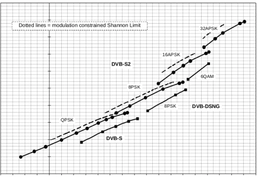
Dependant on the selected code rate and modulation constellation the system can operate at carrier to noise ratios from -2,4 dB using QPSK 1/4 to 16 dB using 32APSK 9/10 (assuming AWGN channel and ideal demodulator) (figure 3). These results have been obtained by computer simulations for a Packet Error Rate of 10-7, both for DVB-S2 and
DVB-S/DVB-DSNG, and correspond about to one erroneous Transport Stream Packet per transmission hour in a 5 Mbit/s video service (see note 1).
NOTE 1: It should be noted that this definition is slightly different from the Quasi Error Free target adopted in EN 300 421 [1]. Furthermore modem implementation margins reported in [1] and [4] are not included in figure 3.
On AWGN, the result is typically a 20 %to 35 % capacity increase over DVB-S and DVB-DSNG under the same transmission conditions and 2 dB to 2,5 dB more robust reception for the same spectrum efficiency.
0 0,5 1 1,5 2 2,5 3 3,5 4 4,5 5 -4 -3 -2 -1 0 1 2 3 4 5 6 7 8 9 10 11 12 13 14 15 16 17 C/N [dB] in BW=Rs R u [ M bi t/ se c ] pe r uni t Sy m b o l r a te R s DVB-S2 DVB-DSNG QPSK 8PSK 16APSK 32APSK DVB-S 8PSK 6QAM
Dotted lines = modulation constrained Shannon Limit
Figure 3: Required C/N versus spectrum efficiency, obtained by computer simulations on the AWGN channel (ideal demodulation) (C/N refers to average power)
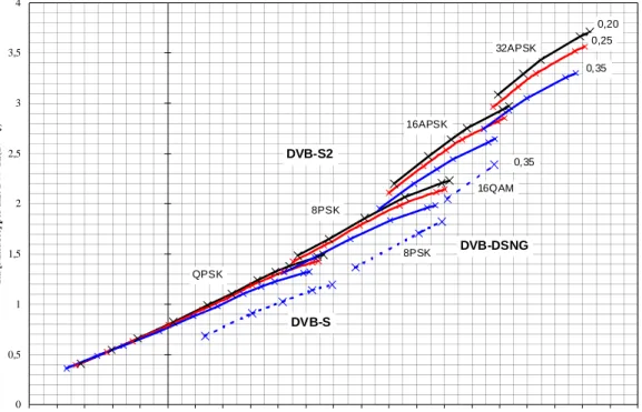
Figure 4 shows instead the DVB-S2 performance for constant satellite bandwidth BW = Rs(1+ρ) on the AWGN channel assuming ideal demodulation. The figure does not take into account the performance degradation which is expected on the satellite channel due to the signal envelope, which increases with decreasing roll-off. For DVB-DSNG only the normative roll-off 0,35 is considered, even if DVB-DSNG also includes, optionally, 0,25.
0 0,5 1 1,5 2 2,5 3 3,5 4 -5 -4 -3 -2 -1 0 1 2 3 4 5 6 7 8 9 10 11 12 13 14 15 16 17 C/N [dB] in BW=Rs(1+ρρρρ) Ru [ M b it /sec] p er u n it B W = R s( 1 + ◊ ) 0,20 0,25 0,35 DVB-S2 0,35 DVB-S DVB-DSNG QPSK 8PSK 16APSK 32APSK 8PSK 16QAM
Figure 4: Required C/N versus spectrum efficiency for constant satellite bandwidth BW = Rs(1+ρρρρ) on
the AWGN channel (ideal demodulation) (C/N refers to average power)
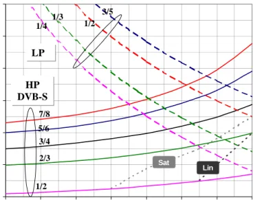
Figure 5 gives examples of the useful bit rate capacity Ru achievable by the system versus the LDPC code rate, assuming unit symbol rate RS. The symbol rate RS corresponds to the -3 dB bandwidth of the modulated signal.
RS(1+α) corresponds to the theoretical total signal bandwidth after the modulator, with α representing the roll-off factor of the modulation. The figures refer to Constant Coding and Modulation, normal FEC frame length (64 800 bits), no padding field, no pilots (the pilots would reduce the efficiency by about 2,4 %). Typical BW/RS or BS/RS ratio is 1+α = 1,35: this choice allows to obtain a negligible ES/No degradation due to transponder bandwidth limitations, and also to adjacent channel interference on a linear channel. The use of the narrower roll-off α = 0,25 and α = 0,20 may allow a transmission capacity increase but may also produce larger non-linear degradations by satellite for single carrier operation. BW/RS factors less than 1+α may also be adopted, but careful studies should be carried-out on a
0,0 0,5 1,0 1,5 2,0 2,5 3,0 3,5 4,0 4,5 0,2 0,3 0,4 0,5 0,6 0,7 0,8 0,9 LDPC code rate RU QPSK 8PSK 32APSK 1/4 1/3 2/5 1/2 3/5 2/3 3/4 4/5 5/6 8/9 16APSK 9/10
Figure 5: examples of useful bit rates RU versus LDPC code rate per unit symbol rate RS
When DVB-S2 is transmitted by satellite, quasi-constant envelope modulations, such as QPSK and 8PSK, are power efficient in single carrier per transponder configuration, since they can operate on transponders driven near saturation. 16APSK and 32APSK, which are inherently more sensitive to non-linear distortions and would require quasi-linear transponders (i.e. with larger Output-Back-Off, OBO) may be greatly improved in terms of power efficiency by using non-linear compensation techniques in the up-link station [13]. In FDM configurations, where multiple carriers occupy the same transponder, this latter must be kept in the quasi-linear operating region (i.e. with large OBO) to avoid excessive inter-modulation interference between signals. In this case the AWGN performance figures may be adopted for link budget computations.
Table 1 shows, for the single carrier per transponder configuration, the simulated C/N degradation using the satellite channel models and phase noise mask given in [2] (non linearized TWTA, IMUX and OMUX filters, phase noise relevant to consumer LNBs), at the optimum operating TWTA point (see note 2). CSAT is the un-modulated carrier power at HPA saturation, OBO is the measured power ratio (dB) between the un-modulated carrier at saturation and the modulated carrier (after OMUX). Phase noise degradation figures refer to a pilot-based carrier recovery system [13].
The figuresshow the large advantage offered by the use of dynamic pre-distortion for 16APSK and 32APSK. The large phase noise degradations quoted for APSK, and in particular for 32APSK, can be considered as pessimistic, since they refer to consumer-type LNBs, while for professional applications better front-ends may be adopted at negligible additional cost.
NOTE 2: The following parameters have been simulated [13]: Rs = 27,5 Mbaud, roll-off = 30 % (not available in DVB-S2, but giving performance between roll-off 0,35 and 0,25).
Table 1: CSAT/N loss [dB] on the satellite channel
(simulation results, Single Carrier per Transponder, optimum TWTA operating point)
Transmission Mode
CSAT/N loss [dB] without predistortion without Phase Noise
CSAT/N loss [dB] with dynamic predistortion
without Phase Noise
CSAT/N loss [dB] with dynamic predistortion
with Phase Noise
QPSK 1/2 0,62 (IBO = 0; OBO = 0,33) 0,5 (IBO = 0 dB; OBO = 0,38) 0,63 8PSK 2/3 0,95 (IBO = 0,5; OBO = 0,35) 0,6 (IBO = 0;OBO = 0,42) 0,85 16APSK 3/4 3,2 (IBO = 5; OBO = 1,7) 1,5 (IBO = 1; OBO = 1,1) 1,8 32APSK 4/5 6,2 (IBO = 9; OBO = 3,7) 2,8 (IBO = 3,6; OBO = 2,0) 3,5
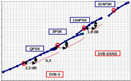
0,0 0,5 1,0 1,5 2,0 2,5 3,0 3,5 4,0 4,5 -2 -1 0 1 2 3 4 5 6 7 8 9 10 11 12 13 14 15 16 17 18 19 20 C/N [dB] in Rs Ru [b it /s ] p e r u n it R s QPSK 8PSK 16APSK 32APSK DVB-S DVB-DSNG 2,2 dB 0,3 1,9 dB
Figure 6: Examples of RU versus required C/N by satellite,
in single carrier per transponder configuration
Figure 6 shows, in the C/N - Spectral Efficiency plane, the overall performance of DVB-S2 by satellite, compared to DVB-S and DVB-DSNG (see note 3). The C/N gain of DVB-S2 versus DVB-S and DVB-DSNG, at a given spectral efficiency, remains substantially constant around 2 dB to 2,5 dB, confirming the results on AWGN. Similarly, the capacity gain at a given available C/N confirms to be in the range 0,3 to 0,4 bit/s/Hz (2,6 % pilot symbol loss is not indicated, since pilots are optional). Compared to AWGN simulations, satellite simulation curves for 16APSK and 32APSK are more aligned with QPSK and 8PSK curves, due to the amplitude limitation of the non-linear TWTA characteristics.
NOTE 3: The transmission modes indicated by circles are fully simulated [13], while the other configurations are extrapolated. The degradations of table 1are added tothe AWGN simulated figures, for the relevant constellation order, neglecting the effect of coding rates on degradations; M-QAM degradations is assimilated to M-APSK.
4.3.2.1.1
Sensitivity to satellite power amplifier characteristics
The sensitivity to different satellite power amplifiers has been investigated by means of software simulations [38]. The same channel model and phase noise mask as in [2] has been used. Three different amplifiers have been considered: the two models defined in [2], linearized TWTA (LTWTA) and non-linearized TWTA (NL-TWTA), and a second
linearized-TWTA (LTWTA2), whose characteristics are reported respectively in figures 7 and 8. Only the 16ASPK modulation scheme with LDPC rate ¾ is considered for a 27,5 Mbaud link and roll-off factor 0,3.
-25 -20 -15 -10 -5 0 O u tput Am pl it ude [dB] -30 -25 -20 -15 -10 -5 0 5 10 Input Amplitude [dB] TWTAs Model AM-AM Characteristic DVB-S2 Non-Linearized TWTA Intelsat DVB-S2 Linearized TWTA
60 50 40 30 20 10 0 O u tput Phas e [deg] -30 -25 -20 -15 -10 -5 0 5 Input Amplitude [dB] TWTAs Model AM-PM Characteristic DVB-S2 Non-Linearized TWTA Intelsat DVB-S2 Linearized TWTA
Figure 7: AM/AM and AM/PM characteristic of DVB-S2 linearized (LTWTA) and non linearized TWTA (NL-TWTA) models
-15 -10 -5 0 O u tp u t Am pl itude [dB ] -20 -16 -12 -8 -4 0 4 8 Input Amplitude [dB] Linearized TWT vs DVB-S2 TWT AM-AM Characteristic Linearized DVB-S2 -60 -50 -40 -30 -20 -10 0 O u tput pha s e [ d eg] -20 -16 -12 -8 -4 0 4 8 Input Amplitude [dB] Linearized TWT vs DVB-S2 TWT AM-PM Characteristic Linearized DVB-S2
Figure 8: AM/AM and AM/PM Characteristic of linearized TWTA LTWTA2
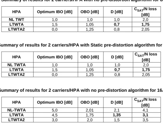
Tables2 and 3 report results for this configuration; in these tables, D represents the demodulator loss due to the non-linearity. Simulations findings indicate that linearized TWTAs work better than the non-linearized one. This is true both for the case when pre-distortion algorithm is used and for the case when the original constellation is transmitted. LTWTA2 provides the smallest demodulation loss (D) at the price of higher OBO. The total loss is slightly higher than for LTWTA, that has a less linear characteristic but lower OBO. Furthermore, using simple static constellation pre-distortion the L-TWTA can bring about 0,3-0,4 dB gain over classical TWTA, whereas without pre-pre-distortion the gain goes up to 0,8 dB. The performance of NL-TWTA, when a pre-distorted constellation is used, is comparable to the one of the linearized TWTA without pre-distorted constellation. Since the AM/AM characteristic of the two amplifiers is very similar in the region of interest when IBO>12 dB, the advantage appears to be related to the flatter AM/PM characteristic of the linearized amplifier.
Table 2: Summary of results for 1 carrier/HPA with no pre-distortion algorithm, 16APSK 3/4
HPA Optimum IBO [dB] OBO [dB] D [dB] CSAT/N loss [dB]
NL-TWTA 4,5 1,5 1,7 3,2
LTWTA 4 1,3 1,1 2,4
Table 3: Summary of results for 1 carrier/HPA with Static pre-distortion algorithm, 16APSK 3/4
HPA Optimum IBO [dB] OBO [dB] D [dB] CSAT/N loss [dB]
NL-TWTA 2 1 1,4 2,4
LTWTA 2 1,0 1,0 2,0
LTWTA2 2 1,35 0,8 2,15
4.3.2.1.2
Sensitivity to roll-off
Decreasing the roll-off factor causes an increase of the loss over non-linear channel due to the fact that the ISI becomes stronger. Simulations carried on with the same channel model and phase noise as for the previous case have shown however that the resulting effect is only marginal. A roll-off factor of 0,2 produces a loss of about 0,1 dB w.r.t. the case of roll-off 0,3 for all the modulation schemes, in case of adoption of static pre-distortion techniques. Similar results are expected when using dynamic pre-distortion.
4.3.2.2
Multiple carrier per transponder configuration
In [38] simulations of multi-carrier systems have been carried out on the same satellite channel model as in
clause 4.3.2.1. 8PSK rate 2/3 and 16APSK rate 3/4 have been tested in this configuration. Results for 2 carrier/HPA are summarized in tables 4 to 7. From the tables is immediately clear that there is no great advantage in using a
pre-distortion technique for none of the modulation schemes when 2 carriers travel along the same amplifier. As expected the conventional TWTA (NL-TWTA) behaves worse than the others. Recalling the characteristics of the two linearized tubes defined in clause 4.3.2.1 (figures 7 and 8), LTWTA2 is expected to behave better than LTWTA, since its AM/AM characteristic is more linear. Such a thesis does not match the results. Indeed, despite a slightly less demodulation loss (D column), the OBO of LTWTA2 is higher and makes the total loss higher. Therefore, once more, this indicates the importance of OBO factor for the total degradation of the whole system.
From the same results it appears that the use of pre-distortion techniques does no mitigate the total loss. It is then clear that when two or more carriers go through the same tube, the intermodulation products due to the non linearities represent the main contribution to the global ISI. Therefore, neither a static pre-distortion technique nor one with memory can attenuate this contribution.
A positive outcome of using pre-distortion techniques is the reduced OBO that results in a slightly higher DC to RF conversion efficiency (see tables 6 and 7).
Table 4: Summary of results for 2 carriers/HPA with no pre-distortion algorithm for 8PSK 2/3
HPA Optimum IBO [dB] OBO [dB] D [dB] CSAT/N loss [dB]
NL TWT 1,0 1,0 1,0 2,0
LTWTA 1,5 1,05 0,7 1,75
LTWTA2 0,0 1,25 0,8 2,05
Table 5: Summary of results for 2 carriers/HPA with Static pre-distortion algorithm for 8PSK 2/3
HPA Optimum IBO [dB] OBO [dB] D [dB] CSAT/N loss [dB]
NL TWTA 1,0 1,0 1,0 2,0
LTWTA 1,5 1,05 0,7 1,75
LTWTA2 0,0 1,25 0,8 2,05
Table 6: Summary of results for 2 carriers/HPA with no pre-distortion algorithm for 16APSK 3/4
HPA Optimum IBO [dB] OBO [dB] D [dB] CSAT/N loss [dB]
![Table 10 associates them to the system configurations and mechanisms specified in [2], either defined as "Normative"](https://thumb-us.123doks.com/thumbv2/123dok_us/10043681.2903746/38.892.81.816.329.829/table-associates-configurations-mechanisms-specified-defined-normative.webp)