Schema Mediation and Query Processing
in Peer Data Management Systems
by Jie Zhao
B.Sc., Fudan University, 2003
A THESIS SUBMITTED IN PARTIAL FULFILMENT OF THE REQUIREMENTS FOR THE DEGREE OF
Master of Science in
The Faculty of Graduate Studies (Computer Science)
The University Of British Columbia October 2006
c
Abstract
P2P Data Management Systems (PDMSs) allow the efficient sharing of data between peers with overlapping sources of information. These sources share data through semantic mappings between peers. In current systems, queries are asked over each peer’s local schema and then translated using the se-mantic mappings between peers. In this thesis we propose that a mediated schema can benefit PDMSs by allowing access to more data and by making that access comprehensible. We present our system - MePSys, which uses the mediated schema as a media for query translation in relational PDMSs. We show how to create a mediated schema in PDMSs automatically using the semantics of the existing mappings provided to translate queries. We further discuss how to update the mediated schema in a stable state, i.e., after the system setup period.
Table of Contents
Abstract . . . ii
Table of Contents . . . iii
List of Tables . . . vi
List of Figures . . . vii
Acknowledgements . . . ix
1 Introduction . . . 1
1.1 Overview . . . 1
1.2 A Motivating Example of PDMS . . . 3
1.3 Challenges and Contributions . . . 5
2 Preliminaries . . . 10
2.1 Definitions w.r.t. Mediated schema creation . . . 10
2.1.1 Datalog . . . 10
2.1.2 Mediated Schema, LAV, GAV and GLAV . . . 10
2.1.3 Query and Mapping . . . 13
2.2 Definitions w.r.t. PDMS . . . 14
2.2.1 Query Reformulation and Result Reformulation . . . . 14
2.2.2 Mapping Composition . . . 15
3 Related Work. . . 16
3.1 Peer Data Management Systems . . . 16
Table of Contents
4 Introducing Concept into Conjunctive Mappings . . . 19
4.1 Motivation . . . 19
4.2 Definitions and Analysis . . . 21
5 Creating a Mediated Schema in PDMS . . . 25
5.1 Pottinger’s Schema Mediation Algorithm for DIS . . . 25
5.2 Problem Definition . . . 27
5.3 MappingTable Creation . . . 34
5.3.1 Intuitions . . . 34
5.3.2 Algorithm . . . 35
5.3.3 Section Summary . . . 36
5.4 Mapping Compatible Check . . . 37
5.5 Peer Schema Mediation . . . 39
5.5.1 System Setup Phase - Schema Mediation . . . 40
5.5.2 Section Summary . . . 49
6 Updating the Mediated Schema . . . 50
6.1 Adding a New Peer to the System . . . 50
6.1.1 Algorithm . . . 53
6.2 Dropping a Peer from the System . . . 54
6.2.1 Section Summary . . . 61
6.3 Evolution of a Peer Local Schema . . . 61
7 A Study of Mapping Composition. . . 63
7.1 Complexity: Where Difficulties Come From . . . 63
7.2 Exploring Possible Patterns in Mapping Composition . . . 66
7.2.1 Different Patterns of Mapping Composition . . . 68
7.2.2 An Analysis of Mapping Composition Patterns . . . . 73
8 System Implementation and Experiment . . . 76
8.1 System Implementation and Setup . . . 76
8.2 Input Schemas and Mappings . . . 77
8.3 Experiment 1: Schema Mediation . . . 77
Table of Contents
8.5 Experiment 3: Updating the Mediated Schema . . . 81
9 Conclusion and Future Work . . . 84
Bibliography . . . 86
A Details for Example 15 . . . 89
List of Tables
7.1 A Summary of Mapping Composition Complexity from [11, 18] 67 7.2 Different Patterns for Mapping Composition . . . 71 8.1 Updating the Mediated Schema for Adding a New Peer . . . 82
List of Figures
1.1 Query Processing in traditional PDMS . . . 4
5.1 The CreateMediatedSchema Algorithm from [22] . . . 26
5.2 The CreateMapping Algorithm from [22] . . . 27
5.3 Query Rewriting Algorithm from [22] . . . 28
5.4 Query Processing in MePSys . . . 29
5.5 MappingTable for Example 6 . . . 34
5.6 MappingTable for Example 12(a) . . . 35
5.7 MappingTable for Example 12(b) . . . 35
5.8 Create MappingTable Algorithm . . . 37
5.9 Merge MappingTable Algorithm . . . 38
5.10 Update MappingTable Algorithm . . . 39
5.11 Mapping Compatible Check Algorithm . . . 40
5.12 Schema Mediation Start-up . . . 41
5.13 System Setup Algorithm . . . 43
5.14 Merge Two Mediated Schema Algorithm . . . 45
5.15 Compute GLAV Mapping Algorithm . . . 46
5.16 Query Reformulation Algorithm . . . 48
6.1 Adding a New Peer to the System . . . 51
6.2 Update mediated information when new peer joins the network 53 6.3 Peer Leaving (Bad Topology) . . . 57
6.4 Update mediated information when a peer leaves the network 58 6.5 Example 17 Input Information (a) . . . 59
6.6 Example 17 Input Information (b) . . . 59
List of Figures
6.8 Example 17 Output (a) . . . 61 6.9 Example 17 Output (b) . . . 61 6.10 Example 17 Output (c) . . . 62 8.1 Time of building a mediated schema V.S. Number of Hops . . 79 8.2 Time of Query Reformulation and Broadcasting V.S. Depth
of Topology . . . 80 8.3 Time of Query Reformulation in the network V.S. Max Local
Acknowledgements
I would like to thank all of people giving me support and help during my study at UBC. Without your support, this thesis cannot be done.
First of all, I would like to thank my supervisor, Rachel Pottinger, for always giving me support, encouragement and excellent guidance throughout my thesis work. I spent a wonderful time working with Rachel for the past one and half years.
I would like to thank George Tsiknis for dedicating time and effort in reviewing my thesis and giving me valuable comments and advise.
I would like to thank all my friends in the department and in the database lab for your continuous help, and especially the following people: Shaofeng Bu, Gang Peng, Xun Sun, Shuan Wang, Wendy Wang, Jian Xu, Chao Yan, Suling Yang and Xiaodong Zhou.
Last, I would like to thank my parents and Alex Liu for their endless love and support.
Jie Zhao October 2006
Chapter 1
Introduction
1.1
Overview
A peer-to-peer (P2P) network is a network in which every participating node in the network provides power, bandwidth and other resources rather than only relying on a small number of servers. It is a decentralized and dis-tributed system. Compared to a client-server architecture where the number of servers are fixed, P2P is more flexible and extensible because when new nodes arrive, the total capacity of the system increases accordingly while in client-server environment, the adding of new clients means the slowing down of the whole system. P2P systems are very useful and famous nowa-days among users who want to share files while users are everywhere across the world. For example, Napster [3] is a successful system for music sharing using P2P infrastructure.
A Peer Data Management System (PDMS) (e.g. [7, 8, 14, 24]) is the result of blending the benefits of peer-to-peer (P2P) networks, such as lack of a centralized authority, with the richer semantics of a database. Peer Data Management System (PDMS) is a Data Management System using P2P architecture. Each peer in the system holds a database. It can be extensively used for data exchanging, query answering, information sharing, etc. In the areas of scientific research, the idea of setting up a PDMS for research in the related area to share data among peers has already been widely discussed and admitted.
A PDMS, as a P2P system itself, keeps the properties of all P2P systems: Every peer may join and leave the network at any time. All peers are autonomously created and managed. However, A PDMS also requires that each peer, upon entering the network, publishes its database schema so that
Chapter 1. Introduction
it can be seen by other peers in the network, and the entering peer must create a mapping between itself and one or more neighbors. We call peers between which there exists a direct mappingacquaintances. These inter-peer mappings allow query translation schemes [8, 24, 26] which allow users to easily, semantically query data from sources that are not their own. PDMSs are a data management architecture where not all nodes in the system need to be there constantly.
PDMSs are often compared with a Data Integration System (DIS) which uses a client-server architecture. A major differences between a DIS and PDMS is the centralized control. In a traditional DIS, there is always one or more central servers to store a global view for all clients’ database schemas. Queries are typically posed over the global schema and then translated to local schemas. All the query processing work such as query translation, query forwarding, receiving answers, and translating answers entirely relies on those servers. Thus, if the servers break down, or become unavailable, the whole system will fail. Considering the workload of the whole system, the centralized control definitely results in a severe bottleneck. On the other side, a PDMS is a dynamic and loosely-coupled environment. There are no central servers in the PDMS. Every peer is both a server and a client. Even though, some nodes might take more responsibilities, e.g., super-peer-structured P2P system, these nodes are still not taking the responsibilities of controlling all nodes, and the resulting architecture is more decentralized. In most current PDMSs, a query is posed over a local peer schema, and answers will be computed in this peer database. The query will also be forwarded and reformulated to other peers in the network, and query results will be sent back. The final result set returning to the user will be answers from the local peer as well as those from other peer databases.
The goal of this thesis is to study the properties of a PDMS, compare and survey existing PDMSs, and look for more opportunities to improve the current PDMS design to let the users have a better understanding of the query processing result and to speed up the query reformulation process among peers.
Chapter 1. Introduction
1.2
A Motivating Example of PDMS
Given the above properties of flexibility and decentralization, a PDMS is very suitable for scientific research data sharing and exchange [21]. There are many scenarios where a PDMS would be useful. In bioinformatics this has already been studied from both the data management approach [17, 21] and also from the bioinformatics approach [25]. Imagine that the Biology labs from different universities are doing research in similar areas. Some might have a partial gene sequence data of a sparrow, and some might have another partial gene sequence data of a sparrow. Researchers from either lab wants more data for further experiment. Even though their results have been published, the data still need some way to be shared by others. Thus a PDMS where each peer comes from a biology lab doing similar gene expression research can handle such a task well. In general, the types of scenarios that we can imagine that would benefit the most from a PDMS are those scenarios where people have overlapping structured data, and they want to access other sources’ additional structured information.
Rather than relying on readers having an understanding of the intrica-cies of biological data, we present a scenario which is familiar to readers of Computer Science area: bibliography management in Example 1.
Example 1 Assume that there are two database servers of bibliography in-formation: UBC and UW, and that they have the following relations storing information about conference papers:
UW.conf-paper(title, venue, year, pages) UBC.conf-paper(title, conference, year, url)
As in this example, it is very likely that each database server only stores part of the record about conference papers, e.g., only UW has page infor-mation and only UBC has url. Additionally, even though they may have overlapped record for the same paper, the content might still be different. For instance,(“Data Management for Peer-to-Peer Computing: A Vision”, “Madison, Wisconsin, USA”, “2002”, 6) is one data entry in UW.conf-paper;
Chapter 1. Introduction
(“Data Management for Peer-to-Peer Computing: A Vision”,“WebDB”, “2002”, “citeseer.ist.psu.edu/bernstein02data.html”) is the data entry for the same paper in UBC.conf-paper. Given the similarity of relations above, along with the difference in available data, it would be beneficial for users of the two databases to be able to share their data on conference papers.
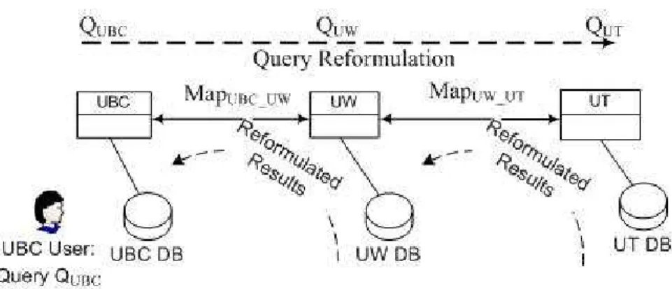
Figure 1.1: Query Processing in traditional PDMS
Figure 1.1 is a picture to explain how queries are propagated and trans-lated back in the P2P systems. In most PDMSs (see figure 1.1) a user at peer UBC will ask a query posed over UBC’s schema. Answers are com-puted at UBC, and the query is also reformulated and forwarded to other peers through mapping paths in the network. For example, assume UBC has a mapping M apU BC U W to UW. Using M apU BC U W, a query QU BC will be asked over UBC and then reformulated toQU W, a query over UW’s schema. QU W will be processed at peer UW. UW will reformulateQU W to query over any additional acquaintances’ schemas in the same way. Thus queries can be forwarded as far along the mapping path as possible, subject to system constraints. Query results will be sent back to the peer UBC after a similar series of reformulations. Thus, the user at UBC will get answers not only from local database but from other peer database as well.
Chapter 1. Introduction
1.3
Challenges and Contributions
The methods in Example 1 have been well studied and allow translation and answering of a large class of queries [26]. However, when the full context is looked at, there are additional opportunities for improving the usefulness and comprehensibility of query translation in PDMSs, which we tackle in this thesis.
First, we get rid of the restrictive query format. In previous methods, only information supported by the local schema can be queried. Further, a user at a peer cannot know what other information is available in the net-work. The user can only see the local schema, despite the fact that actually there is much more information in the PDMS. This is clearly suboptimal; since the information is present, users should be able to fully utilize these resources and not be restricted by the format of local schemas. For example, in Example 1, users at UBC would be unable to access thepageinformation at UW because they can only ask queries over their own schema.
Second, we improve the comprehensibility of the PDMS. Current sys-tems can either fail to take into account some expressiveness available to the system, or result in systems that are difficult to understand, as is shown in Example 2:
Example 2 Consider the following mappings, where (2.1) relates source A to target B, and (2.2) relates source B to target C.⊆ means the left-hand side is a subset of the right-hand side. Attributes in different sources that can be mapped to each other are using the same variable names.
A.grandpa(x,y) ⊆B.father(x,x1), B.father(x1,y) (2.1) B.father(x, x1),B.father(x1,x2), B.father(x2, y)
⊆C.greatgrandpa(x,y) (2.2)
This is isomorphic to a mapping in [20]. (2.1) says that if x is the grandpa ofy, then there is somex1 such thatx is x1’s father, and x1 isy’s
father. Mapping (2.2) says that if x and x1,x1 and x2, x2 and x3 all have
Chapter 1. Introduction
algorithm described in Piazza [20], composing mappings (2.1) and (2.2) to map source A to source C results in:
A.grandpa(x,x2), A.grandpa(x2,y) ⊆C.greatgrandpa(x,y1) (2.3)
(2.3) says that if x is x2’s grandpa and x2 is y’s grandpa, then x is
somebody’s great grandpa. However, (2.3) does not express any constraint on y1: from the given information, it is clear that y1 is the father of y
and x2 is the father of y1; Piazza is not expressive enough to express that
restriction. While the mapping language used by Fagin et al. [10] has enough expressive power to handle the same example, the final results using [10]’s algorithm are difficult to comprehend. The reason for this is that [10] uses second-order logic dependencies to express their mappings. Thus for all those mappings with unbound attributes (attributes that appear in the target but do not appear in the source) in the first-order logic, e.g. x1 in
(2.1), [10]’s mapping language can use ∃ and ∀ to explain the constraints for these attributes. However, when there are too many constraints in the mapping, the readability of the mapping itself will be decreased.
In our system, we make the system more comprehensible by providing a comprehensible mediated schema, and each local schema will be related to the mediated schema so that users of both the local schema and the mediated schema can easily understand the system.
Third, we provide more semantic query processing. In traditional P2P file systems, copies of the same file on different peers can be viewed as grouped into the same file; each may contain different parts of the original file. Consider the scenario of a PDMS. Data of the same topic (which is expressed as “Concept” in this thesis) are dispersed among peers. When data are grouped according to the topic in advance, it will be very easy to help the peers exchange data and make the query processing fast.
Fourth, we reconsider the difficulties and complexity raised by map-ping composition, and see whether such complexity can be avoided in real systems.
Chapter 1. Introduction
Fifth, we make good use of indirect mapping information. We call the information found in the composed mapping that is not included in the direct mappingindirect mapping information. Previous methods tend to reformu-late queries based on single sources of mapping information. However, in real systems, it is very likely that different mapping routes can complement each other for query reformulation. Query answers will be improved a lot if we consider different mapping routes and indirect mapping information.
Taking into consideration of all these opportunities, this thesis only con-siders the mappings that can group data into topics, and proposes automat-ically creating and maintaining a mediated schema to take advantage of the above insights to improve functionality for PDMSs. For other mappings, the same method proposed in Piazza is adopted in our system. This has many advantages. First and foremost, users are able to access more information residing in the network than in previous systems. Second, we create the mediated schema using the pre-existing mappings, thus users have the flex-ibility to use either the mediated schema or use their local schema as they use previously existing methods, (e.g., those in Piazza [26]). Third, using our method, the translation of queries over the mediated schema into the sources is simple and effective. Finally, as will be shown in the experiment, our query processing method using a mediated schema is much faster than other methods, which won’t slow down the whole system but will ensure a comprehensible PDMS.
However, creating a mediated schema in a PDMS setting requires an-swering difficult questions such as:
- How can the mediated schema be created without a centralized au-thority?
- How can an automatically created mediated schema be comprehensible to users?
- Since the system is dynamic, the maintenance of a mediated schema must be automatic and adaptive; how can human intervention be min-imized?
Chapter 1. Introduction
- Where is the mediated schema stored, and how is it updated?
In this thesis, we begin to answer the above problems. We make the following specific contributions:
- We describe our PDMS system, MePSys (Mediation supported Peer Data Management System), in which a mediated schema can be cre-ated dynamically and any information in the network can be queried without requiring any additional global services in the network. - We outline our Peer Schema Mediation algorithm (PSM algorithm)
which is used to efficiently create the mediated schema representing all schemas in the network, and introduce MappingTables as a mechanism for relating the mediated schema to the sources.
- We study the semantics of mappings and introduce the idea of auto-matically detecting specificConceptsin mappings. A mediated schema based onConcepts is much easier for users to understand.
- We study how mapping composition impacts query reformulation and how to discover common Concepts in composed mappings to ensure comprehensible query results.
- We study how to solve the problem of updating the mediated schema in our infrastructure.
- We design experiments to test the efficiency and scalability of MePSys. This thesis is organized as follows. In Chapter 2, we introduce back-ground knowledge related to this thesis. We discuss related works in Chap-ter 3. In ChapChap-ter 4, we define and analyze the semantic information that can be presented in a conjunctive mappings. We present our approach to creating a mediated schema in a PDMS and creating the mappings from the mediated schema to local sources in Chapter 5, including algorithms and examples. We further describe how to update the mediated schema in Chapter 6. We show our system implementation setup and the experimental
Chapter 1. Introduction
results in Chapter 8. We then study the mapping composition problem that can impact the correctness and capability of query translation in the system in Chapter 7. Chapter 9 concludes and discusses future work.
Chapter 2
Preliminaries
2.1
Definitions w.r.t. Mediated schema creation
Definitions in this section are related to the mediated schema creation.2.1.1 Datalog
Datalog, a subset of Prolog, is a query and rule based language. It is a logic-based query language for the relational model.
Take the following clause as an example:
Example 3 grandpa(x, z) :- father(x, y), father(y, z)
Each clause in Datalog is composed of two parts: head and body, which are separated by “:-”. In Example 3,grandpa(x, z) is the head, andfather(x, y), father(y, z)are collectively the body. The body can be viewed as conditions known, and the head can be regarded as the query. The above clause can be interpreted as: ifxisy’s father andyisz’s father, thenxisz’s grandpa. Each relation (e.g. father) is called a predicate. Each term in the predicate (e.g.,
x and y) can either be a variable or a constant. For safety, only variables that appear in the body can appear in the head.
2.1.2 Mediated Schema, LAV, GAV and GLAV
A data integration system is a system that combines data residing at dif-ferent sources and provides the user with a unified view of these data. A mediated schema, also called a global schema, is usually provided in a Data Integration System. Every local source has its own database schema, which is called the local schema. A mediated schema is a unified view of all these
Chapter 2. Preliminaries
local databases so that through the mediated schema, users can query over only the mediated schema and get results from all local sources.
There are two basic approaches in a data integration system to specify mappings between the mediated schema and the local schemas: Local-As-View (LAV) and Global-As-Local-As-View (GAV). In LAV, the content of each lo-cal source s should be characterized in terms of a view qG over the global schema; in GAV, the content of each elementg of the global schema should be characterized in terms of a viewqS over the local sources [19].
Example 4 To explain these definitions, consider Example 1 again. Two local databases UW and UBC are presented with the database relations as below.
UW database:
UW.conf-paper(title, venue, year, pages)
UBC database:
UBC.conf-paper(title, conference, year, url)
A mediated schema M is manually created as:
M.conf-paper(title, conference, venue, year)
Using LAV, UW.conf-paper and UBC.conf-paper will be explained as a view of the mediated schema:
UW.conf-paper(title, venue, year, pages)
:-M.conf-paper(title, conference, venue, year) UBC.confpaper(title, conference, year, url) :
-M.conf-paper(title, conference, venue, year)
Using GAV, M.conf-paper can be expressed as the view of all local schemas.
M.conf-paper(title, conference, venue, year) :-UW.conf-paper(title, venue, year, pages) M.conf-paper(title, conference, venue, year)
Chapter 2. Preliminaries
GLAV, firstly introduced in [12], is a more generalized approach to specify mappings between sources. GLAV mapping language adopts both GAV and LAV in its presentation, which allows a flexible schema definition and combines the expressive power of both GAV and LAV. Example 5 shows an example of GLAV mapping relating different schemas.
Example 5 Assume UW and UBC have the following schemas. UW database:
UW.research-area(area, groupleader, department) UW.grad-student(stu-name, area, advisor)
UBC database:
UBC.faculty(name, office, department)
A mediated schema M is manually created as:
M.people(name, department)
Using GLAV, relationship between the source schema and the mediated schema can be freely expressed.
GLAV mapping between UBC and M
UBC.faculty(name, office, department)
→ M.people(name, department)
GLAV mapping between UW and M
UW.grad-student(stu-name, area, advisor),
UW.research-area(area, gl, department)
→ M.people(name, department)
The above GLAV mappings can also be rewritten in conjunctive map-pings.
Chapter 2. Preliminaries
GLAV mapping between UBC and M LAV:
Q1(name, department):-M.people(name, department)
GAV:
Q1(name, department):-UBC.faculty(name, office, department)
GLAV mapping between UW and M LAV:
Q2(name, department):-M.people(name, department)
GAV:
Q2(name, department):-UW.grad-student(name, area, advisor), UW.research-area(area, gl, department)
2.1.3 Query and Mapping
A mapping is the medium for exchanging data and reformulating queries among different schemas; in particular, the mapping defines the overlapping parts of acquaintances’ schemas. As such, it is the most basic and impor-tant part of the system. We use conjunctive mappings [27] as our mapping language. These are the same mappings as in [22] and [20]. We choose conjunctive mappings as our input mapping because they can easily express commonality among different schemas and allow the use of existing algo-rithms if the mediated schema is not used, e.g., through the methods in [26] which just compose the mappings between peers. Aconjunctive mapping is a set of conjunctive queries relating a pair of local schemas: i.e., a set of simple Datalog queries. We briefly review the syntax of conjunctive queries in Example 6. In a conjunctive mapping, if a set of conjunctive queries has the same IDB name (i.e., name of the answer relation), that set expresses the overlapping information in the sources. Note that we still use mapping to refer to the general sense of correspondences between schemas. Each con-junctive query in the concon-junctive mapping is also called acomponent, which relates to one schema for that mapping. In a conjunctive query, variables
Chapter 2. Preliminaries
that appear in both the head and the body are calleddistinguished variables; variables that appear only in the body are calledexistential variables. Example 6 Consider the following conjunctive mapping on the schemas in Example 4:
conf-paper(title,venue,yr):-UW.conf-paper(title,venue,yr,pages) conf-paper(title,venue,yr):-UBC.conf-paper(title,venue,yr,url)
This mapping shows how UBC and UW can share information about conference papers through the reuse of the IDB name conf-paper. Each line is a conjunctive query. conf-paper(title,venue,yr) is the head of both queries, and title, venue, and yr are head variables, indicating that these are the common attributes in the two schemas. As in general Datalog, the semantics imply that conf-paper information can be found by taking the union of title, venue, and yrattributes found from the bodies of the two queries. The bodies express the conditions required to form an answer tuple, and reuse of a variable indicates that those values must be the same. Each relation in the body of a query is referred to as a subgoal. Together, the conjunctive queries show that information about conf-papers can be found through either UW.conf-paper or UBC.conf-paper, and all information that can be obtained from the topic conf-paper are title, venue, yr, page and url
information. Note that the IDB name of a subgoal is the subgoal name.
2.2
Definitions w.r.t. PDMS
2.2.1 Query Reformulation and Result Reformulation
Query reformulation is the process of translating a query over database schema A to that over database schema B so that queries over A can be understood by schema B. The reformulation process follows the mappings between these two schemas. Accordingly, result reformulation is the process of translating the results using database schema A to those over database schema B so that results obtained at schema A can be understood by schema B.
Chapter 2. Preliminaries
2.2.2 Mapping Composition
Mapping composition is a hard problem which draws much attention re-cently. Intuitively, when given semantic mappings M12 from schema A to
B, andM23from B to C, we hope we could compute a direct mappingM13
from A to C which is equivalent to the composition of mappings M12 and M23.
Halevy et al. provided a formal definition of mapping composition: “The mappingMA→C is a composition of the mappingsMA→B andMB→C w.r.t.
a query languageQif for all databasesDAforRA, and for all queriesq over
RC such thatq is in the languageQ, the certain answers forq w.r.t. MA→C
are the same as the certain answers w.r.t. MA→B andMB→C.” [20]
Fagin et al. defined the mapping composition in more logical sense: “Let
M12 =(S1,S2, Σ12) and M23 =(S2,S3, Σ23) be two schema mappings such
that the schemas S1, S2, S3 have no relation symbol in common pairwise.
A schema mapping M = (S1, S3, Σ13) is a composition of M12 and M23 if
Inst(M) = Inst(M12)◦Inst(M23), which means that Inst(M) ={<I1;I3>|
there existsI2 such that<I1;I2>∈Inst(M12) and<I2;I3>∈Inst(M23)}.”
“A schema mapping is a tripleM = (S,T, Σst), whereS andT are schemas with no relation symbols in common and Σst is a set of formulas of some logical formalism over <S,T >.” [11]
Mapping composition is a problem that costs high complexity when con-sidering all classes of mappings. In Chapter 5, we explore and analyze map-ping composition problem in more depth.
Chapter 3
Related Work
3.1
Peer Data Management Systems
For a long time, P2P computing and Database research groups were very independent. The idea of incorporating the database research into P2P was proposed and discussed early this century by Gribble et al. [13] in 2001, Bernstein et al. [7] in 2002. The paper by Bernstein et al. introduces the Local Relational Model (LRM) as a data model specifically designed for P2P applications. Most research projects in PDMS build their architecture by extending LRM, (i.e. Piazza [14], HePToX [8], Hyperion [24]). LRM assumes that the set of all data in a P2P network consists of local (relational) databases, each with a set of acquaintances, which define the P2P network topology. For each acquaintance link, translation rules between data items and semantic dependencies between the two databases are predefined [7]. Our system also uses such a model.
Piazza [14, 15, 20] is a well-known prototype for Peer Data Management System. Piazza uses GAV/LAV style mappings to describe the semantic relationships between two peers. Our mapping is based on the Piazza map-ping, but changed into conjunctive mapping for better understanding. Pi-azza also provides a query reformulation algorithm [26] based on XQuery to translate the queries among peers using different schemas. Unlike our solution, they do not support a mediated schema in their prototype, which is flexible for query translation. Our solution uses the similar initial setup but ensures a better understanding of the system, access to more informa-tion and a faster query reformulainforma-tion. However, since our system uses the same mappings as Piazza, users of our system could choose to use either our query answering system or translate their queries using Piazza’s system.
Chapter 3. Related Work
HePToX [8, 9] is a P2P XML database system. A novel query translation algorithm has been developed for a simple but a significant fragment of XQuery. Both Piazza and HePToX assume that all queries are asked over a local schema; they focus on finding a query reformulation algorithm to translate a query over one peer schema to a query over its acquaintance.
The works of Fagin et al. [10, 11] mainly consider how to process data exchange and mapping composition without information loss using mappings under second-order logic dependencies. They provide a nice solution for mapping composition which they uses for their query translation.
Hyperion [5, 24] is also a Peer Data Management System which uses both data-level and schema-level mappings to specify the correspondences between acquainted peer databases and process query reformulation based on these mappings. Mapping tables are used to specify correspondences between data values of acquainted databases. This is the key difference between Hyperion and all other systems.
In PeerDB [21], local peer schemas are not published. Instead, local users input keywords from relation name, attributes, and records for each peer database, and such information is used to match relations.
As in previous PDMSs: a new peer entering the network chooses one or more acquaintances and provides mappings to one or more acquaintances, either created by hand, or through some schema matching tool (see [23] for a survey). Our system has the following minimal features:
Peer: each peer stores both its local schema and one or more versions of mediated schema that local peer has an application built on. Only the mappings from mediated schema to its local schema will be stored at this local peer, which is used for query answering. Each peer will also store MappingTables, which help create the mediated schema and determine how to relate the mediated schema to the peer’s schema.
Query answering: users can either query the local schema (as in previous systems) or use the automatically-created mediated schema, which provides additional information. In either case, user queries are automatically refor-mulated and forwarded to the peers’ acquaintances.
Chapter 3. Related Work
3.2
Mediated Schema Creation
Another aspect of our research is mediated schema creation (MSC). MSC has been studied in data integration area. Batini, Lenzerini, and Navathe [6] conducted a survey for database schema integration early in 1986. In [6], methodologies for schema integration and a comparison of all available methodologies are provided. Later, Lenzerini [19] and Ullman [28] both discussed data integration techniques in very theoretical perspective. How-ever, most early work ignores creating the mappings between the mediated schema and the sources.
Pottinger provided a method for creating a mediated schema and map-pings from the mediated schema to sources [22]. However, [22] does not consider the complications of the PDMS situation, including the fact that mappings can exist between any pairs of schemas, rather than those dictated by a centralized authority. Our schema mediation method is based on [22]. However, we have the following improvements: our MSC method can handle any numbers of local schemas, while the one in [22] can only handle a limited number of local sources. In our approach, any ordering of mediating local schemas will get an equivalent result while in [22], different ordering of local schemas might get totally different mediated schema and mappings to local sources. This is let’s assume that we use a different approach from theirs. For example, when we have three peers A, B, C mappingM apA B between A and B, and mappingM apB C between B and C. Pottinger’s approach to create a mediated schemaMAB is firstly based on schemaA,Band mapping
M apA B. Then mappings M apAB B and M apB C are composed to get the mapping M apAB C. Using schemas MAB, C and mapping M apAB C, the mediated schema of ABC can be created. Using our approach, we create the intermediate mediated schemas MAB and MBC first. Then we create a mapping M apAB BC based on the overlapped subgoals in the mappings
MAB andMBC, and create the final mediated schema and mappings to local sources.
Chapter 4
Introducing Concept into
Conjunctive Mappings
Before we delve into the PSM algorithm, we start by studying two related problems: what are the things that can be represented by the same relation in the mediated schema, and what is the complexity of mapping composition in such a system. We explore the first problem in this chapter, and explore the second one in chapter 7.
The definitions of Conjunctive Mapping and Conjunctive Query have been introduced and explained in section 2.1.3. In this chapter, we explore how to support semantics in the conjunctive mapping by applying some restrictions on the conjunctive mappings. We first present the motivation of introducing the idea of “Concept” into conjunctive mappings in section 4.1. We then use some examples to analyze what kind of restrictions should be applied to the mappings in order to let the mappings have aConcept. We give the formal definition of aConcept in section 4.2.
4.1
Motivation
One of our contributions is to introduce the notion of Concept into con-junctive mappings. Previous work either ignores the semantics that the mappings might contain [11, 20] or simply assumed that if the IDB name of the queries were the same, then they described the same Concept [22]. The later view, though using the semantic information that is embedded in the mappings, is overly simplistic. However, reusing the same IDB name inside a conjunctive mapping likely indicates the cases that (1) the seman-tics of the mapping may make it impossible to construct an understandable mediated schema if this is the only information taken into account and (2)
Chapter 4. Introducing Concept into Conjunctive Mappings
consistency of IDB names cannot be assumed between mappings - there is no guarantee that the creator of M apA B will use the same IDB name in the same way as the creator ofM apC D to represent the same Concept. In this thesis we begin to understand the semantic issues entailed byConcept. However, as an introductory step, throughout this thesis we assume that when more than one conjunctive mappings express the sameConcept, their IDB names are the same.
Intuitively, a Concept describes the common object among different schemas. This is different from a mapping which expresses the overlapped attributes across schemas. When a mapping is said to have a Concept, the mapping should have a clear object, which might have some aspects to describe it in detail. In Example 6, clearly the mapping describes the object “conf-paper”, which uses five aspects, title, venue, yr, pages and url, to describe this object. However, even though there are common relation names (e.g.,father) and attributes (e.g.,x,x1) occurred in Example 2, these two mappings together do not express a common object or an idea because mapping (2.1) explains theConcept grandpaand mapping (2.2) explains the
Concept greatgrandpa.
Deciding whether or not one mapping can express a Concept evolves much AI research topics such as natural language processing, ontology, etc, and thus is not our focus in this thesis. However, deciding whether two mappings with the same IDB name together can express the sameConcept is very useful, especially when we want to mediate local schemas and propagate queries along the mapping path. There are two reasons. First, users tend to provide incomplete or wrong mapping information when two mappings between two pairs of peer schemas are considered. Second, we want to know whether the pre-defined mappings are truly relating identical parts from different schemas. In this thesis, we only discuss thisConcept problem based on two or more mappings.
Throughout this thesis, the input mappings for MePSys are required to be conjunctive mappings with the same concept (Definition 3) without self-joins in each component. The PSM algorithm is sound and complete for such input mappings.
Chapter 4. Introducing Concept into Conjunctive Mappings
4.2
Definitions and Analysis
In Chapter 2, we introduced conjunctive mappings, including Example 6, which defines oneConcept: conf-paper. However, in many cases determining a Concept from the mapping is not straightforward. Consider Example 7 (originally from [11] but rewritten in the form of a conjunctive mapping). Example 7 Assume the following conjunctive mappings:
Conjunctive Mapping 1: between A and B
Manager(x, y) :- A.Mgr(x, y) (7.1a)
Manager(x, y) :- B.Mgr1(x, y) (7.1b)
Conjunctive Mapping 2: between B and C
Manager(x) :- B.Mgr1(x, x) (7.2a)
Manager(x) :- C.SelfMgr(x) (7.2b)
Both conjunctive mappings use the IDB nameManager. However, while the first conjunctive mapping defines the Manager relationship, the second does not. Though the relationMgr1appears in both conjunctive mappings, in the second mapping, it has more restrictions on its attributes: x must manage itself. Thus,Mgr1(x, x)can no longer represents the idea of Manager but Self-Management instead. Therefore, Example 7 has two Concepts: Manager and Self-Management rather than only one. We call the attributes inB.Mgr1(x, x)in (7.2a) aself-restrictiveattribute, which is defined to be an attribute that is in a subgoal that appears in two conjunctive mappings with the same IDB name but has more restrictions than the same attribute in the other mapping. Correspondingly, component (7.2a) is a self-restrictive
component (Definition 6).
Example 7 shows that it is hard to judge whether two mappings describe the same idea. This thesis provides the first pass at understanding aConcept
which is some common topic or idea that can help make the mediated schema more comprehensible. But what is aConcept in the conjunctive mappings?
Chapter 4. Introducing Concept into Conjunctive Mappings
We begin with the following definition of aConcept in conjunctive mappings, which allows a careful analysis of the cases that are clear-cut. There are additional issues to consider, but in this thesis we focus on these cases that are clear and essential for deciding aConcept.
A Concept is defined by a set of aspects. As in relations in relational databases, theaspects of aConcept are referred to asattributes. For exam-ple, the concept of flight includes the attributes flightNo, date, time, depar-ture, destination, crew, etc, which are the aspects that are used to describe theConcept flight. In a conjunctive mapping, the name of each aspect is the corresponding variable name in the mapping, which represents one aspect of theConcept that the mapping describes.
Definition 1 (Concept in Conjunctive Mappings): AConcept in conjunc-tive mappings is defined as an idea, notion or entity that is common in all schemas that the conjunctive mappings are relating. Formally, aConcept C
is expressed by a set ofaspects S.
For ease of discussion, we provide the following terms and definitions. Definition 2 (Component): Each conjunctive query Q in the conjunctive
mapping is a component [22].
Definition 3 (Same Concept): We say that two conjunctive mappings
CM1 and CM2 define the same concept if the overlapped subgoals in CM1
andCM2 are equivalent subgoal sets, which can be checked as follows:
1. Assume ∀ component c ∈ CM1 ∪ CM2, ∄ c′ s.t. (1) c ≡ c′ (i.e., c ⊆ c′
& c′
⊆c) and (2) |subgoals(c)|>|subgoal(c′
)|; Assume the overlapped schema ofCM1 and CM2 is X;
LetC1 be a component fromCM1 over X;
LetC2 be a component fromCM2 over X.
2. Letname(sg) be the relation name of the subgoalsg;
Chapter 4. Introducing Concept into Conjunctive Mappings
Let overlap names = {name(sg) | name(sg) ∈ sg names(C1) and name(sg) ∈ sg names(C2)};
LetC1overlap={sg|name(sg)∈overlap namesandsg∈body(C1)}; C2overlap = {sg|name(sg) ∈overlap names and sg∈ body(C2)}.
3. We now create new queriesQ1 and Q2 that describe the overlapping
parts of C1 and C2 respectively. The goal is to see if the overlapping
parts are equivalent:
LetIDB(Q1) beIDB(CM1), and let IDB(Q2) beIDB(CM2);
Letsubgoals(Q1) =C1overlap, and subgoals(Q2) =C2overlap;
Let all variables inQ1andQ2be distinguished. That is letvars(head(Q1))
=vars(subgoals(Q1)) and letvars(head(Q2)) =vars(subgoals(Q2)).
Then the following conditions should hold:
1. IDB(CM1) = IDB(CM2) (which, by the above requirement, is also
equal toIDB(Q1) and IDB(Q2));
2. overlap names6=∅;
3. Q1 contains Q2, and Q2 contains Q1 (i.e., they are equivalent).
Additionally, condition (1) is actually the assumption we have made at the beginning. This condition can be removed for further study in the future. Condition (2) says that if schemaXexists in two conjunctive mappings of the sameConcept, at least one relationr should appear in both conjunctive mappings. This ensures that theConcept is compatible in the representation of schemaX.
Condition (3) ensures that if one subgoal name appears in different con-junctive mappings for the same concept, these two subgoals should be ex-actly the same after a substitution of variable names.
Chapter 4. Introducing Concept into Conjunctive Mappings
Example 8 There are other cases when two conjunctive mappings follow the definition of same concept but still are not representing the same Con-cept. Consider the following conjunctive mappings.
Conjunctive Mapping 1: between A and B
student(sid, name) :- A.stu(sid, name) (8.1a)
student(sid, name) :- B.stu(sid, name, program) (8.1b) Conjunctive Mapping 2: between A and C
student(sid, name, advisor) :- A.stu(sid, name),
A.advisor(sid, advisor) (8.2a)
student(sid, name, advisor) :- C.student(sid, name, advisor),
C.student(sid1, advisor, name) (8.2b) Conjunctive mapping 1 and conjunctive mapping 2 together do not vio-late property 1 and 2, but if only consider conjunctive mapping 2, it is easy to find out thatC.student(sid, name, advisor), C.student(sid1, advisor, name)
is not talking about theConcept “student”. This component is actually ex-pressing theConcept of a student that has an advisor and the student is also his advisor’s advisor. However, in this thesis, we only deal with whether two conjunctive mappings can describe the same Concept, rather than deciding whether the given conjunctive mapping itself is correct.
Chapter 5
Creating a Mediated Schema
in PDMS
In our scenario, a mediated schema of all peer schemas and the mappings from the mediated schema to local sources are necessary for query propa-gation and translation. We presented the preliminary knowledge of schema mediation in Section 2.1 and Section 2.2. We also discussedConcept which can be represented as the semantic information in mappings in Chapter 4. In this chapter, we present the definition of schema mediation in P2P settings, and present our approach of creating a mediated schema for a PDMS.
5.1
Pottinger’s Schema Mediation Algorithm for
DIS
Pottinger [22] provides a novel approach for the data integration system to automatically create a mediated schema M based on two local schemas
E and F, and a mapping M apE F between them. Using her algorithm, not only a mediated schema M but the mappings from M to both local sourcesE andF,M apM E andM apM F, will also be generated [22]. In this section we describe Pottinger’s algorithms of creating a mediated schema and mappings to local sources in a data integration system. The algorithm of translation queries is also discussed in this section.
Figure 5.1 shows Pottinger’s mediated schema creation algorithm. There are mainly two categories of relations that will be generated in the mediated schema M: One is directly from local relations. They are not sharing a
Concept with other schemas so that those relations do not appear in any of the mappings. The other is created from mappings. If there is a mapping betweenEandF which expresses something thatE andF bear in common,
Chapter 5. Creating a Mediated Schema in PDMS
ProcedureCreateMediatedSchema(E, F, M apE F)
/∗ E,F are schemas, and M apE F is a conjunctive mapping between them. ∗/ C=∅
ξ=∅
Let R = {r∈E∪F |r /∈a projection-only component} For each relation r∈R
Let m be a new relation name(m) = name(r)
attributes(m) = attributes(r) Addξ(r, m) toξ
Add m to M
For each IDB name q∈IDB(M apE F) Let m be a new relation
Letvarsq be the duplicate-free union of variables of queries that define q inM apE F
name(m) = name(q) attributes(m) =varsq Addξ(q, m) toξ
Add m to M Return M andξ
Figure 5.1: The CreateMediatedSchema Algorithm from [22]
there will be a relation in the mediated schema representing this common idea across the schemas.
A simple subset of GLAV mappings [12] is used to express the mapping from M to E∪F. The heads of queries in M apM E∪F can be treated as
an intermediate schema, IS, which is used to indicate how each mediated schema relation relates to each particular source. Each component (defined in Section 2.1.3)cfrom M apE F creates two views in M apM E∪F. The first
view,lvc, is called a local view forc. It is a conjunctive query fromM toIS.
LVM consists of all such local view definitions forM. The second view,gvc, is called a global view forc. gvc is a query fromE toIS, and is included in
GVM, the global view definitions for M. Figure 5.2 shows the algorithm of creating the mappingM apE∪F.
GivenM andM apM E∪F, any query that is overM can be reformulated
to local sources simply followingLVM and GVM. The query reformulation algorithm is shown in Figure 5.3.
Chapter 5. Creating a Mediated Schema in PDMS
ProcedureCreateMapping(E, F, M apE F, M)
/∗ E andF are schemas,M apE F is a conjunctive mapping between them, and M andξare the outputs from CreateMediatedSchema(E, F, M apE F)∗/
LVM =∅
GVM =∅
For each relation m∈M If e∈E∪F andξ(e, m)
Let q be a fresh IDB name
Letlvm= q(attributes(m)) :- m(attributes(m)) Letgvm= q(attributes(m)) :- e(attributes(e)) AddlvmtoLVM
AddgvmtoGVM
For each component c ∈M apE F Let cname = IDB(c)
Let m be the relation in M s.t. ξ(cname, m) Let q be a fresh IDB name
lvc = q(vars(c)) :- m(attributes(m))
gvc = q(vars(c)) :- body(c) AddlvmtoLVM
AddgvmtoGVM ReturnLVM andGVM
Figure 5.2: The CreateMapping Algorithm from [22]
Formal definitions of a mediated schema in Data Integration System and mapping from mediated schema to local sources, as well as the mediated schema criteria are provided in [22].
5.2
Problem Definition
Just as we have discussed in Chapter 1, a mediated schema which can be used to improve the comprehensibility of query translation will be very desirable in a PDMS. To make this idea more clear, look at Example 9.
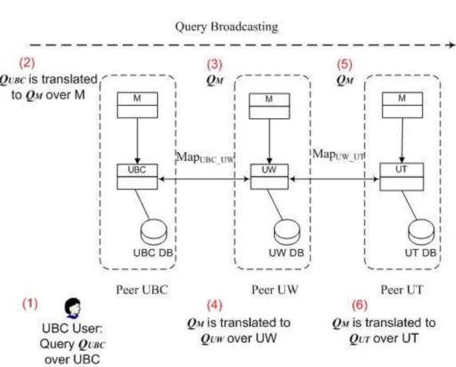
Example 9 Assume that U W, U BC and U T are the three peers with databases storing the following information about conference papers shown in Figure 5.4:
UW.conf-paper(title, author, conference, venue, pages) UBC.conf-paper(title, conference, year)
Chapter 5. Creating a Mediated Schema in PDMS
ProcedureRewriteQuery(M, M apM E∪F, Q)
Q’ = maximally-contained rewriting for Q usingLVM /∗Q’ is over intermediate schema IS ∗/
Q” = expansion of Q’ usingGVM /∗Q” is overE∪F ∗/
Return Q”
Figure 5.3: Query Rewriting Algorithm from [22]
UT.conf-paper(title, author, abstract, area)
The mappings betweenU BCandU W,U W andU T are given as follows: Mapping M apU BC U W: conf-paper(title,conference):-UBC.conf-paper(title,conference,year) conf-paper(title,conference):-UW.conf-paper(title,author,conference,venue,pages) Mapping M apU W U T: conf-paper(title,author):-UW.conf-paper(title,author,conference,venue,pages) conf-paper(title,author):-UT.conf-paper(title,author,abstract,area)
Assume that a mediated schema M is created for all three peers using the above information:
M.conf-paper(title,conference,year,author,venue,pages,abstract,area)
We further assume that the Mappings fromM to each local peer can be obtained using GLAV mappings:
Mapping M apM U BC: LAV:
conf-paper(title,conference,year):-M.conf-paper(title,conference,year,author,venue,pages,abstract,area)
Chapter 5. Creating a Mediated Schema in PDMS
Figure 5.4: Query Processing in MePSys
conf-paper(title,conference,year):-UBC.conf-paper(title,conference,year) Mapping M apM U W: LAV: conf-paper(title,author,conference,venue,pages):-M.conf-paper(title,conference,year,author,venue,pages,abstract,area) GAV: conf-paper(title,author,conference,venue,pages):-UW.conf-paper(title,author,conference,venue,pages) Mapping M apM U T: LAV: conf-paper(title,author,abstract,area):-M.conf-paper(title,conference,year,author,venue,pages,abstract,area)
Chapter 5. Creating a Mediated Schema in PDMS
GAV:
conf-paper(title,author,abstract,area):-UT.conf-paper(title,author,abstract,area)
Now, using these GLAV mappings, queries can be easily translated from over M to any local schema or from any local schema toM.
A user at U BC can ask a query inU BC’s own schema:
q(title):-UBC.conf-paper(title,conference,year)
This query is first translated to that over M usingM apM U BC:
q(title):-M.conf-paper(title,conference,year,author,venue,pages,abstract, area)
Then peerU BC broadcasts this query to all of this acquaintances, and ac-quaintances to acac-quaintances. For example,U W receives this query. Using the MappingM apM U W, this query can be translated to that overU W:
q(title):-UW.conf-paper(title,author,conference,venue,pages)
In the same way, answers can be reformulated and passed back toU BC. Thus,U BC can get not only answers from its own peer database but also from other peer database.
Users at U BC can also pose their query directly over the mediated schema, by using which users are able to query more information in the
network.
Since Pottinger has already provided the related algorithm in [22] (de-scribed in Section 5.1), are these algorithms already enough to create a mediated schema in a PDMS setting? Unfortunately, the answer is no. In a PDMS, any peer can join and leaves the network at any time, so the schema mediation algorithm needs to be commutative and associative and satisfy all the requirement of a P2P system. Though [22] considers to mediate more than two schemas, when the order of local schemas changes, the final medi-ated schema might also change. Furthermore, [22] requires that to include a new local schema E into the previously created mediated schema M, a
Chapter 5. Creating a Mediated Schema in PDMS
mapping fromM toE should be specified. This could be achieved in a data integration system. However, in a P2P system, nobody can be expected to take the responsibility for this task. Also, in a PDMS, it is very likely that two different versions of mediated schema (containing information of differ-ent sets of peer schemas) might meet at some point, a merging operation to merge the two mediated schemas would be inevitable. Such an instance is never expected in a data integration system, nor in [22]. Thus, these new tasks will be tackled in MePSys.
The algorithms of how to create a mediated schema and mappings to local sources in a PDMS setting as shown in Example 9 will be described in the following sections of this chapter.
To create a mediated schema, we extend the algorithms in Section 5.1. This includes (1) usingConcepts to create a more comprehensible mediated schema, (2) ensuring that the algorithm is commutative and associative (since any peer can enter or leave the network at any time). Here we provide the formal definitions of schema mediation in P2P environment. We begin by informally defining Concept Mediation, and then formally define it in Definition 4. We use the definition of Concept Mediation to formalize our definition of Mediated Schema In P2P in Definition 5.
Informally, concept mediation can be explained as the following: Assume that a set of peer schemasS ={P1,P2, ... , Pk} and a set of mappingsM
between some pairs of the schemas are given. Each mapping may contain several conjunctive mappings. Each conjunctive mapping only specifies one aspect of the commonality between the pairs of peers. We assume that all conjunctive mappings with the same IDB name in the set M are talking about the same thing, i.e., more formally they refer to the same concept (Definition 3). We put all the information provided by these conjunctive mappings (defined in Section 2.1.3) together and form a global relation for this concept.
Definition 4 (Concept Mediation): given a set of peer schemas S = {p1, p2, ... ,pk}and a set of mappingsM between some pairs of the schemas, a
Chapter 5. Creating a Mediated Schema in PDMS
and mapping to sources) in the mediated schema that corresponds to those conjunctive mappings in the setM with the same IDB name. Informally, the mediated schema in P2P can be defined as the union of all concepts of its peers. Note that if every concept is calculated by using Concept Mediation, then the Mediated Schema is the union of all mediated concepts. A Mediated Schema should also follow the Information Capacity criteria: all queries that can be asked over the source schemas can be asked over the mediated schema and the same results are returned [22].
Definition 5 (Mediated Schema in P2P): given a set of peer schemas S
= {P1, P2, ... , Pk} and a set of mappings M between some pairs of the
schemas, a Mediated Schema is the union of all resulting relations from Concept Mediation (commonalities between schemas) and those relations existing inS but not existing in any of the subgoals of the mappings in set
M (specialities for local peer schema).
Further, a mappingM apM E from the mediated schemaM to each local source E, i.e. the GLAV mapping between M and U BC in Example 5, is necessary so that a query over M can be reformulated to that over E. In our algorithm, the mappingM apM E is in the form of GLAV, and each peer
E maintains their own GLAV mappingM apM E.
To make the mediation process easier, we introduced a construct Map-pingTable. A MappingTable contains all local information about a specific
Concept. With the use of MappingTable, the presence of indirect mappings that identify additional information about relationships betweens schemas can be fully used. Consider Example 10.
Example 10 : Consider the indirect mapping information in the following mappings:
Conjunctive Mapping A B:
author(name) :- A.auth(name, affiliation, contactInfo) author(name) :- B.author paper(name, paper)
Chapter 5. Creating a Mediated Schema in PDMS
author(name) :- B.author paper(name, paper) author(name) :- C.author(name, affiliation, title)
Conjunctive Mapping A C:
author(affiliation) :- A.auth(name, affiliation, contactInfo) author(affiliation) :- C.author(auth-name, affiliation, title)
For mapping A B and mapping B C, it is clear that the first attributes inA.auth,B.author andC.author are the same since they are mapped to the same variable: name. In mapping A C, the first attributes of A.auth and
C.authorare not mapped to the same variable, so by A C only, it is impossi-ble to tell that they represent the same information. However, by composing A B and B C, it is clear that in the first attributes of A.authand C.author
represent the same information. We call the information found in the com-posed mapping that is not included in the direct mappingindirect mapping information. One advantage of our work is that such indirect information can complement information in the original mappings. Previous work tends to focus on translating queries on a single source of information, either from the original mapping or from the composed mapping. Since users are likely to provide incorrect or incomplete mapping information, our system helps users check whether their mappings are correct, and the system will auto-matically combine all mapping information together, regardless of where the information comes from.
In Section 5.3, we introduce the use of a MappingTable to merge all mapping information, not just the direct information. In Section 5.4 we introduce the idea and the algorithm of a mapping compatible check to ensure that those relations in the mediated schema are concept-based. We present the schema mediation algorithm for P2P in Section 5.5.
Chapter 5. Creating a Mediated Schema in PDMS
5.3
MappingTable Creation
5.3.1 Intuitions
A MappingTable both helps create the mediated schema, and is used to create the mediated schema to source mappings. Each MappingTable rep-resents a single concept, including both the direct and indirect mapping information in relating a concept. As shown in Example 11, each source relation is given a row, and each attribute is represented by a column. Each column represents one aspect of that concept.
Example 11 : The MappingTable created for the mapping in Example 6 is shown in Figure 5.5:
Relation: M1.conf-paper(title, venue, year, url, pages)
M1.conf-paper 1 2 3 4 5
UBC.conf-paper 1 2 3 4
UW.conf-paper 1 2 3 4
Figure 5.5: MappingTable for Example 6
Each entry in the table refers to the location of the attribute in the source (e.g., the fourth attribute inUW.conf-papergives information about the attributepages in the mediated schema relation). As the mediated schema grows to encompass more peers and more map-pings, sometimes a new MappingTable will be created to represent the same concept as one created for the previously-existing mediated schema. Let’s assume that conf-paper is an existing concept represented by the Map-pingTable MTold. Let the new MappingTable representing conf-paper be
MTnew. MTold and MTnew need to be merged to form one concept for
conf-paperin the mediated schema. Example 12 gives the intuition of merg-ing two Mappmerg-ingTables of the same concept.
Chapter 5. Creating a Mediated Schema in PDMS
Example 12 : Let MTold be the MappingTable in Example 11. Let MT-newbe the MappingTable shown in Figure 5.6.
Relation: M2.conf-paper(title, venue, year, url, author)
M2.conf-paper 1 2 3 4 5
UBC.conf-paper 1 2 3 4
UT.conf-paper 1 2 3 4
Figure 5.6: MappingTable for Example 12(a)
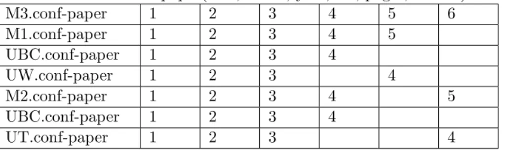
Since MTold and MTnew are both about “conf-paper”, they can be merged to be one MappingTable, shown in Figure 5.7.
Relation: M3.conf-paper(title, venue, year, url, pages, author)
M3.conf-paper 1 2 3 4 5 6 M1.conf-paper 1 2 3 4 5 UBC.conf-paper 1 2 3 4 UW.conf-paper 1 2 3 4 M2.conf-paper 1 2 3 4 5 UBC.conf-paper 1 2 3 4 UT.conf-paper 1 2 3 4
Figure 5.7: MappingTable for Example 12(b)
Both “UBC.conf-paper” in line 3 and 6 are kept for clarity. However, in real implementation and after optimization, only one of them needs to be kept.
5.3.2 Algorithm
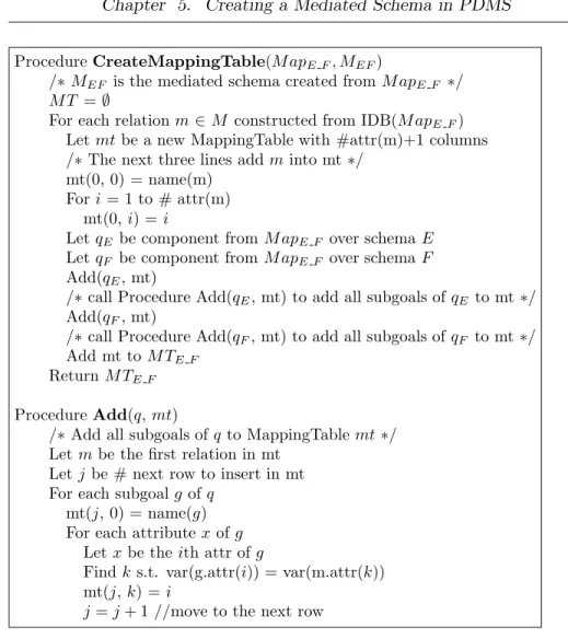
Figure 5.8 shows how to create a MappingTable for each relation that is constructed from a mappingM apE F in the mediated schema. Procedure createMediatedSchema(E, F, M apE F) in Figure 5.1 will first be called.
Chapter 5. Creating a Mediated Schema in PDMS
Given M apE F and MEF, the MappingTables will be constructed for each concept inM apE F.
When a peer have two different versions of mediated schemaM1 andM2
maintaining different information, if bothM1 and M2 contain conceptq, in
order to merger1 andr2, corresponding MappingTableM T1(q) andM T2(q)
needs to be merged. (r1 and r2 are the corresponding relations in M1 and M2 representing the concept q.)
The MappingTable merging process follows the same general principles: 1. Related attributes should be positioned in the same column;
2. Un-related attributes are in different columns;
3. Overlapping local relations in the two MappingTables are used to de-termine each column in one MappingTable corresponds to that in the other MappingTable.
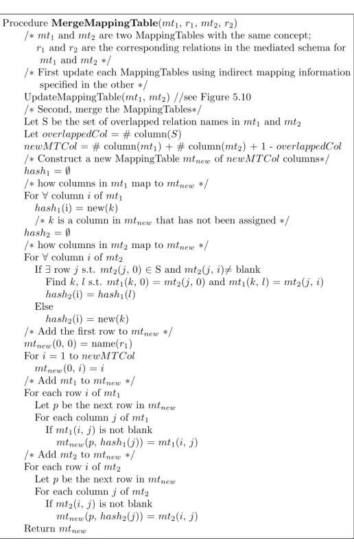
Procedure mergeMappingTable(mt1, r1, mt2, r2) in Figure 5.9 merges
any two MappingTable of the same concept mt1 and mt2, and returns a
merged MappingTable. It is required that there be overlapped relations in mt1 and mt2; otherwise, they cannot be merged. Since it is likely that
each MappingTable contains indirect mapping information that the other one does not have, the first step for merging two MappingTable is to update such information for each MappingTable shown in Figure 5.10.
5.3.3 Section Summary
In this section, we presented by examples the motivation of introducing a MappingTable for each relation in the mediated schema that comes from a mapping. We also discussed the case of merging two MappingTables. We further gave three algorithms that are related to operating MappingTables. They are creating a MappingTable, merging MappingTables and updat-ing current Mappupdat-ingTable usupdat-ing additional mappupdat-ing information in another MappingTable.
Chapter 5. Creating a Mediated Schema in PDMS
ProcedureCreateMappingTable(M apE F, MEF)
/∗MEF is the mediated schema created fromM apE F ∗/
M T =∅
For each relationm∈M constructed from IDB(M apE F) Letmtbe a new MappingTable with #attr(m)+1 columns /∗The next three lines addminto mt∗/
mt(0, 0) = name(m) Fori= 1 to # attr(m)
mt(0,i) = i
LetqE be component fromM apE F over schemaE LetqF be component from M apE F over schemaF Add(qE, mt)
/∗call Procedure Add(qE, mt) to add all subgoals ofqE to mt∗/ Add(qF, mt)
/∗call Procedure Add(qF, mt) to add all subgoals ofqF to mt∗/ Add mt toM TE F
ReturnM TE F ProcedureAdd(q,mt)
/∗Add all subgoals ofqto MappingTablemt∗/ Letmbe the first relation in mt
Letj be # next row to insert in mt For each subgoalgof q
mt(j, 0) = name(g) For each attributexofg
Letxbe theith attr ofg
Findk s.t. var(g.attr(i)) = var(m.attr(k)) mt(j, k) =i
j=j+ 1 //move to the next row
Figure 5.8: Create MappingTable Algorithm
5.4
Mapping Compatible Check
Two mappings that are created at different peers by different users might have the same IDB name, indicating that these two mappings represent the same concept. However, as is discussed in Section 4.2, two mappings having the same concept should follow Definition 3 (i.e. these two mappings should have the same IDB name, they have overlapped subgoal names and their overlapped subgoal sets are equivalent). The module of Mapping Compatible Check is to make sure that the mappings are really representing the same
Chapter 5. Creating a Mediated Schema in PDMS
ProcedureMergeMappingTable(mt1,r1,mt2,r2)
/∗mt1and mt2 are two MappingTables with the same concept;
r1 andr2are the corresponding relations in the mediated schema for
mt1 andmt2 ∗/
/∗First update each MappingTables using indirect mapping information specified in the other∗/
UpdateMappingTable(mt1, mt2) //see Figure 5.10
/∗Second, merge the MappingTables∗/
Let S be the set of overlapped relation names inmt1 andmt2
LetoverlappedCol= # column(S)
newM T Col= # column(mt1) + # column(mt2) + 1 -overlappedCol
/∗Construct a new MappingTablemtnewofnewM T Colcolumns∗/
hash1=∅
/∗how columns inmt1map tomtnew ∗/ For∀ columniofmt1
hash1(i) = new(k)
/∗kis a column in mtnew that has not been assigned∗/
hash2=∅
/∗how columns inmt2map tomtnew ∗/ For∀ columniofmt2
If∃rowj s.t. mt2(j, 0)∈S andmt2(j, i)6= blank
Findk,ls.t. mt1(k, 0) =mt2(j, 0) andmt1(k,l) =mt2(j, i)
hash2(i) =hash1(l)
Else
hash2(i) = new(k)
/∗Add the first row to mtnew ∗/
mtnew(0, 0) = name(r1)
Fori= 1 to newM T Col mtnew(0, i) =i
/∗Addmt1to mtnew ∗/ For each rowi ofmt1
Letpbe the next row inmtnew For each columnj ofmt1
Ifmt1(i,j) is not blank
mtnew(p,hash1(j)) =mt1(i, j)
/∗Addmt2to mtnew ∗/ For each rowi ofmt2
Letpbe the next row inmtnew For each columnj ofmt2
Ifmt2(i,j) is not blank
mtnew(p,hash2(j)) =mt2(i, j)
Returnmtnew
Chapter 5. Creating a Mediated Schema in PDMS
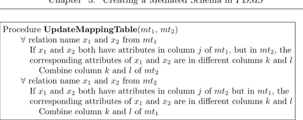
ProcedureUpdateMappingTable(mt1,mt2)
∀ relation namex1 andx2 frommt1
Ifx1 andx2 both have attributes in columnj ofmt1, but inmt2, the
corresponding attributes ofx1 andx2 are in different columnskand l
Combine columnkandl ofmt2
∀ relation namex1 andx2 frommt2
Ifx1 andx2 both have attributes in columnj ofmt2but inmt1, the
corresponding attributes ofx1 andx2 are in different columnskand l
Combine columnkandl ofmt1
Figure 5.10: Update MappingTable Algorithm
concept when merging the information contained by two mappings.
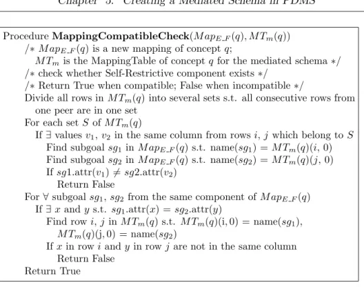
Since every peer only maintains its own mappings and does not know other peers’ mapping, the mapping compatible check needs to rely on the MappingTable that can infer the original mappings. The algorithm in Fig-ure 5.11 inputs the original MappingTable of concept q for the mediated schema, M Tm(q), and a new mapping of the concept q, M apE F(q). The algorithm first checks whether there exists a case when two attributes of a certain subgoal or two attributes of different subgoals in M apE F(q) have the same value but have different value in a previous mapping, which is rep-resented by a row or a set of rows inM Tm(q). The algorithm further checks if there exists a case when inM apE F(q), two attributes in one subgoal or in two subgoals from one component have the same value, but inM Tm(q), the corresponding attributes have different values. If either of the above case is true, the new mapping of concept q is not compatible with a previous existing mapping of concept q. The mapping needs to be modified by the user.
We assume that at least one subgoal should be in common if one schema is involved in several conjunctive mappings with the same IDB name.
5.5
Peer Schema Mediation
We have briefly described MePSys in Section 5.2. In this section, we de-scribe our Peer Schema Mediation algorithm (short for PSM algorithm), which is composed of three small algorithms, schema mediation, computing
![Figure 5.1: The CreateMediatedSchema Algorithm from [22]](https://thumb-us.123doks.com/thumbv2/123dok_us/9868486.2876622/35.918.189.717.133.538/figure-the-createmediatedschema-algorithm-from.webp)
![Figure 5.2: The CreateMapping Algorithm from [22]](https://thumb-us.123doks.com/thumbv2/123dok_us/9868486.2876622/36.918.185.711.131.558/figure-the-createmapping-algorithm-from.webp)