1355
0-7803-7651-X/03/$17.00 2003 IEEE
A Generic Framework for Robotic Navigation
Chris Urmson Reid Simmons Issa NesnasCarnegie Mellon University Carnegie Mellon University Jet Propulsion Laboratory 5000 Forbes Avenue 5000 Forbes Avenue California Institute of Technology
Pittsburgh, PA 15213 Pittsburgh, PA 15213 Pasadena, California 91109 412-268-3978 412-268-2621 818-354-4321 [email protected] [email protected] [email protected]
Abstract— This paper describes progress in the
development of a navigation framework for the Coupled-Layer Architecture for Robotic Autonomy (CLARAty). As part of CLARAty, the framework shares the goals of enabling code reuse while maintaining efficiency and accessibility. The framework is roughly divided into generic components along sense-think-act lines. A discussion of the role and structure of each component is presented. An illustrative example is presented of an implementation of a Morphin/D*-based navigation algorithm using this framework. Early results from experimentation in simulation are also presented.
TABLEOFCONTENTS ... 1.INTRODUCTION...1 2.NAVIGATION ARCHITECTURE...2 3.EXAMPLE IMPLEMENTATION...4 4.SUMMARY...7 REFERENCES...7
1.
I
NTRODUCTIONThis paper describes progress in the development of a navigation framework for the Coupled-Layer Architecture for Robotic Autonomy (CLARAty) [13]. As part of CLARAty, this framework shares the design goals of maximizing code reuse while maintaining an efficient and accessible implementation.
CLARAty is designed to ease the transition from research to flight-ready software. It attempts to achieve this goal by developing a set of standard interfaces and a basic set of reusable components. CLARAty is being developed using object-oriented design principles to enable code reuse and to provide an avenue for extension. An open source development model is being used to allow collaborators to contribute component extensions, which helps the architecture achieve and maintain a critical mass. A detailed discussion of the motivation for CLARAty can be found in [14].
One novel feature of the CLARAty architecture is its two layer structure, illustrated in Figure 1. The top level, or decision layer, provides a combination of procedural planner and operational executive. The lower level, or
functional layer, provides a hierarchical interface to hardware components and rover services. The decision layer may access services in the functional layer at any point in the hierarchy, allowing the decision layer to plan at a granularity appropriate for a given task.
The motivation for developing a generic navigation framework comes from our experiences implementing navigation algorithms for a variety of robots. For example, a combination of a local obstacle avoidance algorithm (Morphin) [9] and a real time path planner (D*) [11] has been used on a number of robotic platforms. A first implementation was developed for Ratler [5]. Since then, it has been used on a progression of robots including Nomad [15], an ATRV [10], and most recently Hyperion [12]. Each new implementation has made gains in performance and capabilities but a major effort has been required to port the software, often involving a complete reimplementation. A goal of this work is to simplify this process, allowing researchers to focus on developing and testing new capabilities rather than dealing with the mundane details of
Figure 1 - The relationship between the functional and decision layers in CLARAty.
creating a platform specific implementation of an existing algorithm.
We believe that the navigation framework described here will enable a large family of navigation algorithms to readily run on a variety of robotic platforms. This “write once, run anywhere” paradigm is a fundamental goal of CLARAty. Not only will the framework simplify development, it will also enable the direct comparison of algorithms in controlled experiments.
This framework has been developed by first analyzing the fundamental components of a variety of navigation algorithms. Then, through judicious design, a modular framework that is efficient, portable and easily extensible was developed. The framework breaks navigation algorithms into a set of decoupled components. Through this decomposition, gains are made in code reuse and maintainability. This decomposition is discussed in detail in the following section.
2.
N
AVIGATIONA
RCHITECTUREThe role of a navigation algorithm is to generate safe paths through terrain while achieving specific goals. The navigator uses sensor data to evaluate terrain and locomotion components to execute motor and robot trajectories.
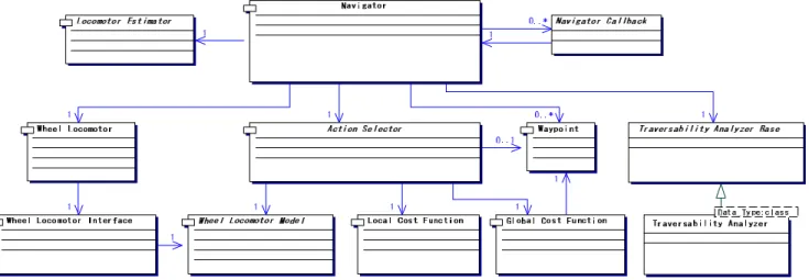
Our navigation architecture is divided into modules roughly along sense-think-act lines: traversability analysis, cost functions, and action selection. In the traversability
analysis components, sensor data is converted into a model
of the world. Cost functions transform these models into a form that can be used for planning. Action selectors then use this planning space to determine how the robot should move. Once a course of action is determined, the resulting trajectory is then passed to the locomotion system for execution. The navigator provides the basic interface
between decision layer processes and the navigation and locomotion systems. Figure 2 illustrates the relationship between the generic components of this framework. Each component provides a standardized set of interface functions that can be overridden in descendant classes to provide specific behavior.
Waypoints
Navigation goals are expressed as waypoints. Waypoints provide a simple interface that returns whether or not a state is in a set of desired states. The basic implementation is a two dimensional goal location specified with some error tolerance. Descendent waypoint classes may provide more complicated goal conditions, such as a goal line to cross or achieving a position with a desired orientation.
Navigator
The navigator tracks the progress of the robot as it progresses towards a waypoint. Through this interface, the
while (!done) { update pose execute callbacks if (cur_waypoint->achieved()) { if (!waypoint_queue->is_empty()) { cur = waypoint_queue->pop() } else { done = true } } else { traversability_analyzer->update() action = selector->get_best_action(); locomotor->execute(action) } }
Figure 3 - The navigation loop. Figure 2 – The structure of the navigation framework.
decision layer may queue a list of waypoints for the robot to pass through. The navigator also provides an interface through which callbacks can be registered. The callbacks can be used to monitor the progress of the navigator or, in a more complex way, to trigger non-navigation tasks to execute (e.g. opportunistic science). Figure 3 shows the basic sense-think-act loop that makes up the navigator’s execution loop.
Traversability Analysis
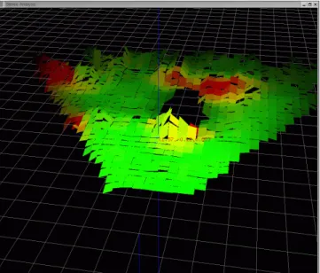
Traversability analysis involves the conversion of sensor data into a model of the world. This may be as simple as a binary occupancy grid or as complicated as a statistical evaluation of the terrain (illustrated in Figure 4).
The decoupling of terrain analysis from the details of the navigation algorithm allows for a straightforward interchange of sensors and processing techniques without changing the underlying approach used to select actions. The traversability analyzer class provides a simple hook to trigger this analysis. Objects that require terrain information register with the traversability analyzer; when data becomes available (e.g. the sensors have been sampled and the terrain analysis has been performed) each registered object has its callback function executed. By using a publish/subscribe paradigm in this way, information can flow to classes outside of the navigation subsystem (i.e. for monitoring or map building) while unnecessary interfaces are not forced upon classes that do not need traversability data. Furthermore, the sensor update rate can be decoupled from the navigation rate, within the constraints imposed by the sensor footprint and speed of the robot [4].
Cost Functions
Cost functions transform the terrain evaluation data into a form that can be used for planning. They are divided into two types: local and global. Local cost functions return the instantaneous cost for traversing a particular patch of terrain. Global cost functions provide the estimated cost to reach a goal from a particular location. This division is based on the assumption that, in the large scale, robot motion can be approximated as holonomic, while locally there are a variety of constraints that limit the motion of a robot. Both types of cost functions provide a cost per unit distance scale factor to allow them to be weighted appropriately.
Local cost functions may simply return a binary cost stating whether a location is traversable or they may use the output of a complicated traversability analyzer to provide a continuous cost measure. Similarly, global cost functions may be as simple as the distance to the goal or may be as complicated as the cost to go returned by an information optimal planner. By combing these two types of cost
functions, the local minima problems associated with purely local path planners can be avoided.
Action Selection
The action selector class is where the specifics of a navigation algorithm are implemented. Fundamentally, the role of the action selector is to determine the appropriate next action(s) for the robot to perform given its current state and information from local and global cost functions. Through the decoupling of action selection from traversability analysis, it is straightforward to modify the set of trajectories over which the navigation algorithm searches (for example searching arcs instead of point-turn/straight line paths). The generic action selector interface provides accessor functions to get and set the current waypoint, and a function that returns the next action the robot should take. To enable a generic implementation of algorithms, action selectors are provided with a model of the locomotion capabilities of the rover. At minimum, the model provides a kinematic projection of trajectories and important kinematic properties, such as the number of wheels and the wheelbase of the robot. Action selectors may use this information to generically integrate terrain costs over the expected path of a robot.
Locomotion
The locomotor classes provide an abstract interface to the underlying robotic locomotion mechanism. The locomotion framework is structured in a double-bridge software pattern [2], allowing independent specialization of the kinematic configuration and control interface. The
wheel locomotor class provides the interface used by other
Figure 4 - Representation of a statistical evaluation of terrain.
components to maneuver the vehicle. The wheel locomotor
interface defines functions that descendants must provide
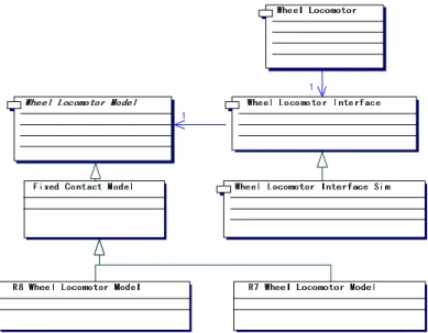
to encapsulate the specifics of the protocol used to command the mechanism. The wheel locomotor model describes the kinematics of the robot. This structure allows for maximal code reuse, which is particularly important in a research environment where changes to the robot may occur incrementally, e.g. the control system may be redeveloped while the mechanical robot remains the same, or vice versa. Figure 5 illustrates this structure.
Locomotor interface classes provide an abstraction to the different control interfaces potentially available on a robot (e.g. independent motor control, bank control, high level arc control). Drive commands are used as a high level interface to the locomotor. Each command encodes one of six basic motions a mobile robot can perform (see Figure 6). An instantiation of the locomotor uses its associated interface class to convert the given drive commands into a set of low-level motor commands.
Information about the kinematic properties of the robot is provided through the same locomotion model that is used in the action selector. By maintaining this information in a single location, the possibility of a mismatch between the navigation and locomotion systems is eliminated, allowing a robust decoupling of the generation of robot level motion commands and individual motor control commands.
Framework Implementation
As with all parts of CLARAty, the navigation framework is designed to operate on a variety of software and hardware platforms. Operating system support includes various flavors of Linux, VxWorks, and Solaris. The navigation framework also operates on both Intel and Motorola processors. To simplify the task of developing for multiple platforms, the Adaptive Communication Environment (ACE) [7] is used as a hardware and operating system abstraction layer. ACE provides operating system independent implementations of a variety of common programming constructs including mutexes, threads, and inter-process communication structures. Through the use
of ACE, porting the framework to other operating systems (e.g. QNX) should be straightforward.
3.
E
XAMPLEI
MPLEMENTATIONTo demonstrate the use of the framework, an example implementation of a navigation architecture that utilizes both local and global knowledge to traverse unknown terrain is now presented. This implementation is being used to operate a variety of simulated and real rovers, both at Carnegie Mellon University and at NASA.
Prior implementations of this navigation algorithm [5][10][12] were closely tied to the robot for which they were developed. With each new robot, the software would generally need to be reimplemented to provide modifications to allow it to run on a specific platform. For example, in each module the arcs selected for evaluation implicitly encode a model of how the vehicle moves. Furthermore, since each version of the navigation software was implemented for a different robot with different capabilities, it was difficult to directly compare the
Figure 5 - The double-bridge structure of the locomotion framework.
Figure 6 - Six basic motions (A) idle, (B) turn in place, (C) drive straight, (D) drive along an arc, (E) crab in an arbitrary direction, and (F) crab along an arc.
performance of these algorithms.
Terrain Analysis
The Morphin algorithm [9] is used to perform terrain analysis. It operates by generating statistical metrics of the terrain from range data. To do this, the local terrain is divided into cells. Groups of cells are combined into overlapping robot-sized patches. For each patch the algorithm finds the best plane that represents the perceived terrain (see Figure 4).
Traversability is determined by analyzing three metrics: slope, roughness, and “step height”. Each metric is normalized so that they can be compared directly. The traversability of a patch is determined by the worst of the three values.
In general, regions of the sensor footprint that contain more data points generate better estimates of the actual terrain. To encode this, a certainty value is computed for each patch. Certainty is calculated as a function of the number of points in a patch and the evenness of the distribution of the points over the patch.
Cost Functions
The traversability map generated by Morphin is used directly as the local cost function. The cost returned is calculated as the inverse of the traversability score multiplied by the certainty of the data in a cell.
Dynamic A* (D*)[11] is used to provide information-optimal global costs. D* generates an initial cost map from available a priori information and then modifies the map as new terrain analysis data becomes available. The advantage of D* over basic A*-like algorithms is that it replans in regions of the space that are affected by new information, rather than replanning over the entire space. This provides a significant performance advantage, particularly in the case of mobile robotics where new information about the world is localized due to the nature of the sensors used.
Action Selection
In this implementation, the action selector chooses among a set of forward and backward arcs. The action selector utilizes data from both the Morphin local cost evaluation and the D* global cost function to determine the best trajectory to execute.
Prior Implementations
In prior implementations, the navigation system was not decomposed along the lines described here. Morphin and D* independently determined costs for each arc the robot could traverse. Morphin would attempt to avoid difficult terrain in the local sensor map, while D* would try to minimize the distance to a goal. These “votes” were then either summed or passed through an arbitration system. The combined lowest cost arc was then selected for execution.
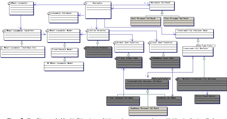
Figure 7 - Class Diagram of a Morphin/D* navigator. Light grey boxes represent classes added for visualization. Dark grey boxes represent classes that were added to extend the navigation framework for this navigator.
The capabilities of a robot were also implicitly encoded in each algorithm, which decreased the reusability of developed components. The functionality of the action selector was also distributed to both algorithms, requiring independent implementations of models to predict the outcome of executing various arcs. Since the action selector was encoded within each algorithm, modifying the types of trajectories executed by a robot was difficult.
Navigation Framework Based Implementation
To address these problems, Morphin and D* were ported to the navigation framework discussed in this paper. Figure 7 shows the resulting structure of the software. The Morphin algorithm provides traversability data to the navigation system through the callback interface described earlier. Three classes register to receive this data:
• Goodness Callback: this class updates a local traversability map used as a local cost function. • D* Goodness Callback: this class transfers the
traversability analysis to the map used by the D* global cost function.
• Goodness Streamer Callback: a debugging class which is used to broadcast this data to an off board user interface.
The local and global cost functions are used by an implementation of the action selector interface which searches for the best arc to traverse.
This framework addresses many of the problems associated with prior implementations of the algorithms. In this framework, the model used to describe the motion of the robot is centralized, so all cost evaluations are consistent. Furthermore, the scaling data in the cost functions allows for arbitrary cost functions to be used while still providing
reasonable summations.
Within the framework, each component (e.g. the action selector, Morphin traversability analyzer, D* cost function, and locomotion model) is independent of the others. Changing the types of motion the robot performs therefore does not require changes to any module other than the action selector. For example, to have a robot move along straight line segments connected by point turns would require only the implementation of a new action selector. Similarly, by replacing the Morphin traversability analyzer with a port of the GESTALT terrain analyzer [3], the two traversability analyzers could be compared directly, without the need to change other software.
The fundamental nature of the algorithm can also be easily changed. For example, by removing the D* global cost function and replacing the action selector with a new module, a new navigation system that resembles the Rover Bug [6] algorithm could be quickly implemented.
Results
This implementation has been tested in simulation and is currently undergoing testing in the JPL Marsyard. As described earlier, the framework operates on both VxWorks and Linux and on both Intel and Motorola processors. Through the use of an appropriate locomotion model and interface, the navigator operates on both Rocky 7 and Rocky 8, as well as with a generic rover in simulation. Though more general, the new implementation appears to be approximately as efficient as the original implementation. Timing results show that the navigation loop, excluding the time required to perform stereo vision, executes in under 0.1s on a 900Mhz Pentium III. This is approximately the same amount of computation time as required by the most recent prior implementation.
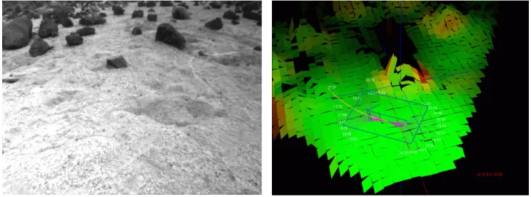
Figure 8 - Navigation camera image and visualization tool showing Morphin terrain analysis and action selection for an arbitrary pose in the scene.
To evaluate and debug our new implementation, the visualization tool shown in Figure 8 was developed. It is used to perform traversability analysis on recorded images, and to test the behavior of an action selector given the traversability analysis. In previous implementations, a similar tool was developed to evaluate the traversability analysis, but it was not possible to visualize the action selection process. Using components from the new framework, the tool was straightforward to develop and provides the enhanced ability of rendering the reasoning being performed by the action selector.
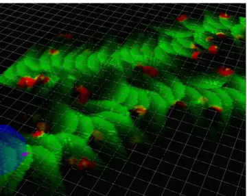
In simulation, the navigation software has repeatedly driven the robot between waypoints spaced approximately 40m apart. Figure 9 shows a composite navigation map generated as the robot traveled through two consecutive waypoints. The first waypoint was located to the right of the image; the second is represented by the blue hemisphere.
True to its goal, this implementation of the navigation algorithm can be directly utilized on a variety of robotic platforms. The core navigation software requires no changes to transfer it between platforms. The only software that differs between various platforms is the wheel locomotor model, wheel locomotor interface and the software used to generate range data. These changes are localized, and the required components can be used across a variety of other navigation algorithms.
4.
S
UMMARYThe navigation framework presented in this paper provides a generic approach to implementing algorithms so that they may operate on a variety of robotic platforms. The framework defines a set of basic interfaces and callback hooks that provide broad flexibility in the algorithms that can be implemented.
Most navigation approaches fit well within this framework, though some, such as the Fuzzy Logic navigator [8] would likely not benefit from the reuse of many of the components described in example implementation. Other completely reactive approaches, such as the subsumption architecture [1], do not fit well within this framework. That being said, a large family of navigation algorithms can be implemented using this framework, and will greatly benefit from reusing available and robust components.
In the near future we intend to more thoroughly test and evaluate our current navigation implementation. Within the next year we intend to implement both the Rover Bug [6] and GESTALT [3] algorithms within this framework and compare them in controlled experiments.
Acknowledgments
This paper describes work contributed by the entire CLARAty team at CMU, NASA Ames and the Jet Propulsion Laboratory. The authors would like to particularly acknowledge and thank Max Bajracharya, Kam Lasater, Eric Leese, and Andy Yang for their contributions. This work is supported by NASA under contract #1229340.
R
EFERENCES[1] R. Brooks “Elephants Don’t Play Chess”, Robotics and
Autonomous Systems, No 6, 1990.
[2] E. Gamma et al., “Design Patterns: Elements of Reusable Object-Oriented Software”, Reading, Mass: Addison- Wesley, 1995.
[3] S. Goldberg et al., “Stereo Vision and Rover Navigation Software for Planetary Exploration”, Proc.
IEEE Aerospace Conference, March 2002.
[4] A. Kelley and A. Stentz. “Rough Terrain Autonomous Mobility – Part 1: A Theoretical Analysis of Requirements”, Autonomous Robots, May 1998, pp 129-161
[5] E. Krotkov et. al., “Evolution of a Prototype Lunar Rover: Addition to Laser-Based Hazard Detection, and Results from Field Trials in Lunar Analogue Terrain”,
Autonomous Robots, July, 1997
[6] S. Laubach and J. Burdick. “An Autonomous Sensor-Based Path-Planner for Planetary Microrovers”, Proc. IEEE
International Conference on Robotics and Automation,
Detroit, USA, May 1999.
[7] D. Schmidt, “An Architectural Overview of the ACE Framework: A Case-study of Successful Cross-platform Systems Software Reuse”. USENIX login magazine,
Tools special issue, November, 1998.
[8] H. Seraji et al. “Safe Navigation on Hazardous Terrain”, Proc. IEEE International Conference on Robotics
and Automation, Seoul, Korea, May 2001.
Figure 9 - An example composite navigation map generated during a simulation experiment.
[9] R. Simmons et al., “Experience with Rover Navigation for Lunar-Like Terrains”, Proc. Conference on Intelligent
Robots and Systems, Pittsburgh PA, August 1995.
[10] S. Singh et al. “Recent Progress in Local and Global Traversability for Planetary Rovers”, Proc. IEEE
International Conference on Robotics and Automation, San
Francisco, USA, April 2000.
[11] A. Stentz. “Optimal and Efficient Path Planning for Partially-Known Environments”, Proc. of IEEE International Conference on Robotics and Automation,
volume 4, pp.3310-3317, 1994.
[12] C. Urmson, et al., “Stereo Vision Based Navigation for Sun-Synchronous Exploration”, Proc. of IEEE/RSJ Conference on Intelligent Robots and Systems, October
2002.
[13] R. Volpe, et al., "The CLARAty Architecture for Robotic Autonomy." Proceedings of the 2001 IEEE
Aerospace Conference, Big Sky Montana, March 10-17
2001.
[14] R. Volpe, et al., "CLARAty: Coupled Layer Architecture for Robotic Autonomy." JPL Technical Report
D-19975, Dec 2000.
[15] D. Wettergreen et al. “Developing Nomad for Robotic Exploration of the Atacama Desert”, Robotics and
Autonomous Systems, February 1999.
Chris Urmson is a Ph.D. student at
Carnegie Mellon University. He earned his B.Sc. from the University of Manitoba. While at Carnegie Mellon, he has been involved with the development of a variety of space and terrestrial robots. His current research focuses on the development of a real time dynamical constraint cognizant planner for outdoor mobile robots.
Reid Simmons is a Principal Research
Scientist in the School of Computer Science at Carnegie Mellon University. His research focuses on developing self-reliant robots that can autonomously operate over extended periods of time in unknown, unstructured environments. This work involves issues of robot
control architectures that combine deliberative and reactive control, probabilistic planning and reasoning, autonomous indoor and outdoor sensor-based navigation, and robust error detection and recovery. Dr. Simmons has been involved in the development of over a dozen autonomous robots, and was part of the Remote Agent team that won the 1999 NASA Software of the Year Award.
Issa A.D. Nesnas, Ph.D. is the Task
Manager for the Architecture and Autonomy Research collaborative task. His research interests include software and hardware architectures for robotic systems and sensor-based robot control. Issa received a B.E. degree in Electrical Engineering from Manhattan College,
NY, in 1991. He earned the M.S. and Ph.D. degrees in Mechanical Engineering from the University of Notre Dame, IN, in 1993 and 1995 respectively. In 1995, he joined Adept Technology Inc. as a senior project engineer. He has joined NASA at the Jet Propulsion Laboratory in 1997. At JPL he has worked on several robotic and flight projects researching autonomous sensor-based systems. He has received several Notable Organizational Value Added (NOVA) Awards and an Exceptional Achievement Award for his work at JPL. Issa holds a patent for the Impulse-based flexible parts feeder and is a member of Eta Kappa Nu and Tau Beta Pi National Honor Societies.