KF Series
Liquid Level Indicating Controller
Model KFLB
OVERVIEW
The KF Series instruments are field-mounted
type pneumatic indicating controllers which are
used to measure and control various types of
process variables such as temperature, pressure,
flow and liquid level.
Indicating transmitters and indicating controllers
with transmitters are also available as well as
indicating controllers. The controllers are
avail-able either in a local type to set the set-point
value manually with a knob on the instrument or
in a cascade type (remote type) to set the
set-point value with a pneumatic set-set-point signal.
Model KFLB Liquid Level Indicating
Control-lers are displacement type instruments for the
measurement and control of such process
vari-ables as liquid levels, boundary surfaces, and
specific gravities.
FEATURES
• A wide variety of elements materials and
con-trol mechanisms are available to meet various
applications.
• The unit has a pneumatic circuit board and a
sturdy, heat-resistant weatherproof case,
thereby greatly improving durability and
reli-ability.
• The pneumatic circuit board system allows the
user to readily add or eliminate control
mecha-nisms and units, thereby enhancing system
modification and expansion flexibility.
• Interchangeable parts are used to the maximum
practical extent, thereby reducing the number
of spare parts to be kept in stock.
• Able to cover wide ranges of temperatures,
pressure, and specific gravities.
APPLICATIONS
• To a level measurement of the reaction, the
dis-tillation, the drying and the recovery unit.
• Boundary surfaces and specific gravity
mea-surement.
• To the measurement in the cryogenic services
(liquefied gas etc. of min. -196
°
C) and high
temperature (max. +400
°
C) services.
• To the measurement in high vacuum (min.
-101.3 kPa) and high pressure (max. 15 MPa)
services.
STANDARD SPECIFICATIONS
Range of standard measuring setting range
Specific-gravity
1. Use as level instrument, 0.1 to 1.6 in specific gravity. 2. Use as boundary surface are as following.
If the specific gravity of upper layer liquid is γ2, the lower layer liquid one is γ3, it becomes γ2<γ3, 0.4<γ2, γ3<1.6, and 0.1<γ3-γ2<1.2
Please refer to Table 1.
Table 1 Specific-gravity (0.1 to 1.6)
Medium specific gravity:
It is possible to correspond to JIS 63K or ANSI / JPI 600 as standard.
Low specific gravity:
It is possible to correspond to JIS 30K or ANSI / JPI 300 as standard.
Please consult to our sales, except for the above-men-tioned.
Please refer to Table 2 for details.
Working pressure range
It is possible to use from -101.3 kPa up to each flange pressure rating.
(Maximum JIS63K or ANSI/JPI600#), for ANSI/JPI900# is also available with some condition.
Process connection
Flange connectionsExternal chamber type
Connection Side-side flanged, SIde-bottom flanged, Top-side flanged, Top-bottom flanged Flange size 2 inches or 1½ inch RF,
2 inches or 1½ inch RTJ (for ANSI / JPI 600#)
Internal float type
Connection
Top flanged
Flange size
3 inches RF, 4 inches RF, 5 inches RF, 3 inches or 1½ inch RTJ (for ANSI / JPI 600#)
Materials
Refer to “Table 3 Material” on page 3
Meter specification
Refer to “Table 4 Meter specification” on page 3
Mounting
Direct mount to the process with flanges
Weight
Approx. 45 kg. Range (mm) Range of measuring setting range (mm)
0 - 300 Set applicable within left side range. 0 - 350 0 - 400 0 - 450 0 - 500 0 - 600 0 - 700 0 - 800 0 - 1000 0 - 1200 0 - 1500 0 - 2000 300 500 700 2000 1.6 0.6 0.4 0.2 0.15 0.1 Max range (mm) Medium Low Medium Low Medium Low Sp. Gr.
Table 2 Float test pressure (Material: SUS316L)
Model Measuring range (mm)
Medium specific gravity (KFLB_ - 61) Low specific gravity (KFLB_ - 62) Float diameter (mm) Over load pressure (MPa) Flange pressure rating float diameter Float diameter (mm) Over load pressure (MPa) Flange pressure rating float diameter 03 0-300 55
15.0 Max. JIS63K, ANSI/JPI600
95 7.8 Max. JIS30K, ANSI/JPI300
A3 0-350 04 0-400 A4 0-450 05 0-500 06 0-600 45 85
3.2 Max. JIS10K, ANSI/JPI150
07 0-700 08 0-800 10 0-1000 12 0-1200 30 65 15 0-1500 20 0-2000 55
Float weight: 3 kg (Medium specific gravity type)
(The weight difference depending on the specific gravity in case of the medium specific gravity type and the low spe-cific gravity type in boundary surface meter as the spespe-cific gravity measurement type.)
Note) *1 The maximum temperature is available up to 200°C. *2 If the optional code is “D”, it is not selectable carbon steel.
Table 3 Material
Model (temp. range) Parts
U M A E D
(350 to 400°C) (200 to 350°C) (0 to 200°C) (0 to 200°C) (-196 to 0°C)*1
Torque tube Inconel Inconel Inconel SUS316L SUS316L
Bonnet / Chamber Carbon steel (SFVC2A), SUS304, SUS316, SUS316L *2
Float SUS316L
Bolts Chromium-molybdenum steel (SNB7) SUS304
Gasket Spiral type (semi-metallic, filler material: asbestos)
Radiating fins Provided Non provided
Table 4 Meter specification
Item Specification
Indicator section Indicating angle 44 deg.
Scale length 150 mm
Pointers PV: Red, SV: Green
Output gauge Scale: 0 to 200 kPa, Indicating accuracy: ± 3% F.S.
Setting section Local setting Internal or external setting with a setting dial.
Remote setting With pneumatic signal of 20 to 100 kPa
Setting range 0 to 100% F.S.
Controller section Control actions P + Manual reset, PI, PID, PD + Manual reset, PI + Batch, on-off, Differential gap, P + External reset, PD + External reset
Proportional band (P) 5 to 500% (Direct or reverse action)
Internal time (I) 0.05 to 30 min.
Derivative time (D) 0.05 to 30 min.
Differential gap 1 to 100% F.S., adjustable
Batch setting pressure 60 to 110 kPa, adjustable External reset pressure 20 to 110 kPa, adjustable
Manual reset pressure 0 to 100% F.S., adjustable (by pneumatic pressure setting) Standard
specifi-cation
Output 20 to 100 kPa, 0 or corresponding to supply air pressure (on-off, differential gap)
Minimum load I.D. 4 mm × 3 m + 20 cm2
Supply air pressure 140 ±14 kPa
Air consumption (50% output balanced)
Indicating transmitter: 5 l/min (N) Indication only: 5 l/min (N) Indicating controller: 5 l/min (N) Indication only: 5 l/min (N) Indicating transmitting and controller:9 l/min (N)
Saturated air supply capacity
Transmitter output: 40 l/min (N), Controller output: 40 l/min (N), Manual control output: 30 l/min (N)
Air piping connections Rc1/4 (PT1/4 internal thread) or 1/4NPT internal thread Ambient temperature -30 to +80C, refer to Table 5.
Relative humidity 10 to 90% RH
Case and door Enclosure: Waterproof and dust tight, meets JIS F8001 class 3 splash-proof,
NEMA3, IEC IP54
Material: Case ... Diecast aluminum Door... Polyester with fiberglass Door-glass . Reinforced glass (3 mm thick)
Case finish: Baked acrylic finish (for corrosion-resistant or silver finish, refer to “Optional specifications”)
PERFORMANCE
Standard characteristic
(within the range of specific gravity in Table 1, under standard operating condition)Transmission accuracy : ± 0.5% F.S.
Indication accuracy : ± 1.0% F.S.
Repeatability : 0.3% F.S.
Dead Band : ± 0.1% F.S.
Optional specifications
Internal manual loader (with auto/manual
transfer switch)
Consists of a manual control regulator, a two-position transfer switch and a balance check button.
With external manual SP setting knob
A setting knob is mounted on the door. SP can be adjusted externally.
Water and oil free treatment (Only the SUS
material) Range 1000 mm or less
Remove the moisture and the oil from the wetted part.
Oil free treatment (Only the SUS material)
Range 1000 mm or less
Remove the oil from the wetted part.
Test report
The result of visual checks and input output characteristics etc. for test (three points) of the level instrument is described and submitted.
Five point check
The measuring point of input output characteristics described to the test report is changed from 3 points (0, 50, 100%) to 5 points (0, 25, 50, 75, 100%).
Mil sheet
Test result of the chemical composition, the heat treatment condition, and the mechanical property of the element material (torque tube housing, bonnet, and chamber) with charge number of material is submitted.
With air set
Regulator with the filter + φ 40 pressure gauge is supplied. (Supply pressure; 200 to 970 kPa, output 140 kPa and pressure gauge; 0 to 200 kPa)
Dye check
The result of testing for the penetrant inspection in the weld of the element material (bonnet and chamber) is sub-mitted.
Without Float
The float is not supplied. Please specify if the existing float of our company KQP 1 , or KFL 00 - 1, or NQP31 or NQP21 is reused.
Without chamber
The chamber is not supplied. Please specify if the existing chamber of our company KQP 1 , or KFL 00 - 1, or NQP31 or NQP21 is reused.
Optional semi-standard and
spe-cial specifications
Stainless steel bolts
(Y131)SUS304 bolts are used for the main body assembling. The connection standard based on High-pressure gas regu-lation goods with JIS10K, ANSI150, and JPI150 it becomes a special requirement. Please consult to our sales.
Corrosion-prevention and silver painting
(Y138)Prevent corrosion (acrylic baking) finishing (Y138A)
Resistant against corrosive atmosphere
Preventive corrosion resistant (epoxy baking) finishing (Y138B)
Resistant against corrosive liquid.
Silver general (acrylic baking) finish (Y138C)
Resistant of heating up of equipment by direct sunshine or radiant heat.
Silver preventive corrosion (acrylic baking) fin-ishing (Y138D)
Protection of heating up of equipment and corrosive atmosphere.
Note) The silver finishing is not suitable for alkaline atmosphere.
Table 5 Operating temperature range (°C)
Standard operating range Normal operating range Limit operating range Transportat ion storing range Ambient tem-perature 23 ±2 -30 to 80 -40 to 85 -40 to 85 Liquid tem-perature 23 ±2 -196 to 400 -196 to 400 -40 to 85 (Other materials: U, M) (Other materials: A, E, D)
With radiation fin Without radiation fin
(Other materials: U, M) (Other materials: A, E, D)
With radiation fin Without radiation fin
Liquid t emper atur e ( C) Ambient temperature ( C) Liquid t emper atur e ( C) Ambient temperature ( C) (-30, -30) (-30, -30) (0, -196) (0, -196)
Level measurement except for boiler Level measurement for boiler and boundary surface measurement
ATTENTION
Attention in usage
• In the following cases, our standard displacement type level instrument might be unsuitable to the usage because it produces i t with measuring range = float length H. 0% or around 100% levels are detected in the normal operation. When output signals are the continu-ous output signals of 4mA or less or 20mA or more. • Set the float bottom to the zero point when you execute
the actual liquid adjustment after the displacement type level instrument is installed at the job site. The output change doesn’t generate if the measurement fluid does not contact with the float on the structure of the instru-ment.
Might it cause in the lower limit or the upper limit of the measuring range when setting it to the zero point exclud-ing the float bottom and trouble be caused in the mea-surement dead-band or characteristic of the linearity.
An appropriate adjusting method: Set the float bottom to the zero point.
An improper adjusting method: Set it to the zero point excluding the float bottm.
Attention in installation
Zero point Measuring range Float full length H Zero point Measuring range Measurement dead-band Zero point Measuring range Measurement dead-bandWARNING
• When install it, the gasket of process connection is required to set without rum off the edge.
• It causes a liquid leakage and the output error. Please do not use it excluding pressure, the temperature, and connected standard for which this specification sheet specified. It might cause a big accident because of damage and a liquid leakage.
CAUTION
• Please do not use this instrument for the work stand etc. after install it. The equipment might be damaged and it causes the injury.
• Please do not appropriate the tool etc. to the glass part of the display. It is likely to injure damaging the glass. • Please set it up correctly. When the installation is
insufficient, it might violate the output error and the corresponding rule.
• Because this instrument is a heavy lift, the work stand is noted, and the safety shoe is worn. Please do and do the installation operation.
Ordering information
1) Model number (At the specific gravity measure-ment... 'Z' is filled in on a basic model number end.) 2) Name of gas, liquid name, and type of gas, design
temperatures, and pressures (Especially, for the High pressure gas recognition equipment.)
3) Specific gravity, pressure, and temperature of liquid 4) Dimension to the upper part of float lower side of the
flange (L1) mm
5) The specific gravity measurement (range of specific gravity)
6) For the boundary surface measurement (specific gravity of upper layer liquid and lower liquid) 7) Optional specification
MODEL SELECTION
Model KFL__ - I II III - IV V VI VII VIII IX X XI XII XIII XIV - Options *9
Basic model no. *7 Selections Options
Note) *1~10: refer to next page.
KFL -
-Model Torque tube KFL X No options
Function Indicating transmitter B 0 M Internal manual loader (with A/M switch) Indicating controller (local type) B 1 K With external manual SP setting knob
Indicating transmitter and controller (local type) B 2 4 Water and oil free treatment (only the
SUS material) Range 1000 mm or less Indicating controller (cascade type) B 3
Indicating transmitter and controller (cascade type) B 4 5 Oil free treatment (only the SUS
materi-als) Range 1000 mm or less
No selection 0
P + Manual reset 1 6 Test report *10
PI 2 7 Five point check *10
PID 3 8 Mil sheet
PD + Manual reset 4 9 With air set
PI + Batch 5 B Dye check
On-Off 6 C Without float *5
Differential gap 7 D Without chamber *6
P + External reset 8
PD + External reset 9
Specific
gravity For medium specific gravityFor low specific gravity *1 6 16 2 Range of standard measuring setting range (mm) 0 - 300 (0.2 < low sp.gr. < 0.6, 0.6 < medium sp.gr. < 1.6) 0 3 0 - 350 (0.2 < low sp.gr. < 0.6, 0.6 < medium sp.gr. < 1.6) A 3 0 - 400 (0.2 < low sp.gr. < 0.6, 0.6 < medium sp.gr. < 1.6) 0 4 0 - 450 (0.2 < low sp.gr. < 0.6, 0.6 < medium sp.gr. < 1.6) A 4 0 - 500 (0.15 < low sp.gr. < 0.4, 0.4 < medium sp.gr. < 1.6) 0 5 0 - 600 (0.15 < low sp.gr. < 0.4, 0.4 < medium sp.gr. < 1.6) 0 6 0 - 700 (0.1 < low sp.gr. < 0.4, 0.4 < medium sp.gr. < 1.6) 0 7 0 - 800 (0.1 < low sp.gr. < 0.4, 0.4 < medium sp.gr. < 1.6) 0 8 0 - 1000 (0.1 < low sp.gr. < 0.4, 0.4 < medium sp.gr. < 1.6) 1 0 0 - 1200 (0.1 < low sp.gr. < 0.4, 0.4 < medium sp.gr. < 1.6) 1 2 0 - 1500 (0.1 < low sp.gr. <0.4, 0.4 < medium sp.gr. < 1.6) 1 5 0 - 2000 (0.1 < low sp.gr. < 0.4, 0.4 < medium sp.gr. < 1.6) 2 0 Other X X Process
con-nection External chamber type, side-side flanged (S-S)External chamber type, side-bottom flanged (S-B) 12 External chamber type, top-bottom flanged (T-B) 3 External chamber type, top-side flanged (T-S) 4 Internal float type, top flanged (T) L1 dimensions must be specified. 5
Other X
Element
materials Bonnet / Chamber (B & C)Carbon steel Torque tube housing (TH)Carbon steel 1
SUS304 SCS13A 2 SUS316 SCS14A 3 SUS316L SCS16A 4 Other X Other materi-als *3 (Tempera-ture range *2)
Torque tube: Inconel (350 to 400°C) (with radiation fin) U Torque tube: Inconel (200 to 350°C) (with radiation fin) M
Torque tube: Inconel (0 to 200°C) A
Torque tube: SUS316L (0 to 200°C) E
Torque tube: SUS316L (-196 to 0°C) *2 D
Other X Working pressure range *8 JIS 10K 1 JIS 20K 2 JIS 30K 3 JIS 63K 4 ANSI 150 (RF smoothness) A ANSI 150 (RF serration) B ANSI 300 (RF smoothness) C ANSI 300 (RF serration) D ANSI 600 (RF smoothness) E ANSI 600 (RTJ) F JPI 150 G JPI 300 H JPI 600 J JPI 600 (RTJ) K Other *4 X
Flange size 1½ inch (40 mm) (Applicable to external chamber type) 1 2 inches (50 mm) (Applicable to external chamber type) 2 3 inches (80 mm) (Applicable to internal chamber type) (only medium specific gravity) 3 4 inches (100 mm) (Applicable to internal chamber type) 4 5 inches (125 mm) (Applicable to internal chamber type) (only low specific gravity) *1 5
Other X
Air piping
connections Rc1/4 (PT1/4 internal thread) (Nameplate: Japanese)1/4NPT internal thread (Nameplate: English) AB Unit /
Pneu-matic signal kgf/cm2/ 0.2-1 kgf/cm2 PSI/ 3-15 PSI 12
bar/ 0.2-1.0 bar 3
Pa/ 20-100 kPa 4
Note
*1) Pressure rating “4”, “E”, “F”, “J”, and “K” cannot be selected for 5 inches/125 mm or the low density. *2) When other material is “D”
1
Even 0-200°C can be used.
2 The element materials “1” cannot be selected. *3) The float material is as follows.
Bolt/nut material is as follows.
Note)* If Y131 is specified, bolt/nut material of the sign * is changeable to SUS304/SUS304.
*4) Class900 is required consultation with our sales. Class1500 or more cannot be produced.
*5) Please specify the float model number if reusing an existing Yamatake float, model NQI, KFLB, KQP, or NQP. Please note the following:
1The selectable precondition as optional specification “C” for the existing product, “liquid level measurement specifica-tion: medium specific gravity”. Model number shall be NQI31 , NQI21 , KQP 1 , KFL 00- 1, NQP31 or NQP21 without Z.
2Note that the existing float diameter smaller than the stan-dard specification
3Please confirm the dimensions of the existing float, and confirm the accuracy of measurement using the following formula.
• Characteristics of the standard model KFLB
Note) *This accuracy table is common for all KFLB models regardless of liquid level measurement, interface measure-ment or gravity measuremeasure-ment specifications.
• Formula for checking accuracy
(g) Where D: Float diameter (mm)
H: Measuring range (float length, mm)
γ: Specific gravity
ρstd: Standard density, ρstd = 1 (g/cm3)
π: Circular constant
• Reference: Formula for Genesis buoyant by float Where ρ: Density of the ambient fluid (measuring
fluid)
V: Volume of the ambient fluid (measuring fluid) which the float displaced
G: Gravitational acceleration
Mf: Weight of the measuring fluid, which is dis-placed by the float
*6) Please specify the existing chamber model number. However, the following attention is needed. The replaced model number must be without “Z” of our model KQP 1 , KFL 00- 1, and NQP31 and NQP21 . if “Z” included in the model number, the connection standard of the chamber and the bon-net are required ANSI / JPI 50, 300, 600 RF and the flange size (nominal size) is 3 inches respectively. Refer to the SLX series (No. SS2-SLX100-0100) for notes if the existing one is replace and modified. *7) Please fill in “Z” on a basic model number end, and
specified the range at the specific gravity measure-ment.
*8) It is JIS and JPI (JPI 600 RTJ is excluded) is RF flange.
*9) If included semi-standard specification (Y ) Please fill in the “Y” sign on a basic model number end, and put Y number other. Please consult to our sales if required the combination of two Y spec. or more.
*10)Specify option code “7”, if expand the measuring point of input output characteristics described to the test report from 3 points (0,50,100%) to 5 points (0,25,50,75,100%). Option code “7” cannot be speci-fied alone.
* Please specify the following when you order.
nLiquid name = nType of gas =
nTemperature Normal = °C
MIN= °C
Design temperature = °C
nPressure Normal = MPa
MAX= MPa
Design pressure = MPa
Other material code Float material
U, M, A, E, D SUS316L
Other material code Bolt/nut material
U, M, A, E SNB7/S45C *
D SUS304/SUS304
Weight “Mf” of the measured fluid which is dis-placed by the float
Mf > 400 400 > Mf > 200 200 > Mf Accuracy (%FS) ±0.5 ±1.0 Accuracy is not guaran-teed Mf π⁄4×D2×H×γ ρ× std×103 1 2.04 10+ × 7×π×D2×γ ρ× std ---= F = ρ×V G× = Mf G× nModel number KFLB - -
nSpecific gravity (fill in below the decimal point 3 digit.) For level meter =
For boundary surface meter: Upper layer liquid = Lower layer liquid = For specific gravity meter:
the range of the specific gravity of the measurement.=
nThe dimension from the lower side of the bonnet flange to upper part of float (L1) =
Round off below the decimal point, and fill it in by the unit of mm.
Please consult to our sales separately for L1 > 1500 mm. : Specify, and fill in.
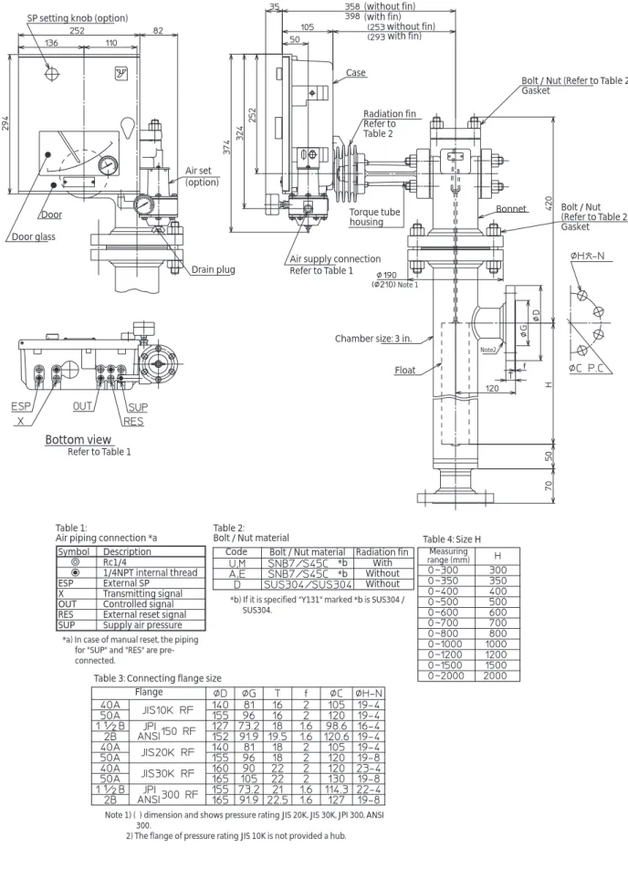
DIMENSIONS
[Unit: mm]
SP setting knob (option)
Air set (option)
Drain plug
Air supply connection Refer to Table 1
Torque tube housing
Note 1
Chamber size: 3 in.
Float
R3/4 Drain plug
Note2
Bonnet Bolt / Nut (Refer to Table 2) Gasket Bolt / Nut (Refer to Table 2) Gasket Radiation fin Refer to Table 2 Case (without fin) (253 without fin) (with fin) with fin) Door Door glass Table 2: Bolt / Nut material Table 1:
Air piping connection *a Symbol Description Rc1/4
1/4NPT internal thread ESP External SP X Transmitting signal OUT Controlled signal RES External reset signal SUP Supply air pressure
Code Bolt / Nut material
With Without Without Radiation fin *b *b Table 4: Size H Measuring range (mm)
Table 3: Connecting flange size Flange
Refer to Table 1 Bottom view
*b) If it is specified "Y131" marked *b is SUS304 / SUS304.
*a) In case of manual reset, the piping for "SUP" and "RES" are pre-connected.
Note 1) ( ) dimension and shows pressure rating JIS 20K, JIS 30K, JPI 300, ANSI 300.
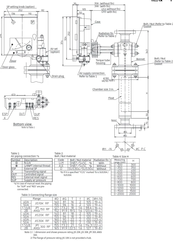
[Unit: mm]
SP setting knob (option)
Air set (option)
Drain plug
Air supply connection Refer to Table 1
Torque tube housing
Note 1
Chamber size: 3 in.
Float
Note2
Bonnet Bolt / Nut (Refer to Table 2) Gasket Bolt / Nut (Refer to Table 2) Gasket Radiation fin Refer to Table 2 Case (without fin) without fin) (with fin) with fin) Door Door glass Table 2: Bolt / Nut material Table 1:
Air piping connection *a Symbol Description Rc1/4
1/4NPT internal thread ESP External SP X Transmitting signal OUT Controlled signal RES External reset signal SUP Supply air pressure
Code Bolt / Nut material
With Without Without Radiation fin *b *b Table 4: Size H Measuring range (mm)
Table 3: Connecting flange size Flange
Refer to Table 1
Bottom view
*b) If it is specified "Y131" marked *b is SUS304 / SUS304.
*a) In case of manual reset, the piping for "SUP" and "RES" are pre-connected.
Note 1) ( ) dimension and shows pressure rating JIS 20K, JIS 30K, JPI 300, ANSI 300.
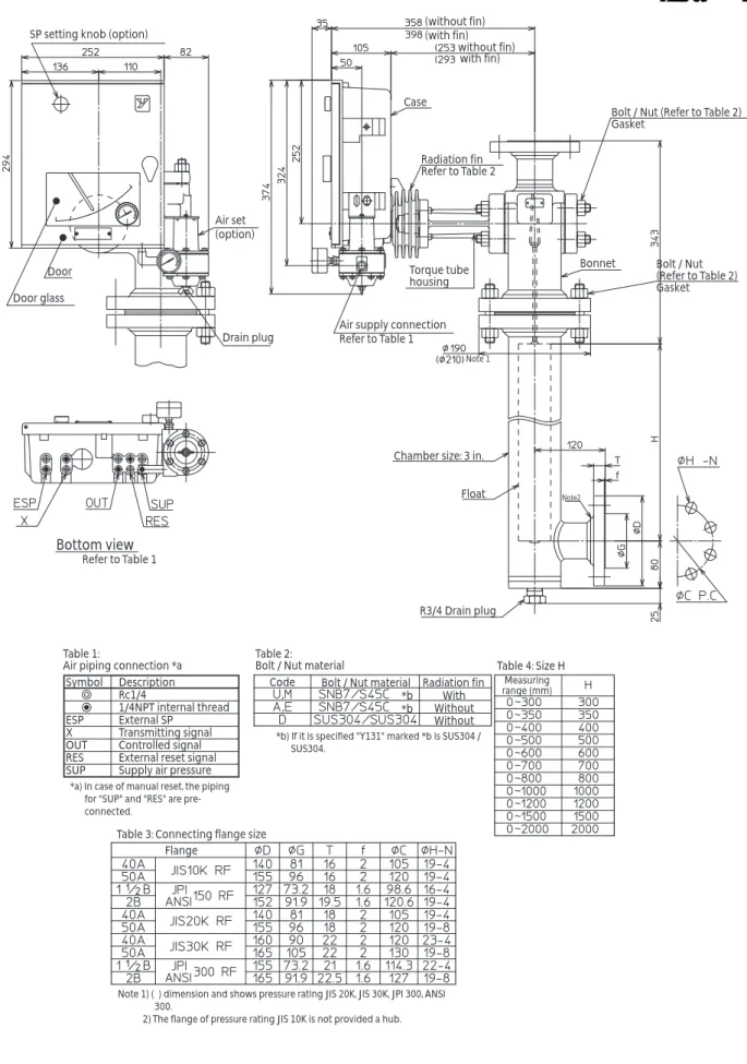
[Unit: mm]
SP setting knob (option)
Air set (option)
Drain plug
Air supply connection Refer to Table 1
Torque tube housing
Note 1
Chamber size: 3 in.
Float
Note2
Bonnet Bolt / Nut (Refer to Table 2) Gasket Bolt / Nut (Refer to Table 2) Gasket Radiation fin Refer to Table 2 Case (without fin) without fin) (with fin) with fin) Door Door glass Table 2: Bolt / Nut material Table 1:
Air piping connection *a Symbol Description Rc1/4
1/4NPT internal thread ESP External SP X Transmitting signal OUT Controlled signal RES External reset signal SUP Supply air pressure
Code Bolt / Nut material
With Without Without Radiation fin *b *b Table 4: Size H Measuring range (mm)
Table 3: Connecting flange size Flange
Refer to Table 1 Bottom view
*b) If it is specified "Y131" marked *b is SUS304 / SUS304.
*a) In case of manual reset, the piping for "SUP" and "RES" are pre-connected.
Note 1) ( ) dimension and shows pressure rating JIS 20K, JIS 30K, JPI 300, ANSI 300.
[Unit: mm]
SP setting knob (option)
Air set (option)
Drain plug
Air supply connection Refer to Table 1
Torque tube housing
Note 1
Chamber size: 3 in.
Float
R3/4 Drain plug
Note2
Bonnet Bolt / Nut (Refer to Table 2) Gasket Bolt / Nut (Refer to Table 2) Gasket Radiation fin Refer to Table 2 Case (without fin) without fin) (with fin) with fin) Door Door glass Table 2: Bolt / Nut material Table 1:
Air piping connection *a Symbol Description Rc1/4
1/4NPT internal thread ESP External SP X Transmitting signal OUT Controlled signal RES External reset signal SUP Supply air pressure
Code Bolt / Nut material With Without Without Radiation fin *b *b Table 4: Size H Measuring range (mm)
Table 3: Connecting flange size Flange
Refer to Table 1
Bottom view
*b) If it is specified "Y131" marked *b is SUS304 / SUS304.
*a) In case of manual reset, the piping for "SUP" and "RES" are pre-connected.
Note 1) ( ) dimension and shows pressure rating JIS 20K, JIS 30K, JPI 300, ANSI 300.
[Unit: mm]
SP setting knob (option)
Air set (option)
Drain plug
Air supply connection Refer to Table 1 Torque tube housing Note 1 Float Bonnet
Bolt / Nut (Refer to Table 2) Gasket Radiation fin Refer to Table 2 Case (without fin) without fin) (with fin) with fin) Door Door glass Table 2: Bolt / Nut material Table 1:
Air piping connection *a Symbol Description Rc1/4
1/4NPT internal thread ESP External SP X Transmitting signal OUT Controlled signal RES External reset signal SUP Supply air pressure
Code Bolt / Nut material
With Without Without Radiation fin *b *b Table 4: Size H Measuring range (mm)
Table 3: Connecting flange size Flange
Refer to Table 1
Bottom view
*b) If it is specified "Y131" marked *b is SUS304 / SUS304.
*a) In case of manual reset, the piping for "SUP" and "RES" are pre-connected.
Note 1) The flange of pressure rating JIS 10K is not provided a hub.
Advanced Automation Company 1-12-2 Kawana, Fujisawa
Kanagawa 251-8522 Japan URL:http://www.azbil.com