PROCESS FIELD BUS
PROFIBUS
Technical Description
September 1999
Technical Description, Order-No. 4.002
September 1999
Published by
PROFIBUS Nutzerorganisation e.V.
Haid-und-Neu-Str. 7
D-76131 Karlsruhe
Phone: ++ 49 721 / 96 58 590
Fax: ++ 49 721 / 96 58 589
e-mail: [email protected]
http://www.profibus.com
Liability Exclusion
We have tested the contents of this document regarding agreement with the hardware and
software described. Nevertheless, deviations can’t be excluded, and we are not guaranteeing
complete agreement. The data in this document is checked periodically, however. Necessary
corrections will be obtained in subsequent versions. We gratefully accept suggestions for
improvement. This manual is not a substitute for the PROFIBUS standard EN 50170. In case of
doubt, EN 50170 takes precedence.
2. PROFIBUS Technology __________________________________________________________________________ 3 2.1 Communication Profiles ... 3 2.2 Physical Profiles ... 3 2.3 Application Profiles... 4 3. Basic Characteristics ____________________________________________________________________________ 4 3.1 Protocol Architecture ... 5 3.2 RS-485 Transmission Technology ... 5
3.3 IEC 1158-2 Transmission Technology ... 7
3.4 Fiber Optic Transmission ... 10
3.5 PROFIBUS Medium Access Protocol... 10
4. DP Communication Profile ______________________________________________________________________ 12 4.1 Basic Functions ... 12
4.1.1 Basic Characteristics ... 13
4.1.2 System Configuration and Types of Devices ... 13
4.1.3 System behavior ... 14
4.1.4 Cyclic Data Transmission between the DPM1 and the Slaves ... 15
4.1.5 Sync and Freeze Mode ... 15
4.1.6 Protection Mechanisms... 15
4.2 Extended DP Functions... 16
4.2.1 Addressing with Slot and Index... 16
4.2.2 Acyclic Data Transmission between the DPM1 and the Slaves ... 16
4.2.3 Acyclic Data Transmission between DPM2 and the Slaves ... 17
5. FMS Communication Profile _____________________________________________________________________ 18 5.1 FMS Services ... 19
5.2 Lower Layer Interface (LLI) ... 19
5.3 Network Management ... 20
6. Application Profiles ____________________________________________________________________________ 20 6.1 Process Automation (PA) ... 20
6.1.1 Communication Aspects ... 21
6.1.2 Application aspects ... 22
6.1.3 PA Function Blocks... 23
6.2 Failsafe Applications ... 24
6.3 Building automation... 24
6.4 Application Profiles for Special Device Types ... 25
7. Device Engineering ____________________________________________________________________________ 25 7.1 GSD Files ... 25
7.2 Ident Number ... 26
7.3 Electronic Device Description (EDD)... 26
7.4 FDT Concept ... 27
8. Implementation Options_________________________________________________________________________ 27 8.1 Implementation of Simple Slaves ... 27
8.2 Implementation of Intelligent Slaves... 28
8.3 Implementation of Complex Masters ... 28
8.4 Implementation of IEC 1158-2 Interfaces ... 28 9. Device Certification ____________________________________________________________________________ 28 10. Further Technical Developments ________________________________________________________________ 30 11. Outlook _____________________________________________________________________________________ 32 12. List of Abbreviations __________________________________________________________________________ 33
Industrial Communication
1. Industrial Communication
Information technology (IT) is increasingly deter-mining growth in automation technology. It has changed hierarchies, structures and flows in the entire office world and now covers all sectors – from the process and manufacturing industries to logis-tics and building automation. The communications capability of devices and continuous, transparent information routes are indispensable components of future-oriented automation concepts. Communi-cation is becoming increasingly direct, horizontally at field level as well as vertically through all hierar-chy levels. Depending on the application and the price, graduated, matching industrial communica-tion systems such as Ethernet, PROFIBUS and AS-Interface offer the ideal preconditions for transpar-ent networking in all areas of the production proc-ess.
At actuator/sensor level the signals of the binary sensors and actuators are transmitted via a sen-sor/actuator bus. Here, a particularly simple, low-cost installation technique, through which data and a 24-volt power supply for the end devices are transmitted using a common medium, is an impor-tant requirement. The data are transmitted purely cyclically. AS-Interface is a suitable bus system for this field of applications.
At field level the distributed peripherals, such as I/O modules, measuring transducers, drive units, valves and operator terminals communicate with the automation systems via an efficient, real-time
communication system. The transmission of the process data is effected cyclically, while alarms, parameters and diagnostic data also have to be transmitted acyclically if necessary. PROFIBUS meets these requirements and offers a transparent solution for manufacturing as well as for process automation.
At cell level, the programmable controllers such as PLC and IPC communicate with each other. The information flow requires large data packets and a large number of powerful communication functions. Smooth integration into company-wide communica-tion systems, such as Intranet and Internet via TCP/IP and Ethernet are important requirements.
The IT revolution in automation technology is opening up new savings potentials in the optimiza-tion of system processes and makes an important contribution towards improved use of resources. Industrial communication systems have assumed a key function in this respect. The following provides a detailed explanation of PROFIBUS as a central link in the flow of information in automation. For a description of AS-Interface, please refer to the relevant literature. The integration of PROFIBUS technology in cross-factory communication net-works on the basis of TCP/IP is explained in detail in the chapter "Further Technical Developments".
PROFIBUS
&H OO OH YH O )L HO G OH YH O (6(6PROFIBUS on Ethernet/TCP-IP
PLC
PLC
6 H QV RU $F WX DWR U OH YH O IEC 1158-2 RS-485/FOManufacturing
Manufacturing
Process
Process
Internet Internet 26 ,,33&& AS-Interface &R PS OH [LW\ &R VWV ([SORVLRQ SURWHFWLRQ
PROFIBUS
2. PROFIBUS Technology
PROFIBUS is a vendor-independent, open field bus standard for a wide range of applications in manu-facturing and process automation. Vendor-independence and openness are ensured by the international standards EN 50170 and EN 50254. PROFIBUS allows communication between devices of different manufacturers without any special interface adjustment. PROFIBUS can be used for both high-speed time critical applications and complex communication tasks. Through its con-tinuing further technical developments, PROFIBUS is still the industrial communication system pre-pared for the future.
PROFIBUS offers functionally graduated communi-cation protocols (Communicommuni-cation Profiles): DP and FMS. Depending on the application, the trans-mission technologies (Physical Profiles) RS-485, IEC 1158-2 or fiber optics are available. In the course of further technical development, the PRO-FIBUS User Organization is currently working on the implementation of universal concepts for vertical integration on the basis of TCP/IP.
Application Profiles define the options of protocol and transmission technology required in the re-spective application area for the individual device types. These profiles also define vendor-independent device behavior.
2.1 Communication Profiles
PROFIBUS Communication Profiles define how users transmit their data serially via the common transmission medium.
DP
DP is the most frequently used communication profile. It is optimized for speed, efficiency and low connection costs and is designed especially for communication between automation systems and distributed peripherals. DP is suitable as a re-placement for conventional, parallel signal trans-mission with 24 volts in manufacturing automation as well as for analog signal transmission with 4 ... 20 mA or Hart in process automation.
FMS
This is the universal communication profile for demanding communication tasks. FMS offers many sophisticated application functions for communi-cation between intelligent devices. However, as a result of the further technical development of PRO-FIBUS and the use of TCP/IP at cell level, FMS will play an increasingly less significant role in the future.
2.2 Physical Profiles
The application area of a field bus system is largely determined by the choice of transmission technol-ogy available. As well as the general demands made on bus systems, such as high
RS-485
IEC 1158-2
Ethernet
Fiber Optics
PA
(Process Automation)Encoder
PROFISafe
(Fail Safe)Physical
Physical
Profiles
Profiles
Communication
Communication
Profiles
Profiles
Application
Application
Profiles
Profiles
PROFIBUS EN 50170
PROFIBUS EN 50170
Extensions
Extensions
TCP/IP
F
u
tu
re
D
e
ve
lo
pme
n
ts
PROFIDrive
(Motion Control)...
...
Basic Characteristics
transmission reliability, large distances and high transmission speed, in process automation addi-tional requirements must also be satisfied, such as operation in hazardous areas and the transmission of data and energy on a common cable. Since it is not yet possible to satisfy all requirements with a single transmission technology, there are currently three transmission methods (Physical Profiles) available for PROFIBUS:
• RS-485 transmission for universal applications in manufacturing automation.
• IEC 1158-2 transmission for use in process automation.
• Optical fibers for improved interference immunity and large network distances.
In the course of further technical developments, it is intended to use commercial Ethernet components with 10 Mbit/s and 100 Mbit/s as physical layer for PROFIBUS.
Couplers or links are available for the transition between the various transmission technologies. While couplers transparently implement the protocol taking account of physical circumstances, links are intrinsically intelligent and thus offer extended options for the configuration of PROFIBUS net-works.
2.3 Application Profiles
PROFIBUS Application Profiles describe the inter-action of the communications protocol with the transmission technology being used. They also define the behavior of the field devices during
communication via PROFIBUS. The most important PROFIBUS Application Profile is currently the PA profile, which defines the parameters and function blocks of process automation devices, such as measuring transducers, valves and positioners. Further profiles for variable-speed drives, HMI and encoders define the vendor-independent communi-cation and behavior of the respective device types.
3. Basic Characteristics
PROFIBUS defines the technical characteristics of a serial field bus system with which distributed digital programmable controllers can be networked, from field level to cell level. PROFIBUS is a multi-master system and thus allows the joint operation of several automation, engineering or visualization systems with their distributed peripherals on one bus. PROFIBUS distinguishes between the follow-ing types of device:
Master devices determine the data communication on the bus. A master can send messages without an external request when it holds the bus access rights (the token). Masters are also called active stations.
Slave devices are peripherals such as I/O devices, valves, drives and measuring transducers. They do not have bus access rights and they can only acknowledge received messages or send mes-sages to the master when requested to do so. Slaves are called passive stations. Since they only require a small portion of the bus protocol, their implementation is particularly economical.
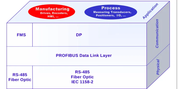
DP
C o m m uni c ati onFMS
RS-485
Fiber Optic
RS-485
Fiber Optic
IEC 1158-2
PROFIBUS Data Link Layer
Appl ication
0DQXIDFWXULQJ
'ULYHV (QFRGHUV +0,3URFHVV
0HDVXULQJ 7UDQVGXFHUV 3RVLWLRQHUV ,2 Ph ys ic al3.1 Protocol Architecture
PROFIBUS is based on recognized international standards. The protocol architecture is oriented to the OSI (Open System Interconnection) reference model in accordance with the international standard ISO 7498. In this model every transmission layer handles precisely defined tasks. Layer 1 (physical layer) defines the physical transmission character-istics. Layer 2 (data link layer) defines the bus access protocol. Layer 7 (application layer) defines the application functions. The architecture of the PROFIBUS protocol is shown in Fig. 4.
DP, the efficient communications protocol, uses layers 1 and 2 as well as the user interface. Layers 3 to 7 are not used. This streamlined architecture ensures fast and efficient data transmission. The Direct Data Link Mapper (DDLM) provides the user interface easy access to layer 2. The application functions available to the user, as well as the sys-tem and device behavior of the various DP device types, are specified in the user interface.
In FMS, the universal communications protocol, particular importance is attached to layers 1, 2 and 7. The application layer (7) consists of the Fieldbus Message Specification (FMS) and the Lower Layer Interface (LLI). FMS defines a large number of powerful communication services for master-master and master-slave communication. The LLI defines
the representation of the FMS services on the data transmission protocol of layer 2.
3.2 RS-485 Transmission Technology
RS 485 transmission is the transmission technology most frequently used by PROFIBUS. The applica-tion area includes all areas in which high transmis-sion speed and simple, inexpensive installation are required. Twisted pair shielded copper cable with one conductor pair is used.
The RS 485 transmission technology is easy to handle. Installation of the twisted pair cable does not require expert knowledge. The bus structure permits addition and removal of stations or step-by-step commissioning of the system without influenc-ing the other stations. Later expansions have no effect on stations which are already in operation. Transmission speeds between 9.6 kbit/sec and 12 Mbit/sec are available. One unique transmission speed is selected for all devices on the bus when the system is commissioned.
Installation Instructions for RS 485
All devices are connected in a bus structure (i.e., line). Up to 32 stations (master or slaves) can be connected in one segment.
Application Profiles IEC Interface IEC 1158-2 User La y e r (3)-(6) Application (7) Data Link (2) Physical (1) Not used
EN 50 170 and PROFIBUS Guidelines PROFIBUS Profiles
Fieldbus Data Link (FDL) Fieldbus Message
Specification (FMS)
RS-485 / Fiber Optic
DP-Grundfunktionen
Fields of Application
(Manufacturing, Process, Building)
DP-Functions
Basic Characteristics
The bus is terminated by an active bus terminator at the beginning and end of each segment (see Fig. 6). To ensure error-free operation, both bus termi-nators must always be powered. The bus terminator can usually be switched in the devices or in the bus terminator connectors.
In the case of more than 32 users, or to enlarge the area of the network, repeaters (line amplifiers) must be used to link up the individual bus segments. The maximum cable length depends on the trans-mission speed, see Table 2. Cable length specifica-tions in Table 2 are based on type-A cable with the following parameters:
•
Impedance:
135 to 165
Ω
•
Capacity:
< 30 pf/m
•
Loop resistance: 110
Ω
/km
•
Wire gauge:
0.64 mm
•
Conductor area > 0.34 mm²
The use of cables of the previously used type B is generally not recommended. In degree of protection IP20, the use of a 9-pin D sub connector is prefer-able for PROFIBUS networks using RS 485 trans-mission technology. The pin assignment of the connector and the wiring are shown in Figure 6. Three alternative connections are possible for RS-485 transmission using degree of protection IP65/67:
- M12 circular connector according to IEC 947-5-2 - HAN-BRID connector according to DESINA recommendations
- Siemens hybrid connector
The HAN-Brid connector system also offers a variant for transmitting data via fiber optic and 24 volt power supply for peripherals via copper cable in a common hybrid cable.
PROFIBUS cables are offered by various well-known manufacturers. A particular feature is the fast-connect system which, thanks to a special cable and special cable stripper, allows fast, reliable and extremely simple wiring.
When connecting the stations, make sure that the data lines are not reversed. Use of shielded data lines is absolutely essential for achieving high
Medium Shielded twisted pair cable.
Number of stations 32 stations in each segment without repeater. With repeaters, this can be extended to 126.
Connectors Preferably 9-pin D-sub connector for IP 20
M12, HAN-BRID or Siemens hybrid connector for IP65/67
Table 1: Basic characteristics of RS-485 transmission technology
1
4 3
2
5
M12 Connector for RS-485 in IP65/67 Pin assignment: 1: VP, 2: RxD/TxD-N
3: DGND; 4: RxD/TxD-P; 5: Shield
Han-Brid Connector in Cu-Fo Version
for transmission of data via the fibers and 24 volt power supply for the peripherials in a single connector. This connector is also available in Cu/Cu version.
B-Line (red) A-Line (green)
Shielding (PE) PE M24 P24 1 2 3 4 5 6
Siemens-Hybrid-Connector for transmission of both 24 volt power supply and PROFIBUS data via copper wires for devices with IP 65 protection.
Fig. 5: Options for PROFIBUS connectors in protection class IP 65/67.
system immunity against high electromagnetic emissions. The shield should be connected to protective ground on both sides and with good conductivity using large-area shield clamps. In addition, it is recommended that data lines be kept separate from all high-voltage cables. The use of stub lines must be avoided for data transmission speeds of ≥ 1.5 Mbit/s. Commercially available plug connectors permit the incoming data cable and the outgoing data cable to be connected directly in the connector. This means that stub lines do not have to be used, and the bus connector can be con-nected and disconcon-nected at the bus at all times without interrupting data communication.
Whenever problems occur in PROFIBUS networks, in 90 % of all cases they can be attributed to incor-rect wiring and installation. These problems can often be solved using bus testers, which can detect many typical wiring faults even before commission-ing. For the addresses of suppliers of the many different connectors, cables, repeaters and bust-esters, please refer to the PROFIBUS Product Guide.
3.3 IEC 1158-2 Transmission Technology
Synchronous transmission in accordance with IEC 1158-2 with a defined baud rate of 31.25 kbit/s is used in process automation. It satisfies important requirements in the chemical and petrochemical industries: intrinsic safety and powering over the bus using two-wire technology. Thus PROFIBUScan be used in hazardous areas.
The options and limits of PROFIBUS with IEC 1158-2 transmission technology for use in poten-tially explosive areas are defined by the FISCO model (Fieldbus Intrinsically Safe Concept). The FISCO model was developed in Germany by the Physikalisch Technische Bundesanstalt (PTB) (Federal Physical Technical Institute) and is today internationally recognized as the basic model for fieldbuses in hazardous areas. Transmission in accordance with IEC 1158-2 and FISCO model is based on the following principles:
• Each segment has only one source of power, the power supply unit.
• No power is fed to the bus when a station is sending.
• Every field device consumes a constant basic current at steady-state.
• The field devices function as a passive current sink.
• The passive line termination is performed at both ends of the main bus line.
• Linear, tree and star topologies are allowed. In steady state, each station consumes a basic current of at least 10 mA. With bus powering, this current serves to supply energy to the field device. Communication signals are generated by the sending device by modulation from +/- 9 mA to the basic current.
Baud rate (kbit/s) 9.6 19.2 93.75 187.5 500 1500 12000
Range/Segment 1200 m 1200 m 1200 m 1000 m 400 m 200 m 100 m
Table 2: Range based on transmission speed for type-A cable
Station 1 Station 2 Shielding Protective ground Protective ground RxD/TxD-P (3) DGND (5) VP (6) RxD/TxD-N (8) (3) RxD/TxD-P (5) DGND (6) VP (8) RxD/TxD-N 390 Ω Data line Data line DGND (5) VP (6) 220 Ω 390 Ω RxD/TxD-P (3) RxD/TxD-N (8)
Cabling Bus Termination
Basic Characteristics
To operate a PROFIBUS network in hazardous areas, it is necessary for all components used in the hazardous areas to be approved and certified in accordance with the FISCO model and IEC 1158-2 by authorized approval agencies such as PTB, BVS (Germany) UL, FM (US). If all of the components used have been certified as required, and if the following rules for selecting the supply unit, line length and bus terminators are complied with, then no further system approval is required for commis-sioning of the PROFIBUS network.
Installation Instructions for IEC-1158
The control station usually contains the process control system as well as operating and engineering devices which communicate via PROFIBUS and RS-485 transmission. In the field, a segment cou-pler or a link forms the transition from the RS-485 segment to the IEC 1158-2 segment. At the same
time, the coupler or link is the supply unit for the bus powered field devices.
Segment couplers are signal converters that adapt the RS-485 signals to the IEC 1158-2 signal level. From the point of view of the bus protocol, they are transparent. If segment couplers are used, the baud rate in the RS-485 segment is restricted to a maximum of 93.75 kbit/s.
Links, on the other hand, have their own intrinsic intelligence. They represent all field devices con-nected in the IEC 1158-2 segment as a single slave in the RS-485 segment. There is no limit to the baud rate in the RS-485 segment when using links. This means that it is also possible to implement fast networks, i.e. for control functions, including field devices with an IEC 1158-2 connection.
Data transmission Digital, bit-synchronous, Manchester coding
Transmission speed 31,25 kbit/s, Voltage Mode
Data security Preamble, error-proof start and end delimiter
Cable Two wire shielded twisted pair cable
Remote powering Optional, via data lines
Explosion protection classes Intrinsically safe (EEx ia/ib) and encapsulation (EEx d/m/p/q)
Topology Line and tree topologies, or a combination
Number of stations Up to 32 stations per line segment, maximum total of 126
Repeater Can be expanded with up to 4 repeaters
Table 3: Characteristic features of IEC 1158-2 transmission technology
PROFIBUS
IEC 1158-2 mit 31.25 kbit/s 100Ω
µF 1 Shielded twisted pair cable
≥ 10 mA ≥ 10 mA ≥ 10 mA ≥ 10 mA ≥ 10 mA 24 V Stub line Segment coupler or Link PROFIBUS
ε
x
+
I < 120 mA Control System RS 485 Bus terminatorTree or line structures are possible network topolo-gies for PROFIBUS with IEC 1158-2 transmission, as well as any combinations of the two, see Fig. 7. In a line structure, stations are connected to the main cable using T-connectors. A tree structure can be compared to the classic field installation tech-nique. The multi-core master cable is replaced by the two-wire bus cable. The field distributor contin-ues to be used for connection of the field devices and to house the bus terminating resistor. When a tree structure is used, all field devices connected to the fieldbus segment are wired in parallel in the field distributor.
In all cases, the maximum permissible stub line lengths must be taken into consideration when calculating the total line length. A stub line may not
be longer than 30m in intrinsically safe applications. A shielded two-wire cable is used as the transmis-sion medium, see Fig.7. The main bus cable is fitted at both ends with a passive line terminator, consisting of an RC element connected in series with R = 100 Ω and C = 1 µF. In the segment cou-pler or link the bus terminator is already perma-nently integrated. A reversed-polarity connection of a field device using IEC 1158-2 technology has no effect on the correct functioning of the bus, since these field devices are usually fitted with automatic polarity detection.
The number of stations that can be connected to one segment is limited to a maximum of 32. How-ever, this number may be further restricted by the selected type of protection and bus powering. In intrinsically safe networks, the maximum supply voltage as well as the maximum supply current are defined within strict limits. Even when intrinsic safety is not required, the power of the power supply unit is limited.
As a rule of thumb for determining the maximum line length, it is sufficient to calculate the power requirements of the field devices to be connected, to select a supply unit from Table 5 and to read off the line length for the selected type of cable from Table 6. The required current ( =Σ power require-ments) is obtained from the sum of the basic cur-rents of the devices, of the field devices connected in the selected segment, as well as a reserve of 9 mA per segment for the operating current of the FDE (Fault Disconnection Equipment). The FDE
Cable design Shielded twisted
pair cable
Conductor area (nominal) 0.8 mm² (AWG 18)
Loop resistance: 44 Ω/km
Impedance at 31.25 kHz 100 Ω± 20 % Wave attenuation at 39 kHz 3 dB/km
Capacitive asymmetry 2 nF/km
Table 4: Specification of the reference cable for IEC 1158-2 transmission
Type Application Supply voltage Maximum
supply current
Maximum power
Typical*) no. of stations
I EEx ia/ib IIC 13.5 V 110mA 1.8 W 9
II EEx ib IIC 13.5 V 110mA 1.8 W 9
III EEx ib IIB 13.5 V 250 mA 4.2 W 22
IV Not intrinsically safe 24 V 500 mA 12 W 32
*) this is based on power consumption of 10 mA per device. If a device consumes more than 10 mA, the number of devices that can be connected must be reduced accordingly.
Table 5: Standard power supply units (operating values) for PROFIBUS with IEC 1158-2 transmission
Supply unit Type I Type II Type III Type IV Type IV Type IV
Supply voltage V 13.5 13.5 13.5 24 24 24
Σ Power requirements mA ≤ 110 ≤ 110 ≤ 250 ≤ 110 ≤ 250 ≤ 500
Σ Line length for q=0.8 mm²(reference)
m ≤ 900 ≤ 900 ≤ 400 ≤ 1900 ≤ 1300 ≤ 650
Σ Line length for q=1.5 mm²
m ≤ 1000 ≤ 1500 ≤ 500 ≤ 1900 ≤ 1900 ≤ 1900
Basic Characteristics
prevents faulty devices from blocking the bus permanently.
Joint operation of bus powered and externally powered devices is permissible. It must be noted that even externally supplied devices consume a basic current via the bus connection, and this must also be taken into account when calculating the maximum available supply current.
3.4 Fiber Optic Transmission
Fiber optic conductors may be used in PROFIBUS for applications in environments with very high electromagnetic interference, for electrical isolation or to increase the maximum network distance for high transmission speeds. Various types of fibers are available, with different characteristics with respect to distance, price and application. For a short overview please refer to Table 7.
PROFIBUS segments using fiber-optic technology are designed using either a star or a ring structure. The PROFIBUS fiber optic components from some manufacturers also allow the creation of redundant fiber optic links with automatic switchover to the alternative physical transmission route in the event of a fault. Many manufacturers also offer couplers between RS-485 transmission links and optical
fibers. This provides a method of switching at any time between RS 485 transmission and fiber optic transmission within one system. See PROFIBUS guideline 2.022 for the specification of the PRO-FIBUS fiber optic transmission technique. For an overview of the fiber-optic components available for PROFIBUS, please refer to the current PROFIBUS Product Guide.
3.5 PROFIBUS Medium Access Protocol
The PROFIBUS Communication Profiles use a uniform medium access protocol. This protocol is implemented by layer 2 of the OSI reference model. This also includes data security and the handling of the transmission protocols and telegrams. In PRO-FIBUS, layer 2 is called Fieldbus Data Link (FDL). The Medium Access Control (MAC) specifies the procedure when a station is permitted to transmit data. The MAC must ensure that only one station has the right to transmit data at a time. The PRO-FIBUS protocol has been designed to meet two primary requirements for the Medium Access Con-trol:Type of fiber Properties
Multimode glass fiber Medium distance range, 2 – 3 km range Monomode glass fiber Long distance range, > 15 km range Synthetic fiber Short distance range, > 80 km range PCS/HCS fiber Short distance range, > 500 m range
Table 7: Properties of optical fibers
PROFIBUS
Passive stations (slave devices) are polled Active stations, master devices
PLC
PLC
PC
Fig. 8: shows a PROFIBUS configuration with three active stations (masters) and seven passive stations (slaves). The three masters form a logical token ring.
• During communication between complex auto-mation systems (masters), it must be ensured that each of these stations gets sufficient time to perform its communication tasks within a precisely defined time interval.
• On the other hand, for communication between a complex programmable controller and its as-signed simple peripherals (slaves), cyclic, real-time data transmission needs to be imple-mented as fast and as simply as possible. Therefore, the PROFIBUS medium access protocol (see Figure 8) includes the token passing proce-dure, which is used by complex bus stations (mas-ters) to communicate with each other, and the master-slave procedure used by complex bus stations to communicate with the simple peripherals (slaves).
The token passing procedure ensures that the bus access right (the token) is assigned to each master within a precisely defined timeframe. The token message, a special telegram for passing the token from one master to the next master must be passed around the logical token ring once to all masters within a (configurable) maximum token rotation time. In PROFIBUS the token passing procedure is only used for communication between complex stations (masters).
The master-slave procedure permits the master (the active station) which currently owns the token to access the assigned slaves (the passive sta-tions). This enables the master to send messages to, or retrieve them from the slaves. This method of access allows implementation of the following system configurations:
• Pure master-slave system.
• Pure master-master system (token passing)
• A combination of the two
A token ring means the organizational lining up of active stations which form a logical ring through their bus addresses. In this ring, the token, the bus access right, is passed on from one master to the next master in a predefined sequence (increasing
addresses). When an active station receives the token telegram, it can perform the master role for a certain period of time and communicate with all slave stations in a master-slave communication relationship and all master stations in a master-master communication relationship.
The task of the bus access controller (MAC) of the active station is to detect this logical assignment in the startup phase of the bus system and to estab-lish the token ring. During operation, defective or switched-off (active) stations must be removed from the ring and new active stations can be added to the ring. In addition, the bus access control ensures that the token is passed from one master to the next in order of increasing addresses.
The actual token hold time of a master depends on the configured token rotation time. In addition, the detection of defects on the transmission medium and on the line receiver, as well as the detection of errors in station addressing (e.g., multiple ad-dresses assigned) or in token passing (e.g., multi-ple tokens or token loss) are characteristic features of the PROFIBUS medium access control.
Another important task of layer 2 is data security. PROFIBUS layer 2 frame formats ensure high data integrity. All telegrams have a Hamming Distance of HD=4. This is achieved through compliance with the international standard IEC 870-5-1, through special telegram start and end delimiters, slip-free synchronization, a parity bit and a check byte. PROFIBUS layer 2 operates in a connectionless mode. In addition to logical peer-to-peer data transmission, it provides multi-peer communication (broadcast and multicast).
Broadcast communication means that an active station sends an unacknowledged message to all other stations (master and slaves).
Multicast communication means that an active station sends an unacknowledged message to a predetermined group of stations (master and slaves).
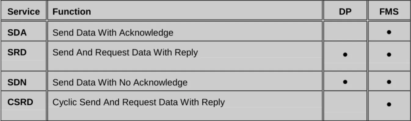
Service Function DP FMS
SDA Send Data With Acknowledge
•
SRD Send And Request Data With Reply
•
•
SDN Send Data With No Acknowledge
•
•
CSRD Cyclic Send And Request Data With Reply
•
DP Communication Profile
The PROFIBUS Communication Profiles each use a specific subset of layer 2 services, see Table 8. The services are called up by the higher-order layers via the service access points (SAPs). In FMS these service access points are used to address the logical communication relationships.
In DP a precisely defined function is assigned to each service access point. Several service access points can be used simultaneously for all active and passive stations. A distinction is made between source (SSAP) and destination service access points (DSAP).
4. DP Communication Profile
The DP Communication Profile is designed for efficient data exchange at the field level. The cen-tral automation devices, such as PLC/PC or proc-ess control systems, communicate through a fast serial connection with distributed field devices such as I/O, drives and valves, as well as measuringtransducers. Data exchange with the distributed devices is mainly cyclic. The communication func-tions required for this are defined by the basic DP functions in accordance with EN 50 170. In addition to these basic functions, DP also offers extended acyclic communication services for the parameter-ization, operation, monitoring and alarm handling of intelligent field devices. They are defined in the PROFIBUS Guideline No. 2.042 and are explained in Chapter 4.2.
4.1 Basic Functions
The central controller (master) cyclically reads the input information from the slaves and cyclically writes the output information to the slaves. The bus cycle time should be shorter than the program cycle time of the central automation system, which for many applications is approximately 10 msec. In addition to cyclic user data transmission, DP pro-vides powerful functions for diagnostics and com-missioning. Data communication is monitored by Bus access:
• Token passing procedure between masters and master-slave procedure between master and slaves
• Mono-master or multi-master systems possible
• Master and slave devices, max. 126 stations on one bus Communication:
• Peer-to-peer (user data communication) or multicast (control commands)
• Cyclic master-slave user data communication Operating states:
• Operate: Cyclic transmission of input and output data
• Clear: Inputs are read, outputs remain in secure state
• Stop: Diagnostics and parameterization, no user data transmission Synchronization:
• Control commands allow the synchronization of inputs and outputs
• Sync mode: Outputs are synchronized
• Freeze mode: Inputs are synchronized Functions:
• Cyclic user data transfer between DP master and slave(s)
• Dynamic activation or deactivation of individual slaves
• Checking the configuration of the slaves
• Powerful diagnostic functions, 3 hierarchical levels of diagnostic messages
• Synchronization of inputs and/or outputs
• Address assignment for slaves optionally possible via the bus
• maximum of 244 bytes input and output data possible for each slave Protective functions:
• All messages are transmitted at a hamming distance of HD=4
• Watchdog control of DP slave detects failure of the assigned master
• Access protection for inputs/outputs of slaves
• Monitoring of user data communication with adjustable monitoring timer in the master Device types:
• DP master Class 2 (DPM2), e.g. engineering or diagnostics tool
• DP master Class 1 (DPM1), e.g. central programmable controllers such as PLC, PC ....
• DP slave e.g. devices with binary or analog inputs/outputs, drives, valves
monitoring functions on both the master and slave side. Table 9 provides a summary of the basic DP functions.
4.1.1 Basic Characteristics
High data throughput alone is not the sole criteria for successful use of a bus system. Simple han-dling, good diagnostic capabilities and interference-proof transmission technology are also important to the user. DP represents the optimum combination of these characteristics.
Speed:
DP requires only about 1 msec at 12 Mbit/sec for the transmission of 512 bits of input data and 512 bits of output data distributed over 32 stations. Figure 9 shows the typical DP transmission time, depending on number of stations and transmission speed. Transmitting the input and output data in a single message cycle with DP, results in a signifi-cant increase in speed compared to FMS. In DP, user data is transmitted with the SRD service of layer 2.
Diagnostic functions:
The extensive diagnostic functions of DP enable fast location of faults. The diagnostic messages are transmitted over the bus and collected at the mas-ter. These messages are divided into three levels:
• Station-related diagnostics
These messages concern the general opera-tional status of a station (i.e. overtemperature or low voltage).
• Module-related diagnostics
These messages indicate that within a certain I/O range (e.g. 8 bit output module) of a station, diagnostics are pending.
• Channel-related diagnostics
In this case, the cause of the fault is specified in relation to an individual input/output bit (chan-nel), e.g. short circuit at output 7.
4.1.2 System Configuration and Types of
Devices
DP permits mono-master or multi-master sys-tems. This provides a high degree of flexibility during system configuration. A maximum of 126 devices (master or slaves) can be connected to one bus. The system configuration specifications define the number of stations, assignment of station ad-dresses to the I/O adad-dresses, data consistency of the I/O data, format of the diagnostic messages and the bus parameters used. Each DP system consists of different types of devices. A distinction is made between three types of devices:
DP Master Class 1 (DPM1)
This is a central controller which cyclically ex-changes information with the distributed stations (slaves) in a defined message cycle. Typical de-vices are, for example, programmable logic con-trollers (PLC) or PC.
DP Master Class 2 (DPM2)
Devices of this type are engineering, configuration
Bus Cycle Time
[ms]
Slaves
12 MBit/s
1.5 MBit/s
500 kBit/s
18
14
10
6
2
10
20
30
2
DP Communication Profile
or operating devices. They are used for commis-sioning and for maintenance and diagnostics, in order to configure the connected devices, evaluate measured values and parameters, and request the device status.
Slave
A slave is a peripheral device (I/O devices, drives, HMI, valves, measuring transducers) which collects input information and sends output information to the peripherals. There are also devices which supply only input or only output information.
The amount of input and output information de-pends on the device type. A maximum of 246 bytes of input data and 246 bytes of output data is per-mitted.
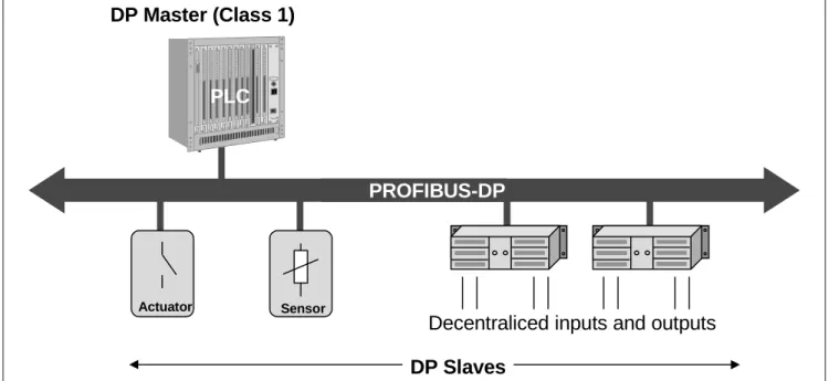
In mono-master systems only one master is active on the bus during operation of the bus system. Figure 10 shows the system configuration of a mono-master system. The programmable controller is the central control component. The slaves are decentrally linked to the PLC via the transmission medium. Mono-master systems attain the shortest bus cycle time.
In multi-master configurations several masters are connected to one bus. These masters represent either independent subsystems, each consisting of one DPM1 master and its assigned slaves, or additional configuration and diagnostic devices. The input and output images of the slaves can be read by all DP masters. However, only one DP master (i.e., the DPM1 assigned during configuration) may write-access the outputs.
4.1.3 System behavior
The DP specification includes a detailed description of system behavior to ensure device interchange-ability. System behavior is determined primarily by the operating status of the DPM1.
DPM1 can be controlled either locally or via the bus by the configuration device. There are three main states:
• Stop
In this state, no data transmission occurs be-tween the DPM1 and the slaves.
• Clear
In this state, the DPM1 reads the input informa-tion of the slaves and holds the outputs in fail-safe status.
• Operate
In this state, the DPM1 is in the data transfer phase. In cyclic data communication, inputs of the slaves are read, and output information is written to the slaves.
The DPM1 cyclically sends its status to all slaves assigned to it using a multicast command at a configurable time interval.
The system reaction to an error during the data transfer phase of the DPM1 (such as failure of a slave) is determined by the "auto-clear" configura-tion parameter.
If this parameter is set to true, the DPM1 switches the outputs of all assigned slaves to fail-safe state as soon as a slave is no longer ready for user data
DP Master (Class 1)
Decentraliced inputs and outputs
PROFIBUS-DP
DP Slaves
PLC
Actuator Sensor
transmission. The DPM1 then changes to the Clear state.
If this parameter is false, the DPM1 remains in operate state even when a fault occurs, and the user can specify the system reaction.
4.1.4 Cyclic Data Transmission between the
DPM1 and the Slaves
Data transmission between the DPM1 and the slaves assigned to it is executed automatically by the DPM1 in a defined, recurring order. When configuring the bus system, the user defines the assignment of a slave to the DPM1. He also defines which slaves are to be included in, or excluded from, the cyclic user data communication.
Data transmission between the DPM1 and the slaves is divided into three phases: parameteriza-tion, configuration and data transfer. Before a DP slave enters the data transfer phase, in the param-eterization and configuration phase it is checked, whether the planned configuration matches the actual device configuration. In the course of this check, the device type, format and length informa-tion as well as the number of inputs and outputs must agree. These tests provide the user reliable protection against parameterization errors. In addi-tion to the user data transfer, which is executed automatically by the DPM1, new parameterization data can be sent to the slaves at the request of the user.
4.1.5 Sync and Freeze Mode
In addition to station-related user data transfer, which is executed automatically by the DPM1, the master can send control commands to a single
slave, a group of slaves or all slaves simultane-ously. These control commands are transmitted as multicast commands. They permit use of sync and freeze modes for event-controlled synchronization of the slaves.
The slaves begin sync mode when they receive a sync command from their assigned master.
The outputs of all addressed slaves are then frozen in their current state. During subsequent user data transmissions, the output data are stored at the slaves, but the output states remain unchanged. The stored output data are not sent to the outputs until the next sync command is received. Sync mode is concluded with the unsync command. Similarly, a freeze control command causes the addressed slaves to assume freeze mode. In this operating mode, the states of the inputs are frozen at the current value. Input data are not updated again until the master sends the next freeze com-mand. Freeze mode is concluded with the unfreeze command.
4.1.6 Protection Mechanisms
Security and reliability make it necessary to provide DP with effective protection functions against pa-rameterization errors or failure of the transmission equipment. To achieve this, monitoring mecha-nisms are implemented in the DP master and in the slaves in the form of time monitoring. The monitor-ing interval is defined durmonitor-ing configuration.
Request frame
DP Slave
Im
m
edia
te re
ply
DP Ma
st
e
r
Response frame
Final info
Output data
Head info
Head info
Input data
Final info
DP Communication Profile
At the DP master
The DPM1 monitors data transmission of the slaves with the Data_Control_Timer. A separate control timer is used for each slave. The time monitoring is tripped when correct data transmission does not occur within the monitoring interval. The user is informed when this happens. If the automatic error reaction (Auto_Clear = True) has been enabled, the DPM1 exits its OPERATE state, switches the outputs of all assigned slaves to fail-safe status and changes to the CLEAR status.
At the slave
The slave uses the watchdog control to detect failures of the master or the transmission line. If no data communication with the master occurs within the watchdog control interval, the slave automati-cally switches its outputs to the fail-safe status. In addition, access protection is required for the inputs and outputs of the slaves operating in multi-master systems. This ensures that only the author-ized master has direct access. For all other mas-ters, the slaves offer an image of their inputs and outputs which can be read from any master, even without access rights.
4.2 Extended DP Functions
The extended DP functions make it possible to transmit acyclic read and write functions as well as alarms between master and slaves parallel and independent of cyclic user data communication. This allows the user to use for example an engi-neering tool (DPM2), to optimize the device pa-rameters of the connected field devices (slaves) or read out the device status without disturbing system operation.
With these extended functions, DP meets the requirements of even complex devices which often have to be parameterized during operation. Nowa-days, the extended DP functions are mainly used for the online operation of the PA field devices by means of engineering tools. Transmission of the acyclic required data is performed with a lower priority parallel to the high-speed cyclic user data transfer. The master requires some additional time to carry out the acyclic communication services. This must be taken into account in the parameter-ization of the overall system. To achieve this, the parameterization tool usually increases the token circulation time somewhat in order to give the master a chance to carry out not only cyclic data transmission, but also acyclic communication tasks. These extended functions are optional. They are compatible with basic DP functions. Existing de-vices which do not want or need to use the new functions can continue to be used since the ex-tended functions are only supplements to already existing basic functions. The DP extensions are specified in the technical PROFIBUS guideline No. 2.082.
4.2.1 Addressing with Slot and Index
To address the data, PROFIBUS assumes that the slaves are built up as physical building blocks, or can be structured internally in logical function units, so-called modules. This model is also used in the basic DP functions for cyclic data transmission where each module has a constant number of input and/or output bytes which are transmitted in a fixed position in the user data telegram. The addressing procedure is based on identifiers which characterize the type of a module as input, output or a combina-tion of both. All identifiers together give the configu-ration of a slave, which is also checked by the DPM1 when the system starts up.
The new acyclic services are also based on this model. All data blocks enabled for read or write accesses are also considered as belonging to the modules. These blocks can be addressed by slot number and index. The slot number addresses the module, and the index addresses data blocks belonging to a module. Each data block can have a size of up to 244 bytes, see Fig. 12. With modular devices, the slot number is assigned to the mod-ules. Beginning with 1, the modules are numbered consecutively in increasing order. Slot number 0 is provided for the device itself. Compact devices are treated as one unit of virtual modules. Addressing with slot number and index is also used here. Using the length specification in the read or write request, it is also possible to read or write parts of a data block. If access to the data block was suc-cessful, the slave responds with a positive read or write response. If not successful, the slave gives a negative response in which the problem is classi-fied.
4.2.2 Acyclic Data Transmission between
the DPM1 and the Slaves
The following functions are available for acyclic data communication between the central automa-tion system (DPM1) and the slaves:
MSAC1_Read:
The master reads a data block from the slave MSAC1_Write:
The master writes a data block to the slave MSAC1_Alarm:
Transmission of an alarm from the slave to the master. The receipt of an alarm is explicitly ac-knowledged by the master. Only after the alarm acknowledgement has been received, the slave is able to send a new alarm message. This means that alarms can never be overwritten.
MSAC1_Alarm_Acknowledge:
The master acknowledges the receipt of an alarm message to the assigned slave
MSAC1_Status:
Transmission of a status message from the slave to the master. The receipt of the status message is not acknowledged. Status messages can therefore be overwritten.
Data is transferred connection-oriented via an MSAC1 connection. This connection is established by the DPM1. It is very closely linked to the con-nection for cyclic data communication between the DPM1 and the slaves and can only be used by the master that has also parameterized and configured the slave in question.
4.2.3 Acyclic Data Transmission between
DPM2 and the Slaves
The following functions are available for acyclic data communication between the engineering and operator tools (DPM2) and the slaves:
MSAC2_Initiate and MSAC2_Abort
Establishment and termination of a connection for acyclic data communication between the DPM2 and the slave.
MSAC2_Read:
The master reads a data block from the slave
MSAC2_Write:
The master writes a data block to the slave MSAC2_Data_Transport:
With this service, the master can write data acycli-cally to the slave and if required also read data from the slave in the same service cycle. The meaning of the data is application-specific and defined in pro-files.
The communication is performed connection-oriented. The connection is called MSAC_C2. The connection is established before the beginning of acyclic data communication by the DPM2 with the MSAC2_Initiate service. After this, the connection is available for the MSAC2_Read, MSAC2_Write and MSAC2_Data_Transport services. When a connec-tion is no longer needed, it is disconnected by the master with the MSAC2_Abort service. In general it is possible for a slave to maintain several active MSAC2 connections at the same time. The number of connections that can be kept active at the same time is limited by the resources available in the slave and varies depending on the device type. Acyclic data transmission is effected in a predefined sequence, which will be described in the following with the help of the MSAC2_Read service.
Basic device unit Index 0-255 In de x Modul 1 Index 0-255 8 Digital OUT Modul 2 Index 0-255 16 Digital OUT Modul 3 Index 0-255 8 Digital IN Modul 4 Index 0-255 1 Analog IN 0 1 2 3 4 Representation of data during data transmission 1 byte output (module 1) 2 byte output (module 3) 1 byte input (module 3) 4 byte output (module 4) Request: Response:
...
...
...
Slot_Number in ascending order from left to rightFMS Communication Profile
First the master sends an MSAC2_Read request to the slave; in this request the required data are addressed using the slot number and index. After this request has been received, the slave has the opportunity to make the required data available. The master now sends regular poll telegrams to collect the requested data from the slave. The slave answers the poll telegrams of the master with a brief acknowledgement without data until it has processed the data. The next poll request by the master is then answered with an MSAC2_Read response, with which the read data are transmitted to the master. Data transmission is time-monitored. The monitoring interval is specified with the DDLM_Initiate service when the connection is established. If the connection monitor detects a fault, the connection is automatically disconnected on both the master and the slave side. The connec-tion can then be established again or used by another partner. Service access points 40 to 48 on the slave and service point 50 on the DPM2 are reserved for the MSAC_C2 connection.
5. FMS Communication Profile
The FMS Communication Profile is designed for communication at cell level. At this level, program-mable controllers (PLCs and PCs) communicate primarily with each other. In this application area a high degree of functionality is more important than fast system reaction times.The FMS application layer (7) consists of the fol-lowing parts:
• The Fieldbus Message Specification (FMS) and
• the Lower Layer Interface (LLI)
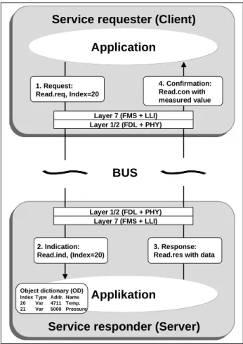
The PROFIBUS-FMS communication model per-mits distributed application processes to be unified into a common process by using communication relationships. That portion of an application process in a field device which can be reached via commu-nication is called a virtual field device (VFD). Figure 13 shows the relationship between the real field device and the virtual field device. In this example, only certain variables (i.e., number of units, rate of failure and downtime) are part of the virtual field device and can be read or written via the two com-munication relationships. The variables Required Value and Recipe are not available with FMS. All communication objects of an FMS device are entered in the object dictionary (OD). The object dictionary contains description, structure and data type, as well as the relationship between the inter-nal device addresses of the communication objects and their designation on the bus (index/name). Static communication objects are entered in the static object dictionary. They are configured once and cannot be modified during operation. FMS recognizes five types of communication objects:
• Simple Variable
• Array (series of simple variables of the same type)
Field device 1
VFD
The VFD is the part of the real field device that is visible for communication
Field device 2
VFD
Real field device
Setpoint
Limit value
Object dictionary (OD)
Data type index
Index Objekt-Code Meaning 1 Data type Integer8 2 Data type Integer16 ...
6 Data type Floating Point Static objec dictionary
Index Objekt- Datatype Internal Symbol
Code address
20 VAR 1 4711 Quantity
21 VAR 6 5000H Failure rate
22 VAR 2 100H Downtime
Virtual field device (VFD)
Recipe
Logical
connectiion
Logical
connection
Quantity Failure rate Downtime
• Record (series of simple variables of different types) • Domain
• Event (event message)
Dynamic communication objects are entered in the dynamic section of the object dictionary. These can be modified during operation.
Logical addressing is the preferred method of addressing for the objects. Accessing is performed with a short address (the index) which is a number of type Unsigned16. Each object has a unique index. An additional option is to address the objects by name.
Communication objects can also be protected from unauthorized access through access protection, or the permitted services for accessing an object (e.g. read only) can be restricted.
5.1 FMS Services
FMS services are a subset of the MMS services (MMS = Manufacturing Message Specification, ISO 9506) which have been optimized for field bus applications and which have been expanded by functions for communication object administration and network management. Figure 14 provides an overview of the available PROFIBUS FMS services. Confirmed services can only be used for connec-tion-oriented communication relationships. The execution of a service is shown in Fig. 15.
Unconfirmed services can also be used on con-nectionless communication relationships (broadcast and multicast). They can be transmitted with high or low priority.
FMS services are divided into the following groups:
• Context Management services are for estab-lishing and terminating logical connections.
• Variable Access services are used to access variables, records, arrays or variable lists.
• Domain Management services are used to transmit large memory areas. The data must be divided into segments by the user.
• Program Invocation Management services are used for program control.
• Event Management services are used to transmit alarm messages. These messages can also be sent as broadcast or multicast transmis-sions.
• VFD Support services are used for identification and status polling. They can also be sent spon-taneously at the request of a device as multicast or broadcast transmissions.
• OD Management services are used for read and write access to the object dictionary.
5.2 Lower Layer Interface (LLI)
The mapping of layer 7 to layer 2 is handled by LLI. Tasks include flow control and connection monitor-ing. The user communicates with the other proc-esses via logical channels called communication relationships. The LLI provides various types of communication relationships for execution of the FMS and management services. The communica-tion relacommunica-tionships have different conneccommunica-tion capa-bilities (i.e., monitoring, transmission and demands on the communication partners).
Connection-oriented communication relation-ships represent a logical peer-to-peer connection between two application processes. The connection must first be established with an Initiate service before it can be used for data transmission. After being successfully established, the connection is protected against unauthorized access and is available for data transmission. When an estab-lished connection is no longer needed, it can be disconnected with the Abort service. The LLI per-mits time-controlled connection monitoring for connection-oriented communication relationships.
Variable Access Read ReadWithType Write WriteWithType PhysicalRead PhysicalWrite InformationReport InformationReportWithType DefineVariableList DeleteVariableList Event Management EventNotification EventNotificationWithType AcknowledgeEventNotification AlterEventConditionMonitoring Only the underlined services must be supported by all
PROFIBUS devices. Selection of additional services
is defined by profiles.
Context Management
Initiate Abort Reject
Program Invocation Management
CreateProgramInvocation DeleteProgramInvocation
Start, Stop, Resume, Reset, Kill
OD-Management GetOD InitiatePutOD PutOD TerminatePutOD VFD Support Status UnsolicitedStatus Identify Domain Management InitiateDownloadSequence DownloadSegment TerminateDownloadSequence InitiateUploadSequence UploadSegment TerminateUploadSequence RequestDomainDownload RequestDomainUpload
Application Profiles
The connection attributes "open" and "defined" are another characteristic feature of connection-oriented communication relationships.
In defined connections the communication partner is specified during configuration. In open connec-tions the communication partner is not specified until the connection establishment phase.
Connectionless communication relationships permit one device to communicate simultaneously with several stations using unconfirmed services. In broadcast communication relationships, an uncon-firmed FMS service is simultaneously sent to all other stations. In multicast communication rela-tionships, an unconfirmed FMS service is simul-taneously sent to a predefined group of stations. All communication relationships of an FMS device are entered in the CRL. For simple devices the list is predefined by the manufacturer. In the case of complex devices, the CRL is user-configured. Each communication relationship is addressed by a local short designation, the communication reference (CREF). From the point of view of the bus, a CREF is defined by a station address, layer 2 service access point and LLI service access point. The CRL contains the assignment between CREF and the layer 2 as well as LLI address. In addition, the CRL also specifies which FMS services are supported, telegram lengths, etc., for each CREF.
5.3 Network Management
In addition to the FMS services, network manage-ment functions (Fieldbus MAnagemanage-ment Layer 7 = FMA7) are available. The FMA7 functions are optional and allow central configuration. They can be initiated locally or remotely.
Context Management can be used to establish and disconnect an FMA7 connection.
Configuration Management can be used to ac-cess CRLs, variables, statistic counters and the parameters of layers 1/2. It can also be used for identification and registration of bus stations. Fault Management can be used to indicate faults/events and to reset the devices.
A uniform access for the configuration devices is obtained by specification of the default manage-ment connection. One default managemanage-ment con-nection must be entered with CREF = 1 in the CRL for every device which supports FMA7 services as a responder.
6. Application Profiles
PROFIBUS Application Profiles describe the use of PROFIBUS Communication and Physical Profiles for a certain range of applications (process automa-tion, building automation) or for certain device types (encoders, drives).
6.1 Process Automation (PA)
The use of PROFIBUS in typical devices and appli-cations in process automation is defined by the PA profile. The profile can be obtained from the PRO-FIBUS User Organization under order number 3.042. It is based on the DP Communication Profile, and depending on the field of application, IEC 1158-2, RS-485 or optical fibers are used as transmission technology. The PA profile defines the device parameters and the device behavior of typical field devices such as measuring transducers or position-ers independent of the manufacturer, thus facilitat-ing device interchangeability and vendor independ-ent operation. The description of the functions and device behavior is based on the internationally recognized Function Block model. The definitions and options of the PA application profile, make PROFIBUS suitable as a substitute for analog signal transmission with 4 ... 20 mA or Hart.
PROFIBUS also permits measuring and closed-loop control in process engineering applications via a simple two-wire cable. PROFIBUS permits main-tenance and connection/disconnection of devices during operation even in hazardous areas. The PROFIBUS PA profile has been developed in close cooperation with users in the processing industry
Application
Applikation
Service requester (Client)
2. Indication: Read.ind, (Index=20)
BUS
Service responder (Server)
Object dictionary (OD)
Index Type Addr. Name
20 Var 4711 Temp. 21 Var 5000 Pressure Layer 7 (FMS + LLI) Layer 1/2 (FDL + PHY) Layer 1/2 (FDL + PHY) Layer 7 (FMS + LLI) 3. Response: Read.res with data 1. Request:
Read.req, Index=20
4. Confirmation: Read.con with measured value
(NAMUR) and meets the special requirements of this application area:
• Standardized application profiles for process automation and interchangeability of field de-vices from different vendors
• Addition and removal of bus stations even in intrinsically safe areas without influencing other stations
• Bus supply of measuring transducers using two-wire technology according to IEC 1158-2.
• Use is also possible in potentially explosive areas with protection types “intrinsically safe” (EEx ia/ib) or “encapsulation” (EEx d).
6.1.1 Communication Aspects
The use of PROFIBUS in process engineering systems achieves cost savings of more than 40% in planning, cabling, commissioning and maintenance and offers a significant increase in functionality and security. Figure 17 shows the differences between the wiring of a conventional 4 to 20 mA system and a system based on PROFIBUS.
The field devices in the hazardous area are con-nected via PROFIBUS using IEC 1158-2 transmis-sion technology. The IEC 1158-2 technology allows the transmission of data and energy for the field device using only two wires. The transition to the non-hazardous area, where PROFIBUS is used with RS-485 technology, is effected by a segment coupler or link. Unlike conventional wiring, where a separate line has to be laid for each signal from the measuring point to the I/O module of the process
control system (DCS), with PROFIBUS the data of several devices are transmitted through one com-mon cable. While a separate power supply (explo-sion-proof if necessary), is required for each signal with conventional wiring, the segment coupler or link carries out this function commonly for many devices in a PROFIBUS network. Depending on the explosion requirements and energy consumption of the devices, 9 (EEx ia/ib) up to 32 (non-ex) meas-uring transducers can be connected to one seg-ment coupler/link. This saves not only on wiring, but also on the I/O modules of the DCS. Because these are replaced by the PROFIBUS interface. Since several measuring transducers can be supplied with operating energy from a single supply unit, with PROFIBUS all isolators and barriers can be dropped.
The measured values and status of the PA field devices are transmitted cyclically with high priority between the DCS (DPM1) and the measuring transducers using the fast DP basic functions. This ensures that the current measured value and its associated status are always up to date and avail-able in the automation system (DPM1). On the other hand, the device parameters for visualization, operation, maintenance and diagnostics are trans-mitted by the engineering tool (DPM2) with the low-priority acyclic DP functions via a C2 connection.
PROFIBUS
RS 485 up to 12 MBit/sControl System (PLC)
Engineering or HMI tool PROFIBUSIEC 1158-2 att 31,25 kBit/s