Connectivity-Aware Routing in
Vehicular Ad Hoc Networks
by
Nizar H Alsharif
A thesis
presented to the University of Waterloo in fulfillment of the
thesis requirement for the degree of Doctor of Philosophy
in
Electrical and Computer Engineering
Waterloo, Ontario, Canada, 2017
c
Examining Committee Membership
The following served on the Examining Committee for this thesis. The decision of the Examining Committee is by majority vote.
External Examiner
Dr. Mengchu Zhou
Professor, New Jersey Institute of Technology
Supervisor
Dr. Xuemin (Sherman) Shen
Professor, University of Waterloo
Internal Member
Dr. Otman Basir
Professor, University of Waterloo
Internal Member
Dr. Liang-Liang Xie
Professor, University of Waterloo
Internal-external Member
Dr. Raouf Boutaba
I hereby declare that I am the sole author of this thesis. This is a true copy of the thesis, including any required final revisions, as accepted by my examiners.
Abstract
Vehicular ad hoc networks (VANETs) is a promising emerging technology that enables a wide range of appealing applications in road safety, traffic management, and passengers and driver comfort. The deployment of VANETs to enable vehicular Internet-based services and mobile data offloading is also envisioned to be a promising solution for the great demand of mobile Internet access. However, developing reliable and efficient routing protocols is one of the key challenges in VANETs due to the high vehicle mobility and frequent network topology changes. In this thesis, we highlight the routing challenges in VANETs with a focus on position-based routing (PBR), as a well-recognized routing paradigm in the vehicular environment. As the current PBR protocols do not support VANET users with connectivity information, our goal is to design an efficient routing protocol for VANETs that dynamically finds long life paths, with reduced delivery delay, and supports vehicles with instant information about connectivity to the infrastructure.
The focus of this thesis will be on predicting vehicular mobility to estimate inter-vehicle link duration in order to support routing protocols with proactive connectivity informa-tion for a better routing performance. Via three stages to meet our goal, we propose three novel routing protocols to estimate both broad and comprehensive connectivities in VANETs: iCAR,iCAR-II, and D-CAR. iCAR supports VANET users with instant broad connectivity information to surrounding road intersections, iCAR-II uses cellular network channels for comprehensive connectivity awareness to Roadside Units (RSUs), and finally D-CAR supports users with instant comprehensive connectivity information without the assistance of other networks. Detailed analysis and simulation based evaluations of our pro-posed protocols demonstrate the validity of using VANETs for Internet-based services and mobile data offloading in addition to the significant improvement of VANETs performance in terms of packet delivery ratio and end-to-end delay.
Acknowledgements
All praise is to Allah for giving me the ability and knowledge to accomplish this thesis.
Several people deserve sincere recognition. First and foremost, I would like to express my sincere gratitude to my advisor, Professor Xuemin (Sherman) Shen, for his encour-agement, support, deep insight, and invaluable advices during my graduate studies at the University of Waterloo. Prof. Shen’s commitment with high quality research is an inspira-tion for pursuing excellence and success not only in academic endeavors but in every other aspect of life.
I would like to thank Prof. Otman Basir, Prof. Liang-Liang Xie, and Prof. Raouf Boutaba for being my Advisory Committee. Their careful reading and comments have significantly improved the quality of this thesis. I am also very thankful to Prof. Mengchu Zhou, from New Jersey Institute of Technology, for serving as the external thesis examiner and for his insightful comments and observations. I would like also to thank Dr. David Saunders for chairing my thesis examination committee.
My appreciation goes to my colleagues and friends at the Broadband Communications Research (BBCR) Group and the Vehicular Ad Hoc Networks subgroup. It has been a privilege for me to work with so many bright people. I am sincerely grateful to Dr. Muhammad Ismail, Dr. Albert Wasef, Dr. Sandra Cspedes, Dr. Hassan Omar, Dr. Khalid Aldubaikhy, Dr. Haibo Zhou, Dr. Miao Wang, Dr. Ahmed Hamza, Dr. Essam Altubaishi, Dr. Ammar Alshamrani and Dr. Khaled Almotairi.
This dissertation could not have been completed without the company of so many friends who shared happiness and tough times with me for the past years. Among them, I thank my dear friends Omar Alrumaih, Omar and Abdullah Bin Humaid, Badr Lami, Maazen Alsabaan, Majed Alotaibi, Abdulaziz and Nawaf Almutairi, Hesham and Talal
Alharbi, Yasser and Khalid Alhazmi, Faisal and Mohammed Aldawsary, Ahmed Alqurashi, Mohammed Fekri, Hani Aldhubaib, Abdullah Alshehri, Hani Alarifi, and Ehsan Khoja.
With great appreciation, I acknowledge the financial support from my employer, Albaha University - Saudi Arabia, for granting me the scholarship and giving me the opportunity to enhance my experience and knowledge. The acknowledgment is extended also to the Saudi Cultural Bureau in Canada for their administration and supervision during my academic journey. Grateful acknowledgement is also made to the University of Waterloo for many assistantship awards and for its outstanding innovative research environment.
Forever I shall remain indebted to my family for their unconditional love, continuous support, and sincere prayers. My deepest gratitude goes to my father, Hassan Alsharif, my mother, Nora Sugati, and my siblings, Husam, Basem, Mohammed, Sahar, and Bodour. My greatest love goes to my dearly beloved wife, Amani Alfageah, and to my beautiful great kids, Jolie, Abdullah and Sarah. I would never get this far without you.
Dedication
To my dear parents, Nora Sugati & Hassan Alsharif
Table of Contents
List of Tables xii
List of Figures xiii
List of Nomenclatures xvi
1 Introduction 1
1.1 Vehicular Ad Hoc Network . . . 1
1.2 Unicast Routing in VANETs . . . 4
1.3 Research Motivation and Objectives . . . 6
1.4 Summary of Research Contributions . . . 7
1.4.1 iCAR: Junction-to-Junction Connectivity Aware Routing . . . 8
1.4.2 iCAR-II: Cellular Network Assisted VANET Routing . . . 9
1.4.3 D-CAR: Distributed Overlay Routing with Comprehensive Connec-tivity Awareness . . . 10
1.6 Thesis Outline . . . 12
2 Background and Related Work 14 2.1 Routing Protocol Classification . . . 14
2.2 Vehicular Mobility . . . 19
2.3 Related Work . . . 23
2.3.1 Internet Access and Mobile Data Offloading in VANETs . . . 23
2.3.2 Mobility Prediction based Link Lifetime Estimation in VANET . . 25
2.3.3 PBR Protocols . . . 26
3 iCAR: Intersection-based Connectivity Aware Routing 31 3.1 iCAR: Protocol Description . . . 32
3.1.1 Road Segment Evaluation (RSE) . . . 33
3.1.2 Validity Period Calculation (VPC) . . . 36
3.1.3 Next-Junction Selection . . . 40 3.1.4 Next-Hop Selection . . . 40 3.2 Performance Evaluation . . . 41 3.2.1 Simulation Setup . . . 41 3.2.2 Simulation Results . . . 43 3.3 Summary . . . 46
4 iCAR-II: Infrastructure-based Connectivity Aware Routing 48
4.1 iCAR-II: Protocol Description . . . 49
4.1.1 Beaconing and Neighbourhood Awareness . . . 51
4.1.2 Mobility-based Link Lifetime Estimation . . . 53
4.1.3 Broad Connectivity Evaluation . . . 60
4.1.4 City-level Network Topology and Data Routing . . . 63
4.2 Performance Evaluation . . . 66
4.2.1 Simulation Setup . . . 68
4.2.2 Simulation Results . . . 69
4.3 Summary . . . 82
5 D-CAR: Dynamic Connectivity-Aware Routing for Internet-based Ser-vices 83 5.1 D-CAR: Protocol Description . . . 84
5.1.1 Framework for Link Lifetime Prediction . . . 85
5.1.2 Framework for Network Connectivity Prediction . . . 91
5.1.3 Data Packets Routing . . . 95
5.2 Performance Evaluation . . . 98
5.2.1 Simulation Setup . . . 98
5.2.2 Simulation Results . . . 100
6 Conclusion and Future Work 111
6.1 Summary and Conclusion . . . 111
6.2 Future Work . . . 114
List of Tables
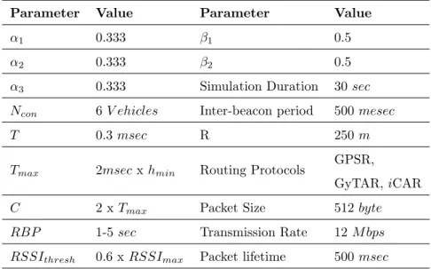
3.1 Simulation Parameters for iCAR Evaluation . . . 42
4.1 Simulation Parameters for iCAR-II Evaluation . . . 69
5.1 Simulation Parameters for D-CAR Evaluation . . . 100
List of Figures
1.1 VANET Structure . . . 2
1.2 Research Stages . . . 8
1.3 General Network Model . . . 11
2.1 Taxonomy of Routing Protocols in VANETs . . . 15
3.1 RSE Control Packet (CP) Fields. . . 34
3.2 VPC Algorithm . . . 37
3.3 Example of VPC operation at the current CP forwarder vm . . . 39
3.4 iCAR Packet Delivery Ratio with PGR = 50 packets/sec . . . 44
3.5 iCAR Packet Delivery Delay with Avg Vehicular Density = 6 veh/lane.klm 45 3.6 iCAR Communication Overhead. . . 46
4.1 Defining Driving Directions . . . 52
4.2 An Example Case with Two Mobility Scenarios . . . 58
4.4 Approximate simulation map . . . 68
4.5 Average delay for network information dissemination within a road segment using beacons . . . 71
4.6 Probability of initiating RSE procedure for a vehicle entering the road segment 73 4.7 Average RLL in a road segment . . . 74
4.8 Percentage of Connected Road Segments to the Core Network using iCAR-II 75 4.9 Average Packet Delivery Ratio (P DR2) using 4 RSUs and PGR = 10 pack-et/sec . . . 77
4.10 Average Packet Delivery Ratio (P DR2) using 4 RSUs and vehicle density of 70 vehicle/lane.klm . . . 78
4.11 Average Packet Delivery Delay (P DD) using 4 RSUs and PGR = 10 pack-et/sec . . . 78
4.12 Average Packet Delivery Delay (P DD) using 4 RSUs and vehicle density of 70 vehicle/lane.klm . . . 79
4.13 LTE Routing-Control Messages . . . 81
4.14 Average LTE Routing Messages per Vehicle per Hour . . . 81
5.1 The Simulated Area around University of Waterloo . . . 99
5.2 Correlation between the NNs outputs and the Target ES with W = 10 sec 101 5.3 Percentage of Connected Road Segments to RSUs with W = 15 . . . 103
5.4 Average CRT in the Network with 2 RSUs . . . 103
5.5 Percentage of Buffered, Sent, and Received Data packets with 2 RSUs and W= 15 Seconds . . . 105
5.6 Average Packet Delivery Ratio with 2 RSUs . . . 105
5.7 Average Packet Delivery Delay with 1 RSU and low data traffic . . . 107
List of Nomenclatures
m, n, o, q Indices for vehiclesi, j Indices for intersections
vm A vehicle with an identifierm
Ii An intersection with an identifier i
ei,j A road segment between two adjacent intersections Ii and Ij
κ An index for mobility scenario
z, ω Indices for routing paths
Pz(i) A routing path with an identifierz from intersection Ii to the core network
OBU On-Board Unit
RSU Roadside Units
LCs Location Centres
CPs Probe Control Packets
N Ns Neural Networks
N SI Network Status Information.
LRT The minimum predicted Link Residual Time
Qi,j Road segment ei,j score
CRT The minimum predicted Connectivity Residual Time
T ablevm The routing table for vm
R The transmission range for line-of-sight cases
ˆ
R The transmission range for non-line-of-sight cases
Locvm Cartesian coordinates ofvm location
Sm The reported average speed of vm
um The velocity vector ofvm
ESm The predicted future speed of vm
LSm The average speed ofvm’s leading vehicles
Smax Averaged maximum speed
LVm Set of leading vehicles for vm
W The predicting time window
Sigm The turning signal status of vm
Dirm A binary variable indicating the driving direction of vm
RSSIm The RSSI value of vm
km Vehicular density in front of vm
fm A binary variable indicating if vm is a front vehicle
lm A binary variable indicating if vm is a leading vehicle
Hm A binary variable indicating if vm is moving towards a common intersection
dm,n Distance between two vm and vn
dm,i Distance between two vm and Ii
N Set of neighbouring vehicles
N Set of potential forwarders
L,F,R Sets of adjacent road segments representing left, front, and right road seg-ments respectively
Mm Set of vehicles between two control packet forwarders
Lm Set of LRTs with vehicles ∈Mm
Cm,n Set of common neighbouring vehicles between vm and vn
P Set of available routing paths
K Set of possible mobility scenarios
PRSE Probability of initiating a road segment connectivity evaluation procedure
pSD Probability of sending probe packets to measure road-level delivery delay
Last B Timestamp for the last mobility information update in the outgoing beacon messages
τBt Time period for updating mobility information in the outgoing beacon
mes-sages
τLinkU pdate Time period for updating neighbouring vehicles mobility information in
rout-ing tables
Last U pdvi Timestamp forvm mobility information update
vel Change in speed threshold to update a neighbouring vehicle’s mobility
infor-mation in routing tables
Di,j The experienced road-level packet delivery delay for ei,j
Chapter 1
Introduction
1.1
Vehicular Ad Hoc Network
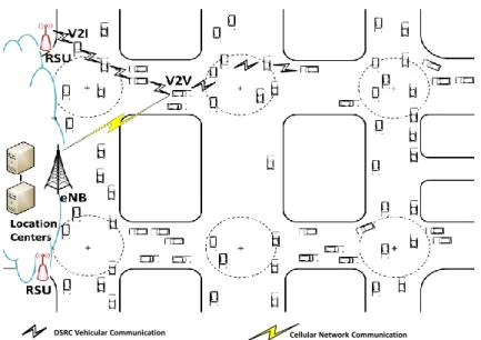
Vehicular Ad Hoc Networks (VANETs) are emerging networks that employ wireless com-munication technologies to enable vehicles to communicate with one another, and with other communication networks. In VANETs, each vehicle is equipped with a network-ing device, On-Board Unit (OBU), to enable Vehicle-to-Vehicle (V2V) communications. Similar devices, Roadside Units (RSUs), are spread along the road sides to allow Vehicle-to-Infrastructure (V2I) communications. RSUs works as gateways to infrastructure, data repositories, or packet repeaters. Figure1.1 shows the basic structure of VANETs.
VANETs have attracted the attention of both research and industrial communities, which is reflected in the interest of governments and standardization organizations. Euro-pean car manufacturers have instituted the Car-to-Car Communication Consortium (C2C-CC) [1] to improve road safety and efficiency. The U.S FCC (Federal Communication Commission) has approved a 75 MHz spectrum for vehicular networks in the 5.9 GHz
V2I
RSU OBU
V2V
Internet
Figure 1.1: VANET Structure
band [2]. In 2008, the European Telecommunications Standards Institute (ETSI) has also allocated 30 MHz of spectrum in the same band for Intelligent Transportation Systems (ITS). In 2014, the U.S. Department of Transportation (DoT) National Highway Traffic Safety Administration (NHTSA) began taking steps to enable V2V for safety purposes [3]. The Institute of Electrical and Electronics Engineers (IEEE) also supports VANET with the IEEE 1609 family of standards for wireless access in vehicular environments (WAVE).
VANET is characterized to be decentralized and has short transmission range for its nodes. The permissible power levels of VANET give the communication signals a range of 1 km with a range of data rates between 6 and 27 Mbps [4]. VANET is a large-scale network that is frequently disconnected or partitioned, and has a highly dynamic topology, due to the high mobility of the vehicles. The network density is temporally and spatially changing. On the other hand, the mobility of VANET’s nodes can be modeled and predict-ed because vehicle’s movements are constrainpredict-ed by streets, and follow prpredict-edictable mobility
patterns. The two entities comprising VANETs, OBUs and RSUs, have sufficient com-putation, energy, and storage capabilities. Moreover, VANETs have hard packet delivery delay constraints, especially for safety applications.
The development of VANET is a direct response to the increasing demands of ITS services, the expectations of the automotive industry, the evolution of the Internet of Things (IoT), and the increasing demand for mobile data. Thus, VANET is designed for a wide range of applications related to safety, traffic management, and passenger comfort.
Safety applications are the main motivation for the development of VANETs. VANETs are used with the goal of spreading accurate data quickly and reliably, in order to avoid ac-cidents and loss of life. In VANETs, vehicles help to avoid acac-cidents through cooperation; they inform one another about their own source-of-risk behaviour, such as highway merg-ing, and they also disseminate emergency warning messages when a hazardous status is detected, such as slippery road conditions. VANETs also improve road safety by enabling traffic lights and signs to communicate with vehicles.
In addition to safety applications, VANETs are also employed in a variety of ITS traffic management applications. Road traffic management applications focus on improving traffic flow in order to avoid traffic congestions, to reduce travel time, and to utilize the trans-portation infrastructure effectively. Examples include adaptive traffic lights that change according to the status of the traffic in an intersection, and direction information based on real-time traffic information.
A third type of VANETs applications can be classified as entertainment and infotain-ment applications. Transferring files between vehicles, accessing the Internet during trips, finding a nearby point of interest, and disseminating advertising messages about a near-by business are all examples of expected VANETs services. Recently, the deployment of
VANETs to enable vehicular Internet-based services, such as TCP-based (e.g., WWW, e-mail), FTP and P2P, and mobile data offloading is envisioned to be a promising solution for the growing demand of mobile Internet access and the anticipated mobile data explosion problem in cellular networks [5, 6].
1.2
Unicast Routing in VANETs
Designing an efficient routing protocol is required for mult-hop communication in VANET-s, to deliver data packets from vehicles to RSUVANET-s, from RSUs to vehicles or from vehicles to other vehicles, when the sender and the receiver are not within the communication range of one another. Different from other networks, vehicles’ high mobility and the frequent change of communication links between vehicles make the traditional topology-based routing pro-tocols, such as AODV [7] and DSR [8], fail in VANETs as they flood the network with path finding and maintenance control messages [9]. Replacing this node-level network topology routing, vehicular communication researchers have introduced an alternative geographi-cal location-based routing paradigm, or position-based routing (PBR), which depends on routing packets among geographical locations by arbitrary nodes, instead of routing among pre-determined nodes, in order to cope with the vehicular network environment. Studies confirm that this paradigm, PBR, outperforms topology-based routing in both urban and highway VANETs scenarios [9][10].
In PBR, packets are forwarded hop-by-hop toward the destination location. The rout-ing decision at each intermediate forwarder is determined with respect to the position of the destination, the position of vehicles within the transmission range (neighbouring nodes), and the forwarding strategy of the protocol. Thus, each vehicle should be able to obtain its geographic location, e.g., by GPS, and share it with its one-hop neighbours. In general,
PBR protocols consist of three components: 1)Beaconing: broadcasting a periodic mes-sage that includes the geographic location of the vehicle; 2) Location Service: defining a methodology that enables a source vehicle to obtain the location of a non-neighbouring destination; and 3) Forwarding Strategy: defining the strategy to select the next hop among neighbouring vehicles, or a next geographic anchor, toward the destination location.
Although many PBR protocols have been proposed for VANETs, as will be shown in Chapter 2, there are still some major challenges and limitations in PBR that need to be addressed. First, PBR depends on opportunistic forwarding where the existence of a communication path between the source and destination is not guaranteed, neither is the optimality of the chosen route. Only destination location and local information are available to a source vehicle prior to the start of transmission, as it is difficult for each vehicle to obtain full network connectivity information in the highly dynamic large-scale VANETs. Second, the majority of PBR protocols have not considered a realistic location service and assumed the availability of destination location in their performance evaluation. Obtaining destination location via an alternative network, such as cellular or sensor networks, can increase the communication cost, while using pure ad hoc network for location service can affect the network performance. The delay encountered by routing a location update sent by a destination, an enquiry message sent by a source, and a response message sent by a server or an agent, significantly affects the accuracy of the delivered information.
Third, most PBR protocols tend to select roads with dense vehicular traffic for a bet-ter network connectivity which causes data traffic congestion. Routing protocols should consider more factors in their forwarding strategies and path planning for better routing performance. Fourth, for Internet access and mobile data offloading, vehicles need instant information about connectivity to the core network before transmission. This information
includes the existence of at least one routing path to an RSU gateway, in addition to the expected quality and duration of the connection. Since PBR protocols do not support this information, a new routing paradigm is required for Internet-based services in VANETs
1.3
Research Motivation and Objectives
From the aforementioned promising applications of VANET’s multi-hop communications, VANET is envisioned to play an important role in road user safety, intelligent transporta-tion systems (ITS), users comfort as well as addressing the expected sever problem for cellular network overload due to the ever increasing demand of mobile data. This research is motivated by the fact that designing an efficient routing protocol is still a key chal-lenge for multi-hope communication in VANETs including Internet access and mobile data offloading. Our objective is to design a protocol for VANETs that dynamically and proac-tively finds long-life connected paths to the infrastructure, with reduced delivery delay, and supports vehicles with this connectivity information.
Connectivity information will assist the different applications to make their transmission decision: start data packet transmission via VANETs, reschedule the transmission, or transmit via alternative network if applicable. Supporting VANET users with instant connectivity information, such as the existence of a route (or more) to the core network, the duration of this connection, and the expected packet delivery delay via this route, will not only improve the routing performance, but also preserve the network bandwidth and improve the overall VANETs performance.
With respect to the special characteristics of VANETs, our design strategy to extract connectivity information is based on utilizing the locally available real-time mobility infor-mation, sending dedicated probe messages when needed, as well as deploying static map
information, in order to predict connectivity among vehicles and to the core network. Thus, we are aiming to answer the following questions:
1. How to find the remaining link lifetime between two mobile vehicles in the city scenario?
2. How to determine whether a vehicle is connected, via multi-hop routing, to the core network or not, and in case of a valid connection, what is the remaining lifetime of that connection?
3. How to support vehicles with instant and dynamically updated connectivity infor-mation?
1.4
Summary of Research Contributions
This thesis follows three steps to address the routing challenges in VANETs, that have been highlighted in Section1.2, and give answers to the technical questions in Section 1.3:
Step 1: Supporting VANET users with instant broad connectivity information to surrounding road intersections
Step 2: With the assistance of cellular network, supporting VANET users with instant comprehensive connectivity information to RSUs
Step 3: Supporting VANET users with instant comprehensive connectivity infor-mation without the assistance of other networks
Broad Connectivity Awareness in VANETs
Cellular Network-Assisted
Comprehensive Connectivity Awareness Comprehensive Connectivity Awareness in VANETs
Figure 1.2: Research Stages
We define broad connectivity to be the existence of at least one path to route packets between two adjacent intersections, i.e., road-level connectivity. Comparably, we define comprehensive connectivity to be the existence of at least one path from a vehicle to a gateway RSU. Figure1.2 describes our steps to meet the research objective in this thesis. With respect to these steps, three routing protocols have been proposed,iCAR,iCAR-II, and D-CAR. In followings, thesis contributions are summarized accordingly.
1.4.1
i
CAR: Junction-to-Junction Connectivity Aware Routing
The intersection-based connectivity aware routing protocoliCAR is an improved version of the existing position-based routing protocols, and an important base for the other proposed protocols. Similar to the existing protocols,iCAR has not considered the connectivity to the core network and assumed the location service to be available. However, it supports vehicles with connectivity information to adjacent intersections and assigns scores to the connected ones for better PBR decisions. iCAR introduces the following algorithms:messages
• Ranking road segments for efficient next-junction selection
In iCAR, we study some key parameters in routing such as considering road-level delivery delay as a routing parameter, the dynamic updating of adjacent road segments’ ranks, the selection of next packet forwarder, and the distribution of routing information.
1.4.2
i
CAR-II: Cellular Network Assisted VANET Routing
iCAR-II is a novel infrastructure-based connectivity-aware routing protocol that deploys cellular communication for routing purposes in order to achieve comprehensive connectiv-ity awareness for VANETs. Unlike PBR protocols, vehicles obtain instant connectivconnectiv-ity information including routes to RSUs and start overlay source routing by the means of intersections. iCAR-II deploys distributed algorithms to obtain real-time location and mo-bility information in order to estimate a minimum broad connectivity lifetime and experi-enced packet delivery delay per road segment, and updates location centres using cellular network channels. Thus, location centers can construct a city-level dynamically updated network view, or a real-time network topology, and support inquiring senders with up-to-date connectivity information, routing paths to gateways, and destination locations. Updated comprehensive connectivity information are exchanged at intersections to proac-tively reach VANET users. iCAR-II includes the following contributions:
• A heuristic methodology to obtain a minimum communication link duration between each pair of communicating vehicles
• A distributed and dynamic routing that utilizes the introduced algorithms for efficient data routing and manages a cooperative operation between cellular networks and VANETs
1.4.3
D-CAR: Distributed Overlay Routing with Comprehensive
Connectivity Awareness
D-CAR is a dynamic connectivity-aware routing protocol that supports vehicles with in-stant comprehensive connectivity information to the infrastructure. Unlike iCAR-II, D-CAR does not use cellular network channels. Connectivity information is carried forward and constructed from each RSU to every connected road segment. In addition to more accurate link residual time information between communicating vehicles, D-CAR enables vehicles to proactively find alternative paths, by the means of intersections, with different connection duration and expected delivery delay. D-CAR includes the following contribu-tions:
• A neural network based short-term speed prediction module for accurate speed pre-diction within a given time window
• An improved mobility prediction based minimum link lifetime estimation between communicating vehicles
• A dynamic connectivity awareness module that describes the procedures to construct different paths from each RSU to every connected intersection, the remaining con-nection duration for each route, and the expected packet delivery delay using these routes
DSRC Vehicular Communication Cellular Network Communication
Figure 1.3: General Network Model
1.5
Network Model
The network model considers hybrid VANETs in an urban environment. VANETs consist of OBUs installed within vehicles’ systems, and RSUs installed at the major city intersec-tions. OBUs are able to obtain geographic location, mobility vectors, and turning signal status information, to share it with nearby vehicles. Periodic local sharing of driving condi-tions, e.g., every 100 msec, via beaconing messages is required for safety applications [11]. RSUs are VANETs gateways to the core network, i.e., Internet. Multi-hop forwarding is enabled to extend the coverage of RSUs and allow non-neighbouring vehicles to access the core network. Vehicles participate in multi-hop forwarding using their own OBUs, i.e., have sufficient inducements to forward packets belonging to other vehicles. All OBUs are synchronized and have access to identical digital maps with well-defined road segments, driving directions, and intersections.
As urban area is considered, road segments are bounded by controlled intersections and have variable length, width, and vehicles densities. The general network model is presented in Figure 1.3. In addition to the VANET, the model includes cellular networks eNBs and a set of location servers on the core network forming Location Centers (LCs). Cellular communications are considered only in our second proposed protocol, iCAR-II. Location centers play an important role in PBR and in our design as well. They receive a huge amount of updates, maintain updated network topology and vehicles locations, and respond to vehicles’ inquiries. LCs can consider a design of distributed location servers that matches the geographically distributed nature of VANET. For example, a city-road map can be divided into a number of vicinities and each server is responsible for one or more vicinities. Adjacent vicinities can exchange their real-time road-level network topology to have a wider network view, and a proper hierarchical server architecture will enable obtaining any destination’s location in the network. The details of LCs physical design such as map division and servers’ management and allocation are out of our scope, and LCs will be considered as one logical unit in our system.
1.6
Thesis Outline
This thesis is organized as follows:
• Chapter 2 provides the background material and related work for this research. As the proposed protocols integrates mobility prediction and routing in the vehicular environment, this chapter covers mobility models and routing protocols in VANETs. The chapter reviews the related work in three areas: (1) Internet access and mobile data offloading in VANETs; (2) Mobility Prediction based Link Lifetime Estimation in VANET; and (3) position-based routing protocols.
• Chapter 3 presents our proposed protocol iCAR. It includes a description of its four components followed by the performance evaluation of the proposed protocol. The four components consisting iCAR are: (1) Road segment evaluation ; (2) Validity period calculation; (3) Next-junction selection; and (4) Next-hop selection.
• Chapter 4 presents our second routing protocol, iCAR-II. This protocol is presented with respect to its four components: (1) Beaconing and neighbourhood awareness; (2) Mobility-based link lifetime estimation; (3) Road segment connectivity estimation; and (4) City-level network topology and data packet routing. iCAR-II performance evaluation is followed.
• Chapter 5 introduces the third routing protocol, D-CAR. D-CAR consists of three modules: (1) Neural networks based link lifetime prediction; (2) Network connec-tivity prediction; and (3) Data packet routing. A performance evaluation section is presented after the details of D-CAR.
• Chapter 6 highlights the thesis findings and major results. This chapter also gives some insight on interesting and challenging directions for future research.
Chapter 2
Background and Related Work
———————————————————-2.1
Routing Protocol Classification
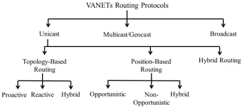
A routing protocol describes the procedure that two communicating entities, that are not in communication range of each other, use to exchange information. This includes the rules to establish a route, the strategy of forwarding data packets, the action to maintain the route, and the procedure to recover from a routing failure. In general, routing protocols are classified according to communication pattern into three main categories: unicast, multicast and broadcast [9, 10, 12]. Unicast routing is the operation of performing data communication from a single source to a single destination via a single route. In contrast, multicast is the operation of delivering the same message from a source to a group of members. If the intended members are identified by their geographic location, the routing is identified as geocast. Broadcast is the operation of disseminating the same message from
Figure 2.1: Taxonomy of Routing Protocols in VANETs
a source to all network members. Our focus in this thesis is on unicast routing protocols in VANETs.
Figure2.1 shows a general classification of VANETs routing protocols. Many protocols have been proposed for different applications and scenarios. In the following, we describe some important features and attributes that a routing protocol can characterized by and classified accordingly. In literature, two common routing paradigms are used for multi-hop wireless routing, the traditional topology-based routing and the position-based routing [9, 10,13]. Topology-based protocols require full path information where every communi-cation entity maintains a routing table. Path information is acquired either pro-actively or on demand (reactive routing). On the other hand, PBR protocols require only thelocation
information of the transmitting node, its neighbouring nodes and the destination node. According to the data type and delivery requirements, PBR protocols can be further di-vided into opportunistic, non-opportunistic, and hybrid routing protocols. Opportunistic routing is designed for delay tolerant networks (DTNs) which consider intermittent con-nectivity, while non-opportunistic routing considers the existence of at least one path and is designed for dense networks. Hybrid protocols are designed for partial network
con-nectivity. Below, we highlight the differences between these strategies and describe some other important features and attributes that a routing protocol can be characterized by and classified accordingly.
Proactive and Reactive Routing
Most traditional topology-based routing protocols are proactive (table-driven), reactive (on-demand) or hybrid. Topology-based protocols use information for existing links in the network to determine the route. In proactive routing, nodes maintain a routing table to all other reachable nodes (destinations). Constructing and maintaining the table requires constant broadcast of control packets. In VANETs, proactive protocols (e.g., FSR [14]) use significant amounts of the available bandwidth to keep available lookup table but provide low latency due to the absence of route discovery or destination locating procedures. In contrast, reactive routing finds a path between two entities only when needed, and main-tains routes in use only. Typically, reactive routing protocols (e.g., AODV [7], DSR [8]) use a route discovery procedure to find a path between source and destination before starting data packets transmission. Query packets are flooded into the network to find the best path to a certain destination. Reactive protocols define the way to control this flooding and to maintain the link between the end entities. Hybrid topology-based routing proto-cols (e.g., ZRP [15]) maintain available neighbourhood routing information in a proactive manner and use the discovery phase of reactive routing as needed. Many research works [9, 10,13] show that topology-based routing does not perform well in VANETs and has a scaling problem.
Opportunistic and Non-opportunistic Routing
PBR makes the routing decision based on the geographic position information of nodes. PBR is more robust and promising in VANETs as the links state information exchange and maintinance of existing links information are not required. PBR protocols can be clas-sified into opportunistic and non-opportunistic routing protocols. Opportunistic routing protocols (e.g., VADD [16]) consider VANET as a Delay Tolerant Network (DTN) where the link existence between source and destination is not guaranteed and the vehicles de-pend on their physical movement to deliver packets. Vehicles store, carry and forward packets to a closer vehicle to the destination, or a vehicle that has a better opportunity to carry packets to that destination. A recent study [17] has considered using buses and taxis to disseminate data in VANETs using external storage units at intersections working as ”drop boxes”. On the other hand, non-opportunistic routing assumes the existence of a path between source and destination (e.g., GPSR [18]). Thus, when a packet reaches a vehicle with no neighbour closer to the destination than the vehicle itself according to the forwarding strategy, the forwarding strategy is considered to have failed and a recovery strategy is required to deal with this failure. This failure is called local maximum as the forwarding strategy has made the maximum local progress for the current vehicle. Hybrid routing protocols apply a combination of opportunistic and non-opportunistic routing; for example, using opportunistic routing as a recovery strategy for a non-opportunistic routing protocol.
Anchor-based and Node-based Routing
VANETs routing protocols can be classified into anchor-based routing and node-based routing, which are also called overlay and non-overlay routing. In node-based routing, the
routing protocol operates at the node-level and the routing decision is taken by individual nodes (e.g., GPSR [18]). On the other hand, an anchor-based routing protocol (e.g., A-STAR [19]) operates on some particular anchors overlaid on the top of the network. Anchors can be geographic locations that have high importance in the routing decision such as road intersections. Thus, the design of anchor-based routing protocol considers routing at anchors and routing between them. Routing between anchors is usually the simple greedy routing, where the next-hop is the closest node to the next intersection, while routing at anchors considers a variety of forwarding strategies and next anchor selection parameters.
Source Routing and Distributed Routing
In source routing, the path between source and destination that packets should traverse is determined by the source node. The source appends the path information to the packet header by means of a set of node IDs (e.g., AODV) or geographic anchors (e.g. GSR [20]). On the other hand, distributed routing protocols take the routing decision at each node or anchor. A hybrid routing protocol is also possible by considering source routing with flexibility to update the path on-the-fly (e.g., DSR [8]).
Offline Information Based Routing and Real-time Information Based Routing
In PBR, packets are forwarded to neighbours that are closest to their final destinations or have a better chance to deliver them. Recent protocols consider a higher level of view by taking into consideration road maps and junction information. The selection of the road segment that a packet should traverse or the next anchor depends on the forwarding strategy of the protocol. PBR protocols make their decision of selecting the next hop or next anchor based on a variety of parameters and information. Based on the information
required to select the forwarding path, advanced PBR protocols can be further classified into two categories: offline based routing protocols and real-time information-based routing protocols.
Offline information-based routing protocols utilize static information, such as city maps, road width, and bus routes, or statistical information, such as average traffic density at certain time for each road, in order to assign weight for different network’s edges and select the best routing path accordingly. Protocols with the assumption of availability and accuracy of such information (e.g., VADD [16]) outperform the ordinary PBR protocols.
On the other hand, recent PBR routing protocols use real-time traffic information to dynamically route packets toward a destination via paths having better momentary conditions (e.g. GyTAR [21]). Obtaining real-time traffic information is a challenge for this type of protocol; however, real-time traffic information-based routing protocols can outperform statistical information-based routing protocols especially when the variance of the statistical information is high. For example, in the case of car accidents or road closures due to constructions, real-time traffic information helps the protocol adapt to the current road condition and maintain its routing performance.
2.2
Vehicular Mobility
The unique characteristics of vehicular mobility influence the complexity of VANET stud-ies. The high speed of vehicles, the constrained mobility patterns, the temporal and spatial variation in vehicles densities, and the clustering of vehicles at intersections are examples of these characteristics. Vehicles movement is restricted by roads, traffic rules, speed limits, and sometimes, the movement of surrounding vehicles. In addition to traffic engineering fields, these phenomena have been studied by technology developers to capture a level of
realism in simulating vehicles movement for better validation of new technologies. Thus, a large variety of mobility models have been proposed for different purposes and needs.
A mobility model is a systematic description of a node’s movement; how it changes its speed, acceleration, and mobility direction over time. In literature, vehicular mobility models can be classified, according to the level of details of the interaction between vehi-cles and the required/provided information, into three classes: macroscopic, mesoscopic, and microscopic [22]. Macroscopic models considers gross quantities, such as vehicular density and average speed of vehicles, and deal with vehicular traffic according to fluid dynamics. On the other hand, microscopic models consider individual vehicles mobility and pay attention to the driver behaviour and the interaction between vehicles [23]. The level of details in the mesoscopic models is located in the middle between macroscopic and microscopic models. For example, in mesoscopic models, individual vehciles are considered and charectrized independentally and identically [22].
As the previous classification seems to be very broad, the available mobility models have been categorized differently in literature [22,23,24]. Mobility models vary in defining parameters related to city maps, vehicular traffic generation, trip sources and destinations, trip trajectories, vehicle categories, human driving behaviours, intersection management, and more. Models have been designed for one or more of these attributes, and larger projects include comprehensive models and different engines for optional model selection. Following is a list of the main categories for developing mobility models for vehicular mobility:
Synthetic Models: The most well-know category which considers developing mobility models based on mathematical models to reflect realistic vehicular physical movement.
design-ing a generic mobility model that is able to reproduce the observed behaviour.
Trace-based Models: In which generic mobility models are extracted from movement traces. This type of model generating becomes more common as it is faster, less complicated than synthetic models, and many projects started to make trace data available.
Traffic Simulator-based Models: Some commercial companies and research teams have developed realistic traffic simulators using sets of complicated synthetic models. These simulators, such as SUMO [25] and VISSIM [26], have been verified by real traces and survey data and showed the ability to simulate urban microscopic vehicular mobility.
In addition, synthetic models can be further classified into five classes [27]: Stochastic Models which include models with pure random movement, Traffic Stream Models which consider fluid hydrodynamics for vehicular mobility, Car Following Models which consider the effects of the vehicles ahead on the driver’s behaviour, Queuing Models roads and vehicles as FIFO queues and entries respectively, and Behavioural Models which consider a set of behavioural rules, such as social influences, to determine the vehicle’s movement. Below is a briefly illustrate a basic car following model.
Car Following Mobility
In car following mobility (CFM), the behaviour of the vehicle movement is related to the vehicle, or a group of vehicles, ahead. The fundamental basic rule is to keep a safe distance ahead. CFM models fall in the microscopic category where the details of individual vehicle mobility is considered. In CFM models, the vehicle location, velocity and acceleration are functions of different inputs, stimulating its mobility pattern, such as the distance to the front vehicle and the current speed of both vehicles. Other inputs in different models increases the level of realism considered, such as the driver’s attitude and reaction time
and the characteristics of the vehicles under consideration. CFM models often describes rules for lane changing. These models describe vehicle movement in multi-lane highways or independent road segments; however, models becomes more complicated in simulations where stop/priority signs and traffic lights are present.
While most CFM models are time-continuous defined by ordinary differential equations of kinematics, the discrete time framework of Cellular Automaton (CA) is also used in simulations. In CA, the road segment is divided into cells, where each cell is occupied by at most one vehicle. The mobility model then describes the rules of determining the existence and the velocity of a vehicle in a certain cell based on the previous status of the vehicle and the status of the surrounding cells. For example, the following simple algorithm [24] determines the updated speed of a vehiclei after ∆t time units,Si(t+ ∆t),
in a highway lane using CFM based on CA:
Step 1: If Si(t)< Smax then Si(t+ ∆t) =Si(t) + 1
Step 2: If Si(t+ ∆t)≥Cj −Ci then Si(t+ ∆t) =Cj−Ci−1
Step 3: If Si(t+ ∆t)≥1 then with probability ρ : Si(t+ ∆t) = Si(t+ ∆t)−1
In the first step, a default acceleration is applied by increasing the speed one unit, every time unit, until reaching a maximum speed Smax. The second step accounts for breaking
when reaching a leading vehicle j, where Ci and Cj denote the cells occupied by vehicle i
and vehiclejrespectively. The third step includes the randomness of the driver’s behaviour. After determining the speed of vehicle i, its location is updated to be Ci +Si(t+ ∆t).
2.3
Related Work
The problem of VANET routing for Internet packets and mobile data offloading is a recent research trend, and few studies have considered its various challenges. On the other hand, mobility prediction-based connectivity-aware routing in VANETs is a renewed research area that has been investigated by different researchers. Therefore, related studies can be divided into three parts: 1) studies that consider Internet access and data offloading in VANETs, 2) studies that deploy mobility-based link lifetime prediction to improve routing in VANETs, and 3) studies that consider analytical methods for efficient PBR routing in VANETs.
2.3.1
Internet Access and Mobile Data Offloading in VANETs
The idea of drive-thru Internet, where moving vehicles obtain low-cost Internet access from roadside access points, was introduced by Ott and Kutscher in [28]. After that, several studies have considered Internet access and mobile data offloading using VANETs [29,30,31,32,33,34,35,36,37,38,39, 5]. The feasibility and throughput of one-hop V2I Internet access are studied in [29,30, 31, 32]. Then, cooperative download from an access point on a highway is proposed in [33] to show the feasibility of maximizing the portion of downloaded data from the Internet via multi-hop cooperation. In [34, 35], different strategies to optimize RSUs placement are proposed to improve the performance of multi-hop Internet access in VANETs. In [36], a survey of Internet access routing protocols in the vehicular communication environment is provided. In [5,37,38,39], the Internet access in VANETs is studied from the perspective of cellular data offloading.Authors in [29] and [32] analytically investigated the troughput of one-hop drive-thru Internet. In [29], the throughput of V2I Internet access is studied with reference to the
impact of road density, vehicle speed, service penetration rate, and RSUs transmission range. This throughput is further studied in [32] with an optimal access control to boost it. The throughput is enhanced by selecting an optimal transmission region within an RSU’s coverage for the coordinated medium sharing of all vehicles. In addition, the MAC DCF is also considered in [30] and [31]. In [30], Tom Luan et al. studied the effect of vehicle’s velocity on the drive-thru Internet and, accordingly proposed different DCF models to enhance its performance. Similarly, Miao Wang et al. studied the effect of neighbouring vehicles’ density on the one-hop drive-thru Internet and proposed a density-adaptive MAC protocol for better Internet access performance.
Enabling multi-hop Internet access via RSUs has been considered for the highway s-cenarios in [33] and for the urban scenarios in [34] and [35]. In [33], closer vehicles to RSUs are selected to be forwarders as they can achieve faster downloads via I2V; then, the downloaded packets are forwarded to their final destinations via V2V communication. The proposed algorithm has shown to provide a maximum download and minimum delay for cooperative downloading. Both [34] and [35] have analytically studied the problem of RSU placement in VANETs, where the objective is to deploy the minimum number of RSUs while meeting certain QoS requirements. In [34], the maximum distance that an RSU can cover for delay-tolerant data packets and real-time data packets are studied differently and the planning has been done accordingly with respect to the data packet delivery delay as a QoS constraint. On the other hand, Hassan Omaret al. have shown in [35] the feasibility of multi-hop Internet access via RSUs placement strategy considering the probability that a vehicle can find a network path to a gateway, which is based on the traffic conditions in the deployment region.
The potential of VANETs for cellular traffic offloading is studied in [5,37,38]. A survey of the general mobile data offloading techcniques was provided in [5], while the challenges,
research issues and possible sollutions related to the effectiveness of data offloading in the vehicular environment are discussed in [37]. In [38], the authors show that 100% of mobile data flows can be offloaded via multi-hop VANETs with the availability of link and connectivity information.
2.3.2
Mobility Prediction based Link Lifetime Estimation in VANET
The utilization of mobility prediction for long-lived routes was established early for mobile ad hoc networks (MANETs), such as in [40] and [41], where position information was used for reliable routing. In VANETs, the mobility patterns have unique characteristics, and the estimation of a link lifetime or a connection residual time based on vehicular mobility prediction becomes a new challenge. In literature, deterministic methods, such as in [42,
43, 44, 45, 46] and stochastic methods, such as those in [47, 48, 49] have been proposed to estimate link lifetime between two vehicles, or path lifetime between a source and a destination. The estimated link duration information have been deployed to construct routing paths in few protocols such as in [43] and [45].
Deterministic mobility prediction based link residual time estimation methods either utilize the position and velocity vectors information of nearby vehicles or consider cross layer parameters for mobility prediction. In [42], [43], and [46], information related to position, speed, and driving direction are used to calculate the time required for two com-municating vehicles to move out of each other’s communication range. Driving direction is either estimated using the velocity angle of a moving vehicle or by applying its position to a digital map. In [44] and [45], vehicle’s mobility information is assumed to be unknown. Alternatively, a series of received signal strength indicator values, or signal to noise ratio, collected from each neighbouring vehicle are used to predict the residual link life time.
The collected link quality indicators form a time series for each nearby vehicle, and the remaining time before the link quality drops below a certain threshold is estimated.
On the other hand, link duration has been studied analytically in [47,48,49]. Key mo-bility parameters, such as the distribution of relative velocity, are considered to determine the expected link lifetime. In [47], the distribution of the signal-to-noise ratio is used in order to predict the probability that a link is broken in a certain time. Cellular Automata (CA) concept is used in [48] to provide an analytical framework to study key connectivity parameters such as link duration, connectivity duration, and re-healing time. The distri-bution of relative velocity is used in [49] to predict the relative velocity and estimate the link residual time. In addition to relative velocity, authors of [49] have considered traffic lights and turning vehicles as the main causes of link breakage.
Utilizing link residual time awareness, few studies have considered end-to-end connec-tivity and constructing long lifetime routes such as in [42, 45,47,50]. In [42], vehicles are grouped according to their driving directions and paths are constructed among vehicles from the same group with longer link residual time for more stable routes. The link du-ration estimation method proposed in [45] has been evaluated using a modified Dijkstra’s algorithm. In [47], a reactive protocol is used to find a node-based path from a source to destination using link duration between vehicles as weights. In [50], the link duration estimation proposed in [43] has been combined with GPSR [18] for a better greedy routing performance.
2.3.3
PBR Protocols
It has been shown eailer in this thesis that PBR paradigm is more suitable in the vehicular context than the traditional topology-based routing. One of the fundamental protocols
that deploys PBR for mobile environment is GPSR [18]. GPSR uses Greedy forwarding
where packets are forwarded to nodes that are closer to the destination. When this strategy fails, GPSR usesPerimeter forwarding as a recovery strategy, where packets are forwarded around the perimeter of the failing region. In addition to the geographic location required by GPSR, other protocols, such as [20, 19, 51, 21], consider the availability of further network information for better routing performance. GSR [20] is an overlay routing that uses digital maps information and deploys source routing, where the shortest path, by the means of intersections, is attached to each packet. A-STAR [19] is another overlay source routing protocol that uses a statistically rated map for street-traffic aware routing. On the other hand, TIGeR [51] and GyTAR [21] are distributed routing protocols which deploy real-time vehicular traffic information for intersection-based traffic aware routing, where routing decisions are made at intersections based on local vehicular traffic information obtained from each road.
The functionality of GPSR, GSR and GyTAR routing protocols are described below as examples of PRR protocols that have been widely used as performance benchmarks for new protocols evaluation. GPSR represents the family of distributed node-based routing protocols. GSR, on the other hand, represents the family of source anchor-based routing. GyTAR is a distributed anchor-based routing protocols. While GSR uses offline map in-formation, GPSR and GyTAR use real-time inin-formation, where GPSR deploys one-hope neighbouring vehicles position information and GyTAR deploy road-level traffic informa-tion. Thus, these protocols covers the different important aspects in routing as presented in section 2.1.
GPSR
GPSR (Greedy Perimeter Stateless Routing) [18] is a well-known PBR protocol developed originally for mobile ad hoc networks (MANETs). GPSR uses position information of one-hop neighbours exchanged in beacons to make greedy forwarding toward the destination position. GPSR requires one-hop topology information to make a local forwarding decision in addition to the destination location. GPSR greedy forwarding strategy defines the next forwarder as the progressively closest immediate neighbour to the final destination. When this strategy fails, i.e., there is no neighbour closer to the destination than the current node, GPSR uses a recovery strategy by routing around the perimeter of the failing region. As many other PBR protocols, GPSR does not specify a location service to obtain the destination position.
As a PBR routing protocol, GPSR performs well in scenarios with highly dynamic topology, such as in VANETs, as it does not require full path finding or maintaining op-erations. However, greedy routing in the VANETs context causes multiple local minimum events where GPSR recovers by forwarding in perimeter mode, in which a packet traverses successively closer faces of a planar subgraph of the connected VANET, until reaching a node that is closer to the destination than the position that the perimeter mode started at, where greedy forwarding is resumed. This causes a major increase in the number of intermediate forwarders and, accordingly, the end-to-end packet delivery delay.
GSR
In order to address the node-level routing challenge in the highly dynamic topology of VANETs, GSR [20] uses source PBR. By utilizing map information and planning the routes by the means of consecutive junctions, GSR overcome the problem of traversing high
in-termediate forwarders presented in GPSR. In GSR, the route is calculated using Dijkstra’s algorithm to find the shortest path in the graph between a source and a destination. The graph is the city road map with bidirectional edges representing roads, and graph-nodes representing road intersections. Edges in GSR are not rated and only the location of the source and destination locations are required in addition to the map information. Each data packet has the full route included in it’s header fields. Intermediate forwarders use greedy routing to select the next-forwarder in order to deliver packets independently to the next-junction indicated in their routes.
Although GSR is using a shortest path algorithm, the connectivity of these paths are not ensured. GSR does not use statistical or real-time traffic information to rate the map, while planning the path, which affects its performance. In dense networks and limited data traffic streams, GSR performs well and shows low delivery latency. However, in light-traffic areas, GSR fails to discover connected routes and shows low packet delivery ratios. Moreover, as GSR applies static routing, it can easily cause data traffic congestions on some road segments.
GyTAR
The improved greedy traffic-aware routing protocol, GyTAR [21], is an intersection-based routing protocol that uses real-time traffic information to dynamically select path inter-sections. In GyTAR, road maps are represented as junctions and road segments. Each segment is divided into a number of equal-size cells. Considering cells centres as anchors, particular vehicles leaving a road generate cell density packets (CDP) and forward them to the other end (intersection) through the road’s anchors in order to collect vehicle density information. At the other end, another group of vehicles calculates the average and the variation of vehicle density per cell and disseminates the results in the intersection. Packets
are forwarded from an intersection to another where the next intersection is selected based on the vehicle density information and the curve metric distance between the adjacent intersections and the final destination.
GyTAR uses an improved greedy forwarding between intersections where senders esti-mate the current location of their neighbours, before selecting the next forwarder, using velocity vectors information exchanged in beacons. This enhancement in the greedy for-warding strategy is to avoid selecting a forwarder that has already left the sender’s trans-mission range or became no longer the most progressive next hop due to its mobility dur-ing the inter-beacon interval. As a recovery strategy, GyTAR considers carry-and-forward techniques to overcome the local maximum problem of greedy routing.
GyTAR is a heuristic routing approach that utilizes map information and local vehicle traffic information within the neighbouring intersections to improve routing performance. It performs better than static information based protocols such as GSR and A-STAR. GyTAR suffers from the local vehicle traffic awareness problem. The forwarding decision is taken at each intersection considering traffic density to the adjacent intersections only. In some cases, this limited vision causes packets to be bounced between two intersections or forwarded via unoptimised roads causing higher delivery delay. Also, selecting dense roads for data forwarding and path planning causes data traffic congestions and high queuing delay which degrades the network performance.
Chapter 3
i
CAR: Intersection-based
Connectivity Aware Routing
———————————————————-In this chapter, we propose an intersection-based connectivity aware routing protocol (iCAR), which combines static map and real-time traffic information, in order to improve VANET performance in city scenarios. iCAR calculates an adaptive lower bound of broad connectivity lifetime, which enables better routing decisions based on guaranteed connec-tivity information to the adjacent intersections, with a minimized cost of communication overhead. For each road, iCAR takes into consideration both vehicular density and aver-age communication delay. Thus, roads with high data volume and high vehicular density have a low preference to be selected as forwarding paths, in order to avoid an increased average transmission delay. As a result, a fair distribution of packets is achieved across the network, and the overall network performance can be improved.
lo-cation and does not consider comprehensive connectivity awareness. In the following, we describeiCAR in Section3.1 in terms of its four components: a) Road Segment Evaluation (RSE), b) Validity Period Calculation (VPC), c) Next-junction Selection, and d) Next-hop Selection. Next, we present a simulation-based evaluation and discussion of the results in Section3.2. The chapter is summarized in Section 3.3.
3.1
i
CAR: Protocol Description
iCAR combines local real-time road condition information and static road-topology in-formation extracted from digital maps. Real-time inin-formation is locally and dynamically calculated at each road, by sending out a probe control packet (CP) to discover connec-tivity and collect vehicular traffic information while traversing the road segment. CPs are probabilistically generated at each intersection to maintain updated connectivity informa-tion. Scores are assigned to each road segment, based on the volume of vehicular traffic in that road and the delay experienced by the associated CP. After that, the scores are disseminated locally in beacon packets exchanged by vehicles at the intersections. The beacons also include the validity period of each score.
Two routing strategies are employed: next-junction selection and next-hop selection. Packets are forwarded from junction-to-junction based on the next-junction selection s-trategy, and forwarded hop-by-hop within roads based on the next-hop selection strategy. Accordingly, we describeiCAR by its four components as follows:
3.1.1
Road Segment Evaluation (RSE)
RSE is a heuristic distributed approach aimed at evaluating the broad connectivity of road segments, as well as their suitability to be selected in packets routing paths. It also maintains a global parameter that enables the fair and accurate distribution of packets. RSE procedure is carried out by a vehicle vm entering to a road segment ei,j. vm triggers
the RSE with probability PRSE, where PRSE is a function of the road segment conditions
and the remaining lifetime of the road scoreQi,j. When RSE is triggered, vm transmits a
unicast discovery packet (CP) to the center of the next road intersection. CP is forwarded hop-by-hop according to the next-hop selection strategy. Figure 3.1 shows the lightweight packet format of CP. Upon reception of CP, each forwarder (including vm) accumulates
in the field Ntotal the number of vehicles located between itself and the vehicle chosen as
the next forwarder. The origination time and the number of hops h are also recorded in CP. The forwarder runs Validity Period Calculation (VPC) algorithm (described in Section
3.1.2) and updates the lifetime field if it has a shorter estimated link lifetime, before sending the packet to the next hop.
When CP reaches the next intersection, the closest vehicle to the center of the inter-section, sayvn, is responsible of generating the updated score Qi,j. vn then announces the
score across the intersection, and sends it back to the location where the RSE procedure was triggered. Qi,j is calculated by vn as follows:
Qi,j =α1·min 1,Navg Ncon +α2· T tavg +α3· hmin h , (3.1)
whereNavg is the average number of vehicles per one hop transmission distance, Ncon is a
constant representing the average number of vehicles per one hop transmission distance, based on statistics of city scenarios, T is the minimum one-hop transmission delay (i.e.,
Figure 3.1: RSE Control Packet (CP) Fields
the delay of transmitting a similar packet with no buffering delay and perfect channel conditions),tavg is the average per hop transmission delay of the CP,hmin is the minimum
number of hops required to traverse the road segment, h is the number of hops actually traversed fromvm tovn, andα1,α2 and α3 are weighting factors for the vehicular density,
the one-hop transmission delay, and the number of intermediate forwarders, respectively.
The delivery of CP at the next intersection indicates the instantaneous connectivity of the road. The information stored in CP helps the vehicle at the target intersection to assign a road score with a validity period (or lifetime) for such a score. As shown in Equation
3.1, the effect of the vehicular density on the score is upper-bounded by α1, and Navg is
calculated as follows:
Navg =
Ntotal
h . (3.2)
The average delay per hop indicates the delay due to both queuing in the forwarders’ buffers and retransmissions. tavg is calculated as follows:
tavg =
(t2−t1)
h , (3.3)
time, respectively.
Vehicles with variable dimensions may work as obstacles for transmission, and may reduce the effective transmission range in their vicinity [52]. A large number of obstructing vehicles result in shorter effective transmission ranges, and hence, a higher number of intermediate transmissions. iCAR reduces the score for road segments with relatively high number of intermediate forwarders, as shown in Equation 3.1. The minimum number of forwarders,hmin, is calculated as follows:
hmin =dl/Re, (3.4)
wherel is road segment length and R is transmission range.
When vm triggers the RSE procedure, it sets a timer Tmax and waits for reception of
the returningQi,j or another CP coming from the other side. If vm does not receive such
information before the timer expires, then vm sets the score to zero. If a forwarder does
not find a next-hop during the forwarding of CP, it sends the CP back to the originator with an indication of road disconnection. Qi,j is also set to zero in such a case. The Qi,j
is announced across the intersection and a random validity period (RBP), which works as a backoff period, is set to prevent multiple CP transmissions.
The probability PRSE that vm triggers the RSE procedure when entering the road
segment is designed in a way that the score, Qi,j, is refreshed when it has a long validity
period, and to allow re-computing the value before the current validity expires. SinceiCAR considers not only the road segment connectivity, but also the packet delivery delay at the moment ofQi,j calculation, the renewing ofQi,j before the expiration time is beneficial. In
Equation 3.5, we present one way to calculate PRSE, where trem is the remaining validity