1
Model-Based Systems Engineering Pilot Program at NASA
Langley
Kevin Vipavetz1
NASA Langley Research Center, Hampton, VA, 23681 Douglas Murphy2 and Samantha Infeld3
Analytical Mechanics Associates, Inc., Hampton, VA, 23666
NASA Langley Research Center conducted a pilot program to evaluate the benefits of using a Model-Based Systems Engineering (MBSE) approach during the early phase of the Materials International Space Station Experiment-X (MISSE-X) project. The goal of the pilot was to leverage MBSE tools and methods, including the Systems Modeling Language (SysML), to understand the net gain of utilizing this approach on a moderate size flight project. The System Requirements Review (SRR) success criteria were used to guide the work products desired from the pilot. This paper discusses the pilot project implementation, provides SysML model examples, identifies lessons learned, and describes plans for further use on MBSE on MISSE-X.
I. Motivation
Model-Based Systems Engineering techniques are used in the SE community to address the need for managing the development of complex systems. A key feature of the MBSE approach is the use of a model to capture the requirements, architecture, behavior, operating environment and other key aspects of the system. The focus on the model differentiates MBSE from traditional SE techniques that may have a document centric approach. In an effort to assess the benefit of utilizing MBSE on its flight projects, NASA Langley has implemented a pilot program to apply MBSE techniques during the early phase of the Materials International Space Station Experiment-X (MISSE-X).
MISSE-X is a Technology Demonstration Mission being developed by the NASA Office of the Chief Technologist i . Designed to be installed on the exterior of the International Space Station (ISS), MISSE-X will host experiments that advance the technology readiness of materials and devices needed for future space exploration. As a follow-on to the highly successful series of previous MISSE experiments on ISS, MISSE-X benefits from a significant interest by the
1 Lead Systems Engineer, MISSE-X, NASA Langley Research Center, Management Systems Office D2A, Engineering Directorate, [email protected].
2 MBSE Lead Engineer, MISSE-X, NASA Langley Research Center, [email protected], AIAA senior member.
3
Deputy Systems Engineer, MISSE-X, El Cerrito, CA, [email protected], AIAA senior member.
science and engineering community. New features of MISSE-X will address customer needs based on prior MISSE history, and reduce return mass in the post-shuttle era.
The goals of MISSE-X present a number of SE challenges. The increased capability and complexity of the platform design over previous MISSEs, a larger and more distributed community of participating investigators, and expanded use of ISS robotics for installation and servicing all contribute to a greater need for systems-level vigilance. The pilot aimed to implement MBSE techniques, including the development of a model using the Object Management Group (OMG) Systems Modeling Language (SysML), to help the SE team address these challenges.
The deliverable work products for the pilot were identified based on the success criteria defined by NASA for the Systems Requirements Review (SRR). The SRR is a gate in the project life cycle that ensures that the system requirements and interfaces have been properly identified, and that at least one feasible design has been proposed.
The specific process improvements sought by this pilot program included
1. centralized access to integrated information about the structure, behavior, requirements and performance of the MISSE-X system,
2. consistency in documentation created from the model,
3. confidence in the ability of the design to satisfy all stakeholder requirements and project goals,
4. improved communication among the development team project stakeholders, and 5. the advancement of MBSE and SysML skills at LaRC.
This paper describes the tools and methods used during the pilot program (Section II), reviews the preliminary results in terms of the five process improvement areas (Section III-VII), and identifies plans for next steps (Section VIII).
II. Tools and Methods
The implementation of MBSE during the pilot program was focused on capturing the system specification and requirements in preparation for the MISSE-X SRR. While development of multi-disciplinary simulations or linked executable models was not part of the scope of the pilot, the SE team did seek to gain insight into the viability of using a SysML model for serving as an integration framework for such simulations. The system specification was implemented using a SysML model, and requirements were managed using a relational database. The SysML model was developed using the MagicDraw application from No Magic Inc. MISSE-X requirements were captured and managed using the CORE application from Vitech Inc. Both of these tools allowed the project data to be stored on a version controlled, remotely accessible database that enables concurrent development by multiple users.
In cases where requirements needed to be instantiated in the SysML model, they were imported from CORE. While a single integrated system was clearly preferred, a viable single application was not identified by the project. Existing expertise on the team with MagicDraw, existing use of CORE on similar projects at LaRC, and a lack of features by any one tool to
3
directly with the CORE and SysML databases, and SE products such as documents and presentations were prepared by exporting content from the databases.
The Object Management Group describes SysML as general-purpose graphical modeling language for specifying, analyzing, designing, and verifying complex systems that may include hardware, software, information, personnel, procedures, and facilities4. Developing a SysML model consists of creating model elements, defining relationships and connections between these elements, and (optionally) creating diagrams using these elements. During the pilot, the model was updated either by group consensus during working group meetings or by individual engineers working directly on a particular section of the model tree in the shared database. An early benefit of the modeling activity was that the effort required to build appropriate SysML elements required consensus on the system architecture and on naming conventions for MISSE-X features and functions.
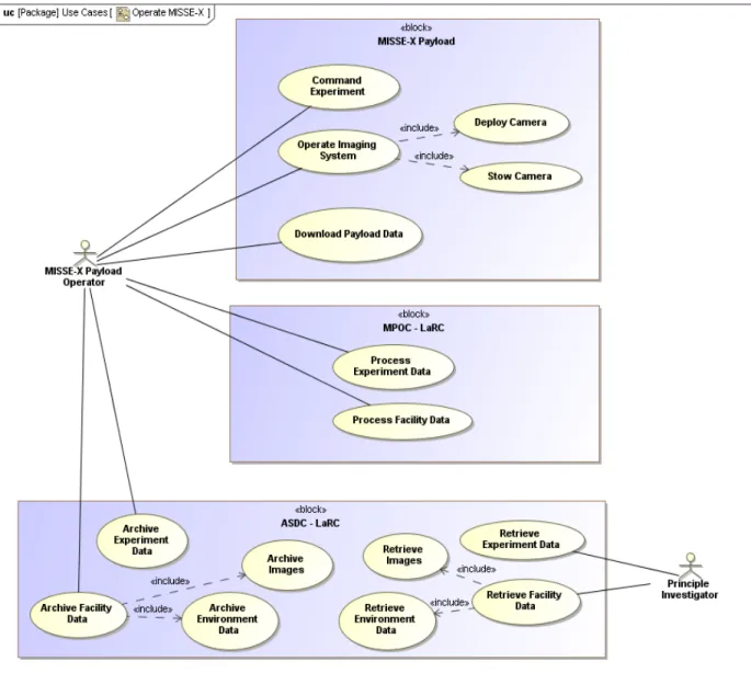
The SysML model development process largely followed the Object Oriented SE method. Use-case diagrams were created to capture stakeholder interaction (Figure 1), and activity diagrams documented the system functions (Figure 2). Next, we defined the system architecture and external boundaries using a package diagram (Figure 3). Consensus on a well defined system architecture benefitted the development of the concept of operations (ConOps) and the definition of system interfaces. An internal block definition diagram was used to show flows and interfaces between systems (e.g. of data in Figure 4).
Figure 1. A SysML Use Case Diagram. The activities of the MISSE-X Payload Operator and a Principle Investigator are shown.
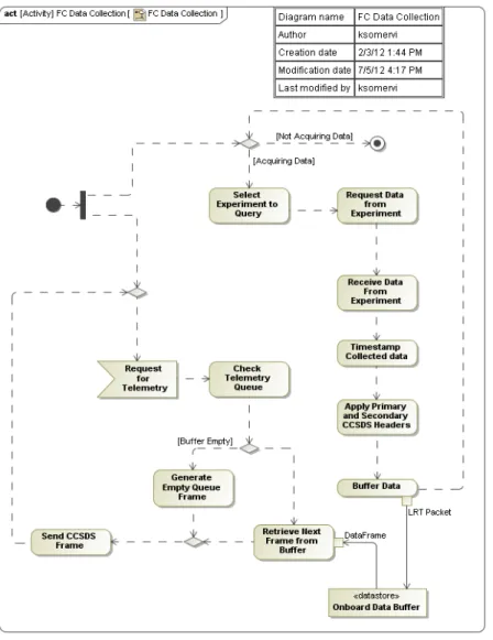
Figure 2. Activity diagram of a facility controller’s data collection function.
5
Figure 3. A SysML Package Diagram depicting the MISSE-X Systems Architecture. The connections between the system-of-interest (blue boxes) and external/enabling systems (green boxes) defined key external interfaces.
More in-depth physical structures (using block definition diagrams), operational flows (using activity diagrams), and internal interfaces (using internal block diagrams) were created to visualize the system from particular points of view. These helped ensure the MISSE-X team had a shared understanding of the system structure and function as it was being developed. Figures 5 through 8 below are a few examples of lower level diagrams.
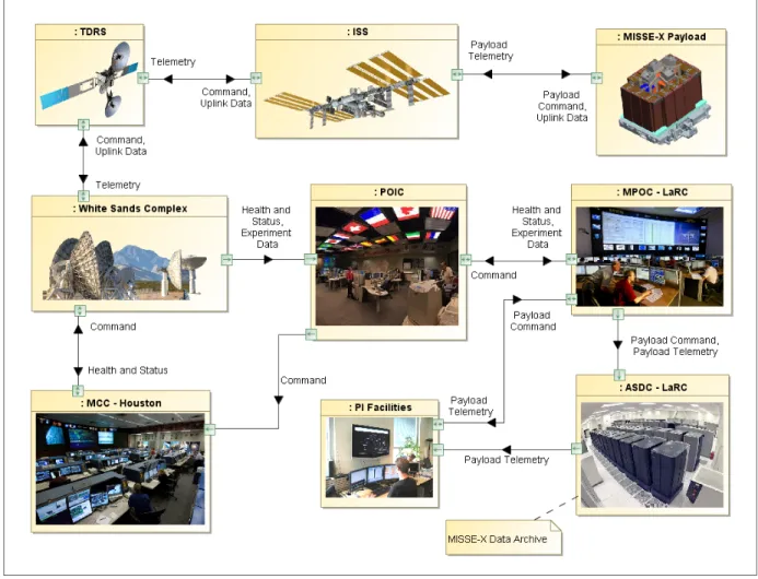
Figure 4. Internal block diagram showing the communications flow through the system and external supporting elements.
Figure 5. Block definition diagram showing the composition of the payload’s physical structure. CAD models of the system components were utilized to improve the comprehension of the assembly concepts and naming conventions.
Figure 6. Activity diagram of a day in the life of MISSE-X operations. This diagram helps define what functions are performed daily, where the function is performed, and how it flows into the next function.
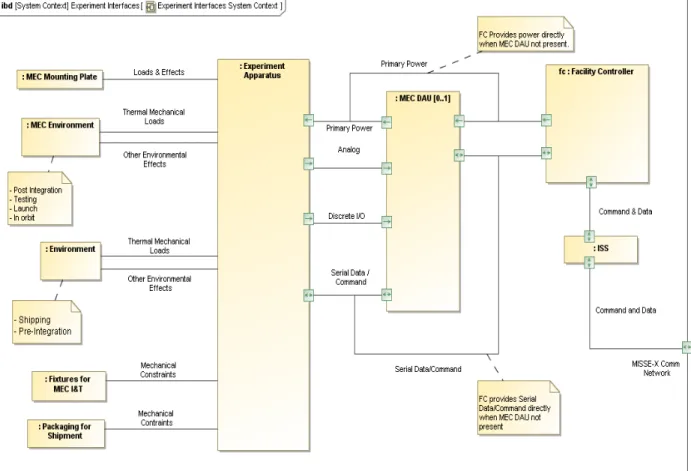
Figure 7. Internal block diagram showing the interfaces with experiment apparatus. This diagram helped define and communicate the resources, constraints, and environment that will affect experiments on MISSE-X.
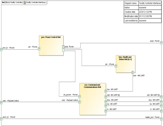
Figure 8. Internal block diagram showing the internal interfaces of a Facility Controller. The path of power and data between the major avionics components on the MISSE-X facility is shown. This internal block diagram is part of the avionics design process, a different use for the same type of SysML diagram as in Figure 7.
III. Centralization
While the use of separate databases for the SysML model and requirements model prevented the realization of a single centralized repository of integrated information, the benefits of using a shared database approach over a document-based system were still evident. One conclusion of the SysML authors was that the advantages of using a shared repository of information are as applicable to systems modeling as they are to software development and other collaborative activities. A variety of SysML diagrams were used to document the system concept of operations as well as some assembly, integration and test activities. While functional flow block diagrams or ad-hoc approaches may have sufficed to document the operations concepts, the use of SysML
comprehension of the context and dependencies of the system, especially as the design details are filled in.
The development of the SysML model guided the working discussions and prompted technical questions that helped identify requirements, mature the system design and document risks. The single instance of information containing the MISSE-X structure and behavior was especially useful when the system concept was in flux, since it provided a consistent point-of-departure for comparing proposed changes or alternate concepts. The activity diagram for the MISSE-X transportantion concept (Figure 9), for example, was developed initially by MISSE-X engineers and iterated with ISS program experts to document this important interface.
Figure 9: Activity diagram of the transportation concept for the initial launch of MISSE-X and a subsequent resupply mission. Swimlanes identify locations of the activities and SysML central buffer nodes are used to represent MISSE-X hardware.
Use of SysML to document the system of interest and its interfaces was also beneficial in checking the completeness in the system level requirements in CORE. Several users authored and edited requirements and their relationships directly via the CORE user interface with write access to the central database. Other stakeholders involved in requirements development worked with the CORE users to have their input added to the database. As a single repository for requirements and directly connected elements, the CORE model contained the most current version of requirements, their allocations, owners, and verification methods. The CORE content was periodically exported as a web-site so that all team members could view the requirements without the CORE client. In preparation for SRR (as planned for all key project milestones), the mature content in CORE was exported to requirements documents that were placed under
configuration control. The change request process ensured that revisions were properly reflected in updates to the documentation.
Compared to collections of presentations, meeting notes, documents, and ad-hoc drawings, the SysML and CORE databases were advantageous in terms of providing access to complete and current information. The combination of these repositories allowed each system requirement to be traced back to the motivating objectives and system functions, and exposed gaps where functions had not yet been captured by requirements. Challenges to realizing these access improvements included the need to find appropriate methods for making the content available to users without the client applications, identifying appropriate methods for configuration control, and coordinating the development of the information inside the database with information from other team members that was not being generated with either MagicDraw or CORE.
IV. Consistency
While reducing the duplication of technical content in different documents is a standard SE guideline, it is difficult to implement completely. The desire to express information consistently when it appears in multiple places was especially important during our pilot program. Because MISSE-X was in a formulation phase, the opportunity to misinterpret a re-wording or alternate expression of a concept as an intended change frequently arose. In SysML, re-use of the elements from hierarchical model in different figures benefits consistency of the graphical representations. Element names, for example, are represented identically in any diagram where the elements appear. In early formulations of the system architecture when MISSE-X terminology had not yet solidified, the use of the model in working meetings and documents helped improve consistency in communications. The payload structure diagram in Section 2, Figure 5, was an important figure for terminology consistency.
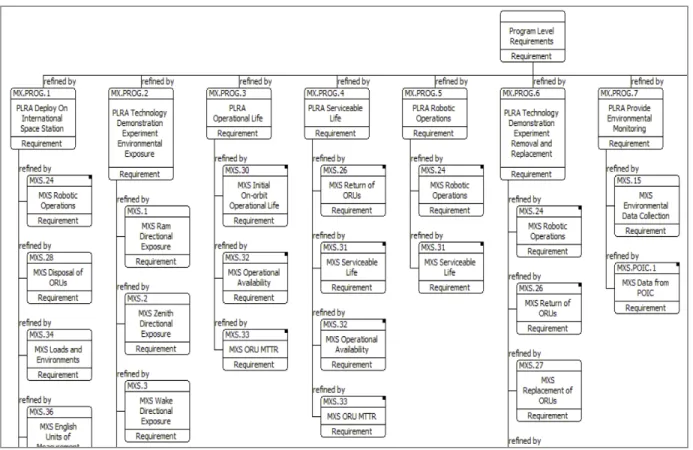
The known benefits of using a centralized database to ensure consistency in requirements management has motivated the use of CORE on a number of projects at LaRC, including MISSE-X. Like MagicDraw, CORE maintains relationships between model elements (requirements) and allows multiple representations of those relationships. Representations may be in the form of a requirements traceability diagram (Figure 10), a list of requirements assigned to a particular owner, or an interface control document, all different views of the same system model. Exports of content from CORE were used frequently to disseminate information to the MISSE-X team, with the understanding that changes needed to be made to the database itself, rather than the exported content, in order to maintain configuration control.
Figure 10. CORE requirements traceability diagram portion, showing the flow from program to system requirements.
While the manual export and import process to copy requirements from CORE to MagicDraw did not substantially impact the consistency of our model during the pilot, this area is seen as a potential hazard. As new subsystem and verification requirements are developed and linked to the model, the need to propagate changes from CORE to MagicDraw will increase. Addressing this issue is future work for the pilot team.
Also, the configuration control techniques used to manage the content in CORE were not entirely applicable to the SysML model. The ability of CORE to store the project document template, including boilerplate sections such as the MISSE-X Glossary and Acronyms, enabled the requirements manager to export complete documents directly from the tool. Any later revisions to the content in CORE were therefore guaranteed to appear correctly in subsequent document exports. By contrast, SysML content was exported as individual diagrams which were embedded into configuration controlled documents. Synchronization of subsequent updates to the model with later document releases was therefore a manual process. Further, because SysML model elements are frequently used in multiple diagrams, unintended and unnoticed side effects in the diagrams can occur when modifying elements in the model.
V. Confidence
MISSE-X used MBSE to help illustrate a ‘feasible’ system design that would satisfy all the requirements and goals of the project at SRR. This effort required, in the view of the SE team, a two-part assessment of our system. The first assessment was of the technical feasibility. This
required confirming that the design can be implemented within the project cost and schedule constraints to a level of confidence consistent with the project risk posture. The second assessment required showing that the design could meet the project goals. Part two, a kind of system validation activity, was accomplished by a successful requirements development process. Both of these activities benefitted from the MBSE approach and development of the SysML model.
The technical feasibility benefitted from the ability of the modelers to communicate the system design effectively at a relatively high level of detail in the areas of greatest complexity. For MISSE-X, the system complexity due to the variety of interfaces was addressed by developing SysML diagrams to effectively capture these interfaces and identify the entities on each side of the interface. The complexity due to the avionics and camera system was addressed in part by developing detailed internal block definition diagrams.
The design validation benefitted from having traceability from the requirements to the project need, goals and objectives. Traceability was implemented in CORE and augmented with the SysML model. In CORE, the traceability was maintained explicitly using the ‘relationship’ of each requirement to identify its parent and children. In SysML, diagrams were developed to capture the specific functions that the MISSE-X design would perform. Use-cases documented, at a high level, the roles of the stakeholders in interacting with MISSE-X. Activity diagrams, state-machine diagrams and sequence diagrams were used to document the intended behavior of the system.
The CORE and SysML models became assets that helped provide convincing evidence that the design was feasible and appropriate for the project need. Presentation materials were developed from the model (including diagram exports) to communicate this evidence to the MISSE-X project stakeholders and the SRR Board.
While overall the SE team experienced a net benefit towards increasing the confidence in our system viability by using the MBSE approach, several challenges were identified. First, there is no guarantee that the model is correct. While the SysML authoring tool enforces some rigor in assembling elements and relationships according to the rules of the SysML specification, it is easy to create a fully compliant SysML model that misrepresents the MISSE-X system. While a software developer can use a compiler to execute his code and compare the results against the expected outcome, the SysML author codifying some aspect of the system of interest does not have an equivalent way to check the ‘code’. Anyone learning a new programming language quickly understands the difficulty of writing correct code, for even the simplest algorithm, without feedback from the compiler or the program output. The SysML author in most cases (with the possible exception of parametric models) does not have an equivalent feedback loop, and relies on evaluation by colleagues fluent in the language to verify the model implementation. In a project where familiarity with SysML is limited, such verification becomes more difficult. Simple executable parametric models (e.g. a mass rollup) were briefly attempted using the Paramagic Plugin for MagicDraw. Strict naming conventions required by parametric solver prevented re-using the existing architecture model elements in the parametric diagrams; therefore these samples were done in separate stand-alone models. The drawbacks of having separate models (or converting the existing model to the less user-friendly element names) drove us away
15
classes that will allowing the model to smoothly evolve. Our team had several restarts in creating the meta-model since the shortcomings of a particular design often do not show up until new elements are added. As in software development, planning for throwaways of the very early models may be appropriate. We concur also with Shafto et al.iii who advocate for a "library of [SysML] models [that] would provide a way for the engineers to design a new spacecraft by assembling existing models that are domain specific, and therefore easy to adapt to the target system."
VI. Communications
Advancing the quality of communications between team members on the project was a key goal of this pilot. A standard specification for depicting the functions and features of a technical project involving diverse stakeholders has obvious benefits, and was part of the motivation for the development of the UML system on which SysML is based5. One challenge facing the pilot was also obvious: learning a new language is not trivial. The results of the pilot so far have yielded both predicted benefits and incurred the predicted costs in this regard. Overall we believe the rigor of the SysML diagrams has provided a positive return on investment towards improving communications, though our assessment is only qualitative.
The immediate benefit of using SysML to codify the MISSE-X system is that, if done properly, the SysML model language is made less ambiguous than unrestricted prose or ad hoc diagramming approaches through assumptions and constraints. The semantics of SysML allow the model developer to express succinctly and precisely the design or behavior under consideration. Further, model elements re-used in different diagrams (e.g. the ISS and the LaRC Operations Center) have a consistency in their features (including name, interface ports etc.) because they come from the same source. The resulting presentation graphics used for working meetings or out-briefs eventually benefitted from this consistency as the SysML technique became more familiar to the viewers.
On MISSE-X the SysML model development occurred in two ways: either a domain expert with SysML knowledge added elements to the model directly, or an engineer with SysML knowledge translated ad hoc diagrams or other content provided by a domain expert into model elements. While both of these activities benefitted MISSE-X, the first method exposed, we believe, the potentially dramatic increase in the efficiency and quality of technical communications using SysML. In the case of MISSE-X, the avionics team and the Systems Engineering team were able to ‘converse’ via the model directly. The management of interfaces particularly benefitted from this relationship, since many of the details of the ISS interfaces and MISSE-X facility-to-experiment interfaces are documented in the avionics model.
While not as efficient, the mode in which a SysML author engages a domain expert to jointly develop a model had, we believe, a side benefit to the project. The activity of capturing the system design or behavior in a formal language motivated the model developers to think about the system in an object-oriented way, and even proved beneficial in developing appropriate names for MISSE-X components to properly communicate their behavior in the system.
Communication to external stakeholders faced the hurdle of the SysML symbols being potentially unfamiliar to the target audience. To mitigate this, some care was taken to ensure that
5
Introduction to OMG's Unified Modeling Language™ (UML®), http://www.omg.org/gettingstarted/what_is_uml.htm
the concepts being presented and the symbols used were limited and focused. As the technique became more familiar, the need for this was reduced.
Another pitfall for potential new SysML users, in our view, is the temptation to use the SysML authoring system as a replacement for Powerpoint. While the ability to export figures from the model was valuable, the best results were achieved when the goal of building re-usable SysML elements took precedence over the need to produce a particular kind of figure. Further, the SysML authoring tool interface worked well for viewing the model interactively, but often required extensive re-working of the default presentation options (e.g. font size, line width etc.) to produce an acceptable presentation slide.
CORE requirement traceability diagrams as seen in Section 4, Figure 10, were used to communicate clearly how stakeholder objectives were being addressed by system requirements and the payload design meeting those requirements, and discuss whether they were being interpreted appropriately at each level. CORE was used to quickly produce customized spreadsheets showing requirement parents, owners, or allocations in order to support discussions at all levels of the project.
VII. Advancement of MBSE and SysML Skills at LaRC
The small pilot team received MBSE training and education in a variety of ways, including attending the MBSE webinars developed by JPL (Dan Dvorak, NASA Systems Engineering Working Group), leveraging existing examples provided by INCOSEiv, CORE training, and sharing lessons learned as the project progressed.
Others on the MISSE-X team were exposed to the MBSE activity by working with members involved in the pilot directly or by seeing the work products from the pilot. Because of the roles and responsibilities of the members on the MISSE-X project involved in the pilot and the particular stage of the MISSE-X project life cycle during which the pilot occurred (phase A), the most mature parts of the SysML model are in the overall architecture of the system of interest, the top level interfaces, and the avionics subsystem. As such, we have at present a relatively well-defined high level view of the system, with significant avionics details available at the subsystem level and below. While this divide was more a result of the available resources and immediate needs of the team rather than the result of a specific approach to modeling, it did have several benefits. First, the most experienced SysML authors were able to populate the model early with well-formed ‘examples’ that served to guide the other authors. As a consequence, the most complex pieces of the model (interfaces and avionics) received attention first, a benefit to risk mitigation. As the project advances, we expect that the SysML focus will move to connecting these high and low levels of detail, as well as addressing other concerns as described in section 8: Next Steps.
For institutions such as LaRC that have a document-centric configuration control process, MBSE techniques represent a challenge for synchronizing document versions with the models. A model-centric process in which the model itself is controlled, and from which documents can be produced as desired to review the content, will be better suited for a fully implemented MBSE environment. Such a process could reduce the effort required to produce correctly structured and properly formatted documentation, while focusing the energy of the reviewers on the technical
17
advantage. The benefit of improving the efficiency of communication by leveraging a standard language and a common model, even at a coarse level where the project architecture and key behaviors are described, seemed to stand out during the execution of our pilot.
VIII. Next Steps
At the time of the writing of this article, the MISSE-X project was transitioning to Phase B, in which the subsystem requirements are refined and the design matures in preparation for a Preliminary Design Review (PDR). Our plan for the pilot is to shift the focus towards three new areas: 1) support for the development of MISSE-X Design Reference Missions (DRMs); 2) identifying and documenting verification activities; and 3) developing Views and Viewpoints in the model.
Support for the development of DRMs is expected to include more detailed activity diagrams and internal block definition diagrams that capture the end-to-end data flow between the MISSE-X Payload Operations Center at LaRC and the MISSE-MISSE-X payload on ISS. The path includes a number of waypoints of interest to the avionics and ground systems stakeholders including the Payload Operations and Integration Center at Marshall Space Flight Center, the control room at Johnson Space Center, the payload multiplexer/demultiplexer on the ISS, the Facility Controller onboard the MISSE-X payload (seen in Figures 2 and 8), and the data acquisition system that connects individual experiments on MISSE-X to the Facility Controller. The types of uplinked data that will be modeled include commands (e.g. to take photos, effect mode changes, and update software) to the MISSE-X facility and potentially commands to each of the active experiments on the platform. By modeling these entities in SysML, we hope to gain insight into the process that will benefit the facility design as well as the ground systems implementation and operation.
For the requirements verification process, the SE team expects to use CORE to track each individual verification requirement, and SysML to document the verification activity for some of those requirements. The subset of verification requirements selected for elaboration in the SysML model will include those where the verification activity requires a test procedure, particularly any that have substantial interfaces to other parts of the system (e.g. the various components of the on-board data acquisition system). SysML activity diagrams, internal block diagrams, and sequence diagrams are likely to be leveraged here. The use of CORE in this activity is consistent with our overall desire to have each requirement be traced to a companion verification requirement, which identifies the verification method (inspection, analysis, test or demonstration). The use of SysML is expected to improve the development of procedures and execution of the verification methods (other than inspection) by having a more complete view of the system being verified with respect to the overall system. Diagram exports from the SysML model may also be a source of information for the Verification Compliance Sheets – a form in use by the SE team to document the execution of the verification activity.
Views and Viewpoints are a technique identified by IEEE Standard 1471-2000 (and more recently ISO/IEC/IEEE 42010) to capture the concerns of particular stakeholders and express the model with respect to these concerns. Since the MISSE-X project maintains a database of prioritized risks as well as feedback collected from review boards, a source of stakeholder concerns from which to generate viewpoints is easily accessible. The corresponding views would, we believe, provide some benefit to the current and future SysML developers by providing a logical place to begin viewing the model tree inside the authoring tool.
IX. Conclusion
The MISSE-X SE team undertook a pilot activity to examine the benefit of an MBSE approach applied in the early phase of a NASA project. SysML was used to codify the MISSE-X system, and requirements were managed using CORE. Five specific areas of expected benefit were identified at the outset of the pilot, which focused on developing work products required to succeed at the project System Requirements Review. Preliminary assessments of the results in each area led the pilot team to conclude that the investment of effort in the model-based approach is significant, but can yield significant returns. Challenges included the limited existing knowledge base and best practices for application of SysML in our specific domain, as well as the need to support legacy document-based processes within the project. Use of SysML as an integration layer for simulations in various disciplines was not extensively explored, though developing executable models within the model itself was found to be challenging. Benefits of the SysML approach for describing the MISSE-X system included a more efficient exchange of precise information, especially between stakeholders with some SysML fluency. The pilot team expects the benefits of the MBSE approach to be easier to achieve as the familiarity with the tools and processes increases.
Acknowledgments
Diagrams of the Facility Controller (Figures 2 and 8) were developed by the MISSE-X Avionics lead, Kevin Somervill, who provided SysML guidance to the SE team during this pilot program.
References
i
Thibeault, S.A.; Cooke, S.A.; Ashe, M.P.; Saucillo, R.J.; Murphy, D.G.; de Groh, K.K.; Jaworske, D.A.; Quang-Viet Nguyen; , "MISSE-X: An ISS external platform for space environmental studies in the Post-Shuttle era," Aerospace Conference, 2011 IEEE , vol., no., pp.1-13, 5-12 March 2011
ii
Cole, Delp, and Donahue, “Piloting Model-Based Engineering Techniques for Spacecraft Concepts in Early Formulation,” California Institute of Technology, 2010.
iii
NASA’s DRAFT integrated technology roadmap, Technology Area 11: Modeling, Simulation, Information Technology & Processing Roadmap, Mike Shafto, Chair, URL: http://www.nasa.gov/pdf/501321main_TA11-MSITP-DRAFT-Nov2010-A1.pdf
iv
“Survey of Model-Based Systems Engineering (MBSE) Methodologies,” prepared by the Model-Based Systems Engineering (MBSE) Initiative International Council on Systems Engineering (INCOSE), May 2008;