Procedia IUTAM 14 ( 2015 ) 469 – 478
2210-9838 © 2015 The Authors. Published by Elsevier B.V. This is an open access article under the CC BY-NC-ND license (http://creativecommons.org/licenses/by-nc-nd/4.0/).
Selection and peer-review under responsibility of ABCM (Brazilian Society of Mechanical Sciences and Engineering) doi: 10.1016/j.piutam.2015.03.075
ScienceDirect
IUTAM ABCM Symposium on Laminar Turbulent Transition
Transition control in a three-dimensional boundary-layer flow using
plasma actuators
Philipp C. D¨orr
∗, Markus J. Kloker
Institut f¨ur Aero- und Gasdynamik, Universit¨at Stuttgart, Pfaffenwaldring 21, D-70550 Stuttgart, Germany
Abstract
The applicability of dielectric barrier discharge plasma actuators for controlling the crossflow-vortex-induced laminar breakdown in a three-dimensional swept-wing-type boundary-layer flow is investigated by means of direct numerical simulation (DNS). The first part of the investigation is aimed at modifying the quasi two-dimensional base flow to weaken primary crossflow (CF) instability, mainly due to a reduction of the basic CF. In the second part, the actuators are used to control the three-dimensional nonlinear disturbance state with large-amplitude steady crossflow vortices (CFVs). It is shown for both methods that the amplitudes of the CFVs and the secondary growth of unsteady modes can be reduced and thus transition to turbulence delayed.
c
2014 The Authors. Published by Elsevier B.V.
Selection and peer-review under responsibility of ABCM (Brazilian Society of Mechanical Sciences and Engineering).
Keywords: instability control, transition to turbulence, plasma actuators
1. Introduction
For both environmental and economic reasons improving fuel efficiency is becoming increasingly important for the development of future aircraft. Since potential in further improvement of surface quality, shaping and engines is limited, laminar flow control represents a promising approach. To delay the laminar-turbulent transition in two-dimensional boundary-layer flow caused by Tollmien-Schlichting waves several methods were developed. However, for modern aircraft wings with large leading-edge sweep and three-dimensional boundary layers, transition to turbu-lence is typically caused by CF instabilities. Primary CF instability leads to growth of steady and travelling crossflow vortex (CFV) modes. At low free-stream turbulence conditions as in free flight, steady CFV modes excited by surface roughness typically prevail. The resulting streamwise orientated co-rotating high-amplitude CFVs trigger a secondary instability which rapidly leads to transition to turbulence, see, e.g.,1,2,3.
Aimed at reducing the CF and consequently the primary CF instability, slot-suction systems and suction-hole panels have been used to delay transition since the 1950s4. More recently, a couple of other methods for controlling the
CFV-induced laminar breakdown were developed. Saricet al.5use a spanwise row of roughness elements
(distributed-roughness-elements, DRE) to excite steady ’subcritical’ CFV modes that are spaced narrower than the spanwise
∗Corresponding author. Tel.:+49-711-685-69943; fax:+49-711-685-53402.
E-mail address:[email protected]
© 2015 The Authors. Published by Elsevier B.V. This is an open access article under the CC BY-NC-ND license (http://creativecommons.org/licenses/by-nc-nd/4.0/).
wavelength of the most amplified mode and less unstable with respect to secondary instability to hinder the growth of the most amplified CFV mode. The same concept, however named upstream-flow-deformation (UFD) and not necessarily based on roughness elements, was suggested by Wassermann & Kloker6. An approach combining classical
suction with the UFD concept, named distributed flow deformation (DFD) or formative suction, was proposed by Messing & Kloker7,8 to achieve continual suppression of (secondarily) unstable CFVs in significantly altering base
flows. The pinpoint suction concept proposed by Friederich & Kloker7,9is aimed at controlling the three-dimensional
nonlinear disturbance state with large-amplitude CFVs by applying localized strong suction through holes at the updraft side of the CFVs to hinder the vortical motion and consequently weaken secondary instability.
Plasma actuators were applied to delay transition in two-dimensional boundary-layer flow in lab experiments10,11, flight tests12,13, and numerical simulations14,15. Using an azimuthal array of micrometre-sized plasma actuators
Schueleet al.16successfully excited subcritical stationary CFV modes in a Mach-3.5 boundary layer of a sharp-tipped
right-circular cone at 4.2◦angle of attack, thus hindering the growth of the most amplified mode (cf. DRE/UFD). For the current work we investigate two different methods using plasma actuators to control the CFV-induced laminar breakdown. First, we aim to weaken primary CF instability by reducing the CF of the quasi two-dimensional base flow. Second, we control the three-dimensional nonlinear disturbance state with large-amplitude steady CFVs, cf. the pinpoint suction concept. To model the effect of the plasma actuators a steady body-force distribution similar to that of a DBD plasma actuator is used. The base flow mimics the DLR-Prinzipexperiment G¨ottingen, as also done in3,9, a model flow as it develops on the upper side of a swept-wing at negative incidence within the region of acceleration. It consists of a flat plate with an effective sweep angleΦ∞of 42.5◦and a displacement body above to obtain a nearly constant favourable chordwise pressure gradient (Hartree parameterβH≈2/3).
The paper is organized as follows: §2 presents the numerical method and§3 the base-flow properties and the reference case.§4 and§5 present the results for the two different control methods.
2. Numerical Method
Basic set-up. - For the DNS we use our compressible code NS3D17that has been proven for the investigation
of the crossflow-vortex-induced laminar breakdown9,18. It solves the three-dimensional compressible Navier-Stokes
equations in conservative formulation, whereQ = ρ, ρu, ρv, ρw,ET represents the dimensionless solution vector. The velocity vectoru=[u,v,w]T denotes the velocities in the chordwise, wall-normal and spanwise directionsx,y
andz. Velocities and length scales are normalized by the chordwise reference velocity ¯U∞and the reference length ¯
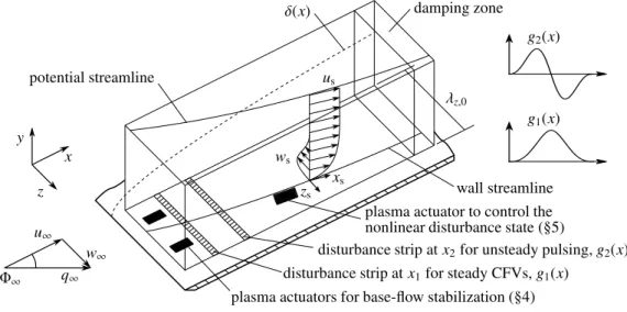
L, respectively, where the overbar denotes dimensional values. Additionally, the reference temperature ¯T∞and the reference density ¯ρ∞are used for normalization. The specific heatscpandcvas well as the Prandtl number are assumed to be constant. Temperature dependence of the viscosityμis modelled by Sutherland’s law. For the simulations a rectangular integration domain on a flat plate is considered, see figure 1. The chordwise and wall-normal directions are discretized using eighth-order explicit finite differences, whereas for the spanwise direction a Fourier-spectral ansatz is implemented to calculate thez-derivatives. For time integration the explicit 4th-order Runge-Kutta scheme is used.
In the experiments at DLR the chordwise free-stream velocity ¯U∞,exp is 14 ms−1, yielding a chordwise Mach number Ma∞,exp ≈0.04. For such small Mach numbers the viscous part of the numerical time-step limit typically dominates and requires a time step proportional toMa2
∞. To allow calculations at a non-prohibitive time step,Ma∞=
0.21 is chosen for the current investigation. At this Mach number, both the temperatureTBand the densityρBvary by
less than 1.6% within the integration domain, ensuring quasi-incompressible behaviour. Flow similarity is ensured by matching theReδ1ranges;δ1- displacement thickness. The reference values ¯T∞and ¯ρ∞are set to 303.4 K and 1.225
kgm−3, respectively. The reference velocity ¯U
∞is chosen at a flow angle ofΦ∞=42.5◦, yielding ¯U∞=we¯ /tanΦ∞=
72.72 ms−1, where ¯weis the spanwise velocity at the upper boundary of the integration domain. Defining the global
Reynolds numberRe=92000 based on ¯U∞and ¯L, the reference length ¯L=0.01923 m is calculated.
The chordwise direction is discretized with an equally spaced grid,Δx=1.309·10−3. For the reference case REF
the domain covers 1.900x5.920 (3072 points). In spanwise direction the fundamental wavelengthλz,0=0.126,
corresponding to the fundamental spanwise wavenumberγ0=2π/λz,0=50.0, is discretized with 32 points (KREF=10
de-aliased harmonics,ΔzREF=3.927·10−3). A shorter domain covering 1.900x4.386 (1900 points) is used for
all the other simulations to afford a finer discretization in spanwise direction. The wall-normal direction is discretized with a stretched grid in the range 0.000 y 0.073 with 93 points andΔywall =2.300·10−4. The time stepΔt
plasma actuators for base-flow stabilization (§4) disturbance strip atx1for steady CFVs,g1(x)
disturbance strip atx2for unsteady pulsing,g2(x) plasma actuator to control the
nonlinear disturbance state (§5) wall streamline g1(x) g2(x) λz,0 damping zone δ(x) potential streamline x y z zs xs us ws u∞ w∞ q∞ Φ∞
Fig. 1. Integration domain and coordinate systems.
is set to 1.575·10−5and the fundamental angular reference frequency toω0=6.0. We use the following boundary
conditions: at the subsonic inflow the base-flow variables are prescribed and upstream-travelling acoustic waves are allowed to leave the integration domain. At the isothermal wall the no-slip boundary condition using dp/dy|wall=0
is employed and ¯Twallis set to ¯T∞. In front of the outflow all conservative variables are ramped to the corresponding base-flow values within a ramping zone 4.341x 4.386. At the free-stream the base-flow values forρandTare kept, whereas du/dy|e=dw/dy|e=0 allowsueandweto adapt. In addition, dv/dy|e=−(d(ρeue)/dx+d(ρewe)/dz)/ρe
is used to calculateve, assuming dρ/dy|e=0.
For postprocessing a streamline-oriented coordinate system (xs,y,zs) is defined wherexspoints in direction of the potential-flow at the upper edge of the integration domain. A tilde is used to mark the respective velocities that are nor-malized by the local base-flow edge velocity in thexs-direction,uB,s,e, hence ˜ws=ws/uB,s,efor example. In addition, a
rotated coordinate system (xr,y,zr) is defined:xr=(x−x0) cosΦr+(z−z0) sinΦr,zr=−(x−x0) sinΦr+(z−z0) cosΦr. Plasma actuator body-force model.- A velocity-information-based empirical model is used to model the plasma actuators by a steady wall-parallel body force19. The dimensionless planar force distribution f(x,y) is defined as
X(x)=a1χ+a2χ2exp(−χ) , χ=(x−xPL)a0, (1a)
Y(y)=b1y+b2y2exp(−b0y2/5), (1b)
f(x,y)=c X(x)Y(y), (1c)
χ,y0; a0,b0>0; a1,2,b1,2,c ∈ R,
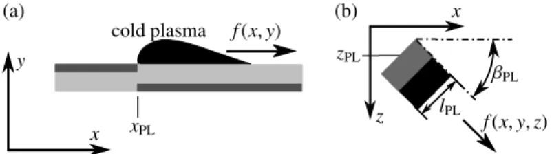
wherexPLindicates the edge of the upper electrode as sketched in figure 2(a). The constantsa0,1,2,b0,1,2andccan
be adapted to define the desired force distribution. The corresponding dimensional force distribution ¯f(x,y) can be calculated according to ¯ f(x,y)= f(x,y)ρ¯∞U¯ 2 ∞ ¯ L = f(x,y) ¯ ρ2 ∞U¯3∞ Reμ¯∞ , (2)
and, for fixedReat constant ¯ρ∞and ¯μ∞for identicalReδ1ranges at different Mach numbers, the dimensional force
scales with ¯U3
∞. Varying Ma∞we investigated the effect of the identical dimensionless force distribution on the
boundary-layer flows. Within the quasi-incompressible range, Ma∞ ≤ 0.3, the same dimensionless force yields basically the same velocity manipulations for all simulations. Only for higher Mach numbers deviations appear. Based on these findings, the dimensionless force distributions used for the Ma∞=0.21 simulations of the present investigations can directly be converted to the corresponding dimensional force distributions for the Ma∞ ≈ 0.04 experiments according to (2).
(a) xPL cold plasma f(x,y) y x (b) z x zPL lPL βPL f(x,y,z)
Fig. 2. (a) Basic 2-d DBD plasma actuator schematic. (b) Discrete plasma actuator rotated with angleβPLabout the wall-normal axisy.
For three-dimensional simulations, the body force produced by a plasma actuator with electrode lengthlPL(cf. figure 2(b)) is modelled by extrusion of f(x,y) along the lateral electrode axis, yielding the force distributionf(x,y,z). At the edges a polynomial of 5th-order is used to smooth the changeover from zero forcing to maximum forcing over a range of 10%lPL. An angleβPL0◦can be defined for rotation of the actuator about the wall-normal axis y, see figure 2(b). In this case the force is split into a chordwise component fx(x,y,z)= f(x,y,z) cos(βPL) and a
spanwise component fz(x,y,z)= f(x,y,z) sin(βPL). Clockwise rotation is defined by positive values ofβPL. The force
components are introduced in the x- and z-momentum equations, respectively, and the work done by the force is accounted for in the energy equation by specifying the scalar product of force and the velocity vector.
The approximation of a steady body force is appropriate. Primary linear stability theory (LST) investigations20of
the base flow yield the most amplified frequencyω0 =6. In case of ¯U∞,exp=14 ms−1,ω0 =6 corresponds to the
dimensional frequency ¯ν0,exp=133 Hz, whereas operating frequencies of DBD plasma actuators and incorporated
disturbances are in the order of several kHz and therefore assumed to be damped out by the boundary layer.
3. Base-flow properties and reference case
Characteristic boundary-layer parameters of the investigatedMa∞=0.21 base flow are shown in figure 3(a). Due to the large sweep angle and the acceleration in downstream direction the flow is strongly unstable with respect to CFV modes. Although the highest amplification rates are found for unsteady modes the focus of the present work is on steady modes due to their typically higher initial amplitudes in low-turbulence environments. For all DNS a disturbance strip at the wall is used with blowing and suction (without net mass flow but with momentum input9) to excite the strongly amplified steady CFV mode withγ=γ0, from now on referred to as mode (0,1) in double-spectral
notation (hω0,kγ0) at x1 =2.22 (lstrip,1 =0.1). To initiate controlled breakdown by secondary instability unsteady,
pulse-like disturbances (h,±2),h=1 - 50, are forced atx2=3.00 where the steady CFV mode has fully developed (lstrip,2=0.05). The downstream development of the disturbance-velocity component ˜us = (us−uB,s)/uB,s,efor the
reference case REF without plasma actuators is shown in figure 3(b). The mode (0,1) and the steady three-dimensional part of the flow field without the spanwise mean, (ω=0)−(0,0), reach large amplitudes. Atx=4.0 the mode (0,1) reaches 25.2% and (ω=0)−(0,0) 39.3%. Indicated by the growth of the unsteady modes, secondary instability sets in slightly downstream of the forcing atx2. Starting atx≈3.35, the low-frequency type-III modeω=12 is strongly amplified, and forx>3.85 the high-frequency type-I modeω=102, followed by transition to turbulence.
4. Stabilization of the base flow
For stabilization of the base flow one spanwise row with two actuators perλz,0is positioned upstream of the first
disturbance strip. We concentrate on two set-ups which had turned out to be most efficient: forcing against the CF (case SBF+WS) and forcing in spanwise direction (case SBF+W), the latter including forcing in streamline-orientated
velocity directionusand against the CF velocityws. Streamwise forcing solely is less efficient. Important
plasma-actuator characteristics are given in table 1 and the body-force distributions are shown in figure 4. Differing actuator configurations are used due to spatial limitations for case SBF+WS. However, the total body force introduced into the
flow field is the same for both configurations and defined in such a way that for case SBF+WSa further increase of the
force reduces the positive effect or even causes the actuators to induce transition. For case SBF+W, a further increase
(a) H12,s 300δ1,s Reδ1,s 15 maxy{− wB,s} uB,s,e φe[rad] x (b) log(max { ˜ us } ) (0,1) (0,2) (ω=0)− (0,0) x 0 T0
Fig. 3. (a) Boundary-layer parameters for the base flow (using definitions of incompressible flow). Right ordinate showsReδ1,s. Values are based onuB,s. (b) Downstream development of modal ˜us,(h,k)- and ˜us,(h)-amplitudes for case REF from Fourier analysis in time (maximum overyoryand
z, 0≤ω≤180,Δω=6). The inset shows the physical time signal of the pulsing atx2=3.0 (lstrip,2=0.05).
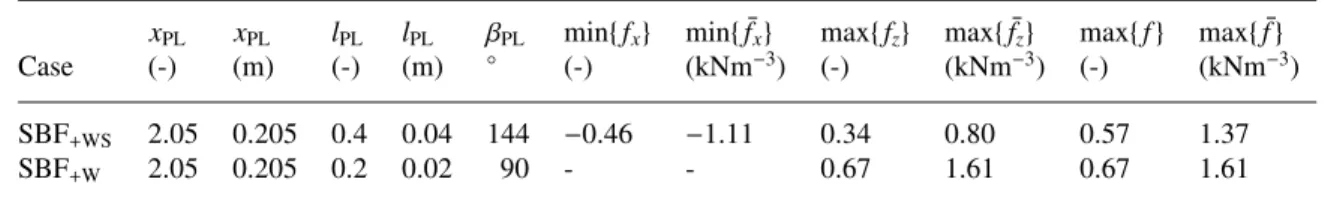
Table 1. Plasma-actuator characteristics for cases SBF+WSand SBF+W. Dimensioned values correspond toMa∞=0.04 experiment.
xPL xPL lPL lPL βPL min{fx} min{f¯x} max{fz} max{f¯z} max{f} max{f¯}
Case (-) (m) (-) (m) ◦ (-) (kNm−3) (-) (kNm−3) (-) (kNm−3) SBF+WS 2.05 0.205 0.4 0.04 144 −0.46 −1.11 0.34 0.80 0.57 1.37
SBF+W 2.05 0.205 0.2 0.02 90 - - 0.67 1.61 0.67 1.61
(not shown) indicated that the force should spread almost over the complete boundary layer but not extend beyond the boundary-layer thickness. Strong forcing close to the wall may result in s-shaped ˜ws,zm-profiles and amplification of
narrow-spaced CFV modes with high spanwise wavenumbers. Forcing outside the boundary layer is ineffective since the streamwise velocity profile does not become fuller near the wall and the crossflow velocity is not reduced.
The effect of the forcing on the mean flow is shown in figure 5(a). Note that the decrease in the shape factor (H12
=δ1/δ2,δ2- momentum loss thickness) and the maximum CF velocity starting atx≈3.2 for case REF is caused by
the high-amplitude CFVs. For both cases with actuation the modulus of the maximum crossflow velocity is reduced. The reduction decreases downstream but is of relevant size throughout the region of primary CF instability. For case SBF+WSa stronger decrease is found with a maximum reduction of about 45% at x=2.25 in comparison to about
30% for case SBF+W. However, in the vicinity of the actuators the shape factor increases for case SBF+WS, indicating
blocking of the flow which may give risk to local T-S instability. For case SBF+Wa decrease ofH12,s,zmis found. In
accordance with those findings the spanwise mean ˜us,zm-profile atx=2.0 (not shown) becomes slightly fuller in the near-wall region for case SBF+W, whereas for case SBF+WSthe streamwise velocity is decreased. Further downstream,
in consistency with the decrease ofH12,s,zm, also the ˜us,zm-profiles for case SBF+WSbecome fuller close to the wall.
To gain further inside into the effect of the plasma actuators on the stability properties of the flow, the resulting spanwise mean of the velocity fields from simulations without disturbance input were taken for LST calculations, see figure 5(b). Compared to the base flow the amplification rates of the most amplified steady CFV modes are reduced for both cases. The maximum n-factor ( −αidx, starting from neutral position for each mode) atx=4.3 is reduced
from 5.6 to 3.3 for case SBF+WS and to 4.4 for case SBF+W. The effect on the amplification of the unsteady CFV
modes withω=6 is similar and the reduction of the amplification rates is even slightly stronger (not shown). The downstream development of ˜usfor both cases is shown in figure 6. The forcing with two actuators per spanwise wavelength excites the mode (0,2) that is outside the primary-instability range. It is much larger in the beginning in case SBF+WS because the actuator axes lie approximately along the CFV axis direction, whereas in case SBF+W
z x (a) z x (b) z x z y
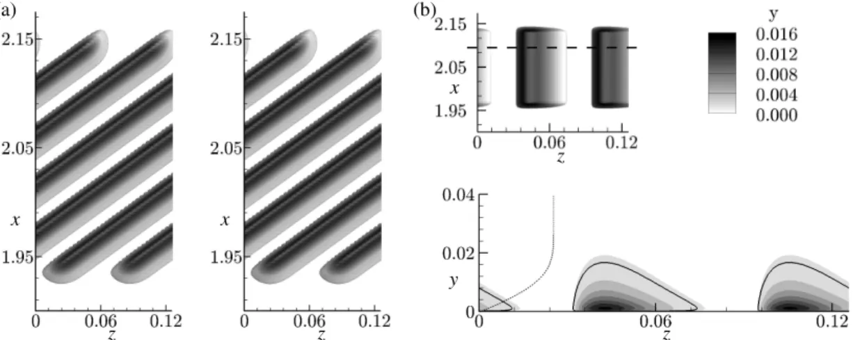
Fig. 4. (a) Body-force distribution for case SBF+WS. Left: 10%fx-isosurface (fx,10%=min{fx}/10=−0.046), right: 10%fz-isosurface (fz,10%=
max{fz}/10=0.034). The gray scale indicates the wall-normal distance y. (b) Body-force distribution for case SBF+W. Top: 10% isosurface (f10% = fz,10%=0.067); note the compression of thex-axis. The gray scale indicates the wall-normal distance y. Bottom: Crosscut along the horizontal
dashed line; the solid line denotes f10%. The force distribution is visualized by gray scale (levels 0.05 to 0.65, with increment 0.10) and the dotted
line shows theuB,s-profile of the undisturbed base flow atx=2.0.
(a) H12 , s , zm mi ny { ˜ ws, zm } ˜ ws H12,s x (b) γ x x γ
Fig. 5. (a) Downstream development of the shape factorH12,s,zm(full lines) and the maximum crossflow velocity miny{w˜s,zm}(dashed lines) for
case REF (no symbols), case SBF+WS(squares) and case SBF+W(circles). Values are based on the spanwise mean of the ˜usand ˜wsvelocity
components, respectively. (b) Amplification rates−αiof unstable steady CFV modes (LST). Top: case SBF+WS, bottom: case SBF+W. Values for
cases SBF+WSand SBF+Win gray scale, lines show base-flow data (levels 0.00 to−2.25, with increment 0.25).
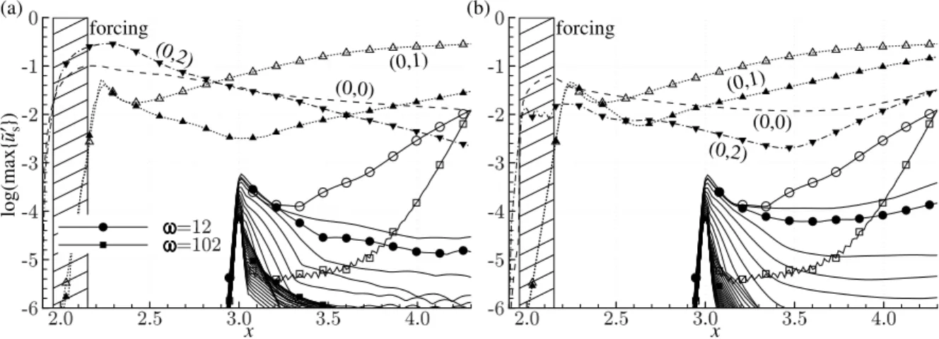
destructive interference occurs. The two-dimensional mean-flow distortion (0,0) reaches large amplitudes while, in accordance with the decreased CF velocity and the resulting stabilization of the base flow, the amplitude of the excited fundamental mode (0,1) decreases in comparison to the reference case, with a stronger decrease for case SBF+WS. For
this case the growth of all secondary-instability modes is eliminated completely within the integration domain. For case SBF+W secondary growth is also significantly reduced and amplification is found for the low-frequency modes
ω=6 andω=12 only. However, bear in mind that for case SBF+Wthe forcing amplitude can be further increased to
enhance the positive effect.
To check whether the suppression of the fundamental mode (0,1) is mainly caused by the mean-flow distortion (0,0) or by the three-dimensional effect of the mode (0,2) two manipulated simulations were performed (not shown). Artificial base flows were composed by superimposing the original base flow with the mode (0,0) extracted from case SBF+WS and case SBF+W, respectively. The excited disturbances were the same as for the original cases. For
(a) log(max { ˜ us } ) (0,1) (0,0) (0,2) forcing x (b) (0,1) (0,0) (0,2) forcing x
Fig. 6. Downstream development of modal ˜u
s,(h,k)- and ˜us,(h)-amplitudes for (a) case SBF+WSand (b) case SBF+Wfrom Fourier analysis in time
(maximum overyoryandz, 0≤ω≤180,Δω=6). The dashed line denotes the mean-flow distortion (0,0), the dotted lines with triangle the mode (0,1) and the dash-dotted lines with gradients the mode (0,2). Lines marked with open symbols show corresponding reference data from case REF.
Table 2. Plasma-actuator characteristics for cases CNL+WSand CNL−WS. The dimensioned force corresponds to theMa∞=0.04 experiment. xPL lPL zPL βPL min/max{fx} min/max{fz} max{f} max{f¯}
Case (-) (-) (-) ◦ (-) (-) (-) (kNm−3)
CNL+WS 3.40 0.25 0.040 135 −0.59 0.59 0.84 2.01
CNL−WS 3.35 0.25 −0.005 −45 0.59 −0.59 0.84 2.01
case SBF+WSit is found that, with respect to the growth attenuation of the mode (0,1), the (0,0) part alone is nearly
as efficient as the total effect of the forcing; however, the amplitude of the mode (0,1) is higher. This is due to the large amplitude of the mode (0,2) in the original case SBF+WSwhich locally dominates and hinders the growth of the
mode (0,1). Hence, the suppression of mode (0,1) is caused by a combination of both the two-dimensional mean-flow distortion and the three-dimensional effect of the mode (0,2). For case SBF+Wthe amplitude of the mode (0,2) is in the
order of≈1% only. Thus, the resulting three-dimensional part of the flow-field deformation is small. Consequently, the amplitude curves of the mode (0,1) for the original and the manipulated case nearly coincide throughout the whole integration domain, showing the importance of the two-dimensional mean-flow distortion for case SBF+W.
5. Control of the nonlinear disturbance state
In a first attempt to minimize the actuation energy, one actuator per fundamental wavelength is positioned at a selected spanwise position to alter the large-amplitude CFVs and the associated flow field, cf. the pinpoint suction concept7,9. In this first study it is found that forcing either against the CF or in direction of the CF are efficient. For
forcing against the CF, in the following denoted as case CNL+WS, the spanwise position of the actuator should be such
that the maximum of the force lies directly underneath the oncoming CFV, which herein after is referred to as CFV
A, cf. figure 7(a). For forcing in CF direction, denoted as case CNL−WS, the maximum force should be positioned
next to the updraft side ofA, cf. figure 7(b). For both cases the optimal wall-normal force distribution is such that the force extends almost up to the center ofA. Hence, compared to stabilization of the base flow, the optimal force distribution is flatter. The most important plasma-actuator characteristics applied in the two cases are given in table 2. Whereas the forcing direction and the position in thex−zplane differ, the same force distribution is used for both set-ups. Although the maximum force is slightly larger than for cases SBF+WSand SBF+W, the integral force is lower
(a) xr zr f us −ws A zr y B f A (b) xr zr f A zr y f A B
Fig. 7. Basic control set-up. Left: Steady CFVs to be controlled (λ2=−6, bright) of case REF and body-force for (a) case CNL+WSand (b) case
CNL−WS(10% isosurface, f10%=0.084, dark). A rotated reference system withx0 =2.5,z0=−0.04 andΦr=45◦is used. Right: Crosscut
along the dashed line atxr=1.33. The force distribution is visualized by gray scale (levels 0.05 to 0.75, with increment 0.10). The lines show
λ2-isoncotours of case REF (levels−12 to−2, with increment 2).
The effect of the forcing on the CFVs for case CNL+WSis shown in figure 8(a). In this case, the wall-parallel
velocity induced by the forcing seems to weaken the rotational fluid motion of CFV A close to the wall and, in addition, the induced negative wall-normal velocity hampers the vortical motion at the updraft side ofA. As a result of the nonlinear interaction of the CFVAand the vortices generated by the actuator, see figure 8(b), two counter-rotating vortices are generated near the actuator edges,CandD(figure 8(a)).Cinduces a movement of the oncoming CFVA
to the left where it dies out soon. AlsoCdisappears soon downstream the actuator. Finally, the new CFVDgrows in amplitude further downstream. Note that the vortical structures are similar to those arising with pinpoint suction when three successive suction holes are employed, see figure 10 in9, case 3-H. For case CNL
−WS, the induced wall-parallel
velocity is presumed to promote the rotational fluid motion ofAclose to the wall. However, a new clockwise turning vortexEdevelops next toA, see figure 8(c). In combination with the induced negative wall-normal velocity it hinders the vortical motion ofAover some distance before it dies out again. Consequently, the strength ofAis reduced. However, in contrast to case CNL+WSApersists and is not replaced by a new CFV.
The downstream development of ˜usfor cases CNL+WS and CNL−WS is shown in figure 9. Downstream of the
forcing the amplitude of the excited fundamental mode (0,1) decreases for both cases compared to the reference case, with a slightly stronger decrease for case CNL−WS. In accordance with the formation of the vorticesCandE, the
mode (0,2) grows in the vicinity of the actuators and decreases again once the vortices have died out. The growth of secondary-instability modes is reduced for all modes.
Unfortunately, both forcing directions are sensitive with respect to the spanwise position of the actuators, and ill-chosen positioning may enhance transition to turbulence. When forcing against the CF, shifting the actuator towards the vortexByields promoting the vortical motion of this vortex, which in turn increases the strength ofA. Shifting it towards the downdraft side ofA, the induced negative wall-normal velocity directly promotes the vortical motion ofA. For forcing in direction of the CF, positioning the actuator such that the maximum force lies underneath or at the downdraft side ofAdirectly results in increased strength of the CFV. However, in taking up the mechanisms of the pinpoint suction concept where a fundamental favourable action of the mean suction effect exists independent of the spanwise position of the holes, it might be useful to tilt the actuators by about 90◦. Thus, an acceleration of the mean flow reduces the basic crossflow, and the induced downdraft of fluid above the actuator may give the desired ’pinpoint’ vortex-weakening action. Moreover, several actuator rows are conceivable.
6. Conclusions
Using DNS two methods have been investigated applying plasma actuators to control the crossflow-vortex-induced laminar breakdown in a three-dimensional swept-wing-type boundary-layer flow. For the first method, the objective has been to weaken the primary CF instability by reducing the CF velocity of the quasi two-dimensional base flow. Applying two actuators within the spanwise wavelength of the most amplified CFV mode, it is found that forcing
(a) xr zr A D zr y A B C D (b) xr zr zr y (c) xr zr A E A zr y A E
Fig. 8. Like figure 7 but with activated body force: (a) case CNL+WS, (b) case CNL+WSwithout oncoming CFV and (c) case CNL−WS.
(a) log(max { ˜ us } ) (0,1) (0,2) forcing x (b) (0,1) (0,2) forcing x
Fig. 9. Downstream development of modal ˜us,(h,k)- and ˜us,(h)-amplitudes for (a) case CNL+WSand (b) case CNL−WSfrom Fourier analysis in time
(maximum overyoryandz, 0≤ω≤180,Δω=6). The dotted lines with triangle denote the mode (0,1) and the dash-dotted lines with gradients the mode (0,2). Lines marked with open symbols show corresponding reference data from case REF.
either in spanwise direction or against the CF is most effective. The force distribution in wall-normal direction should be such that the force spreads almost over the complete boundary layer. Strong localized forcing close to the wall may causeS-shapedws-profiles and should be avoided. For both forcing directions the maximum CF velocity is reduced, showing a stronger decrease for forcing against the CF. However, blocking of the flow is found here in the vicinity of the actuators which may give rise to local T-S instability. LST investigations confirm that the forcing reduces the amplification rates of both steady and unsteady CFV modes for both cases. In accordance, the amplitudes of the CFV modes in the DNS decrease and the growth of all secondary-instability modes is significantly attenuated. Manipulated simulations using modified artificial base flows reveal that for forcing against the CF the attenuation of the mode (0,1) is caused by a combination of the two-dimensional mean-flow distortion and the three-dimensional part of the flow-field deformation, whereas for forcing in spanwise direction the three-dimensional deformation is of minor importance.
For the second method the actuators have been used to control the three-dimensional nonlinear disturbance state with large-amplitude CFVs, similar to the pinpoint suction concept. One actuator per fundamental wavelength is positioned at a selected spanwise position to alter the vortices and the associated flow field. Forcing either against the CF or in direction of the CF can be efficient. The wall-normal range of the force should not extend beyond the center of the oncoming CFV. For forcing against the CF, the spanwise position of the actuator should be such that the maximum of the force lies directly underneath the oncoming CFV. The wall-parallel velocity induced by the forcing weakens the rotational fluid motion close to the wall and, in addition, the induced negative wall-normal velocity ham-pers the vortical motion at the updraft side of the CFV. For forcing in CF direction, the actuator should be positioned next to the updraft side of the CFV. The induced wall-parallel velocity promotes the rotational fluid motion caused by the CFV, resulting in the formation of a new, additional CFV which hinders the vortical motion of the original CFV over some distance downstream of the forcing. Upon lowering the CFV amplitude, in either case the growth of all secondary-instability modes is attenuated, delaying transition to turbulence. Note that with a plasma actuator, a downdraft motion to the wall is induced independent of the direction in the wall-parallel plane. However, both forcing directions are sensitive with respect to the spanwise position of the actuators and ill-chosen positioning may enhance transition to turbulence.
The financial support by the German Ministry for Economic Affairs and Energy through the LuFo IV-4 project ’AKSA’ and the computational resources provided by the HPC Center Stuttgart (HLRS) are gratefully acknowledged.
References
1. Saric, W.S., Reed, H.L., White, E.B.. Stability and transition of three-dimensional boundary layers.Annu Rev Fluid Mech2003;35:413–40. 2. Wassermann, P., Kloker, M.. Transition mechanisms induced by travelling crossflow vortices in a three-dimensional boundary layer.J Fluid
Mech2003;483:67–89.
3. Bonfigli, G., Kloker, M.. Secondary instability of crossflow vortices: validation of the stability theory by direct numerical simulation. J Fluid Mech2007;583:229–272.
4. Joslin, R.D.. Overview of laminar flow control. Tech. Rep. TP-1998-208705; NASA, Langley Research Center, Hampton, Virginia; 1998. 5. Saric, W.S., Carrillo, R., Reibert, M.S.. Leading-edge roughness as a transition control mechanism. In:36th Aerospace Sciences Meeting
&Exhibit. 1998, AIAA Paper 98-0781.
6. Wassermann, P., Kloker, M.J.. Mechanisms and passive control of crossflow-vortex-induced transition in a three-dimensional boundary layer.J Fluid Mech2002;456:49–84.
7. Kloker, M.J.. Advanced laminar flow control on a swept wing - useful crossflow vortices and suction. In:38th Fluid Dynamics Conference and Exhibit. 2008, AIAA Paper 2008-3835.
8. Messing, R., Kloker, M.J.. Investigation of suction for laminar flow control of three-dimensional boundary layers. J Fluid Mech2010; 658:117–147.
9. Friederich, T., Kloker, M.J.. Control of the secondary crossflow instability using localized suction.J Fluid Mech2012;706:470–495. 10. Grundmann, S., Tropea, C.. Experimental damping of boundary-layer oscillations using DBD plasma actuators.Int J Heat Fluid Fl2009;
30:394–402.
11. Hanson, R.E., Bade, K.M., Belson, B.A., Lavoie, P., Naguib, A.M., Rowley, C.W.. Feedback control of slowly-varying transient growth by an array of plasma actuators.Phys Fluids2014;.
12. Duchmann, A., Simon, B., Tropea, C., Grundmann, S.. Dielectric barrier discharge plasma actuators for in-flight transition delay.AIAA J 2014;52:358–367.
13. Kurz, A., Simon, B., Tropea, C., Grundmann, S.. Active wave cancellation using plasma acutators in flight. In: 52 AIAA Aerospace Sciences Meeting. 2014, .
14. Riherd, M., Roy, S.. Damping Tollmien-Schlichting waves in a boundary layer using plasma actuators. J Phys D: Appl Phys2013; 46:485203.
15. Kotsonis, M., Giepmann, R., Hulshoff, S., Veldhuis, L.. Numerical study of the control of Tollmien-Schlichting waves using plasma actuators.AIAA J2013;51:2353–2364.
16. Schuele, C.Y., Corke, T.C., Matlis, E.. Control of stationary cross-flow modes in a Mach 3.5 boundary layer using patterned passive and active roughness.J Fluid Mech2013;718:5–38.
17. Babucke, A., Linn, J., Kloker, M.J., Rist, U.. Direct numerical simulation of shear flow phenomena on parallel vector computers. In: B¨onisch, T., Benkert, K., Furui, T., Seo, Y., Bez, W., editors.High Performance Computing on Vector Systems 2005; Proc. High Performance Computing Center Stuttgart (HLRS). Springer; 2006, p. 229–247.
18. Kurz, H.B.E., Kloker, M.J.. Receptivity of a swept-wing boundary layer to micron-sized discrete roughness elements. J Fluid Mech2014; 755:62–82.
19. Maden, I., Maduta, R., Kriegseis, J., Jakirlic, S., Schwarz, C., Grundmann, S., et al. Experimental and computational study of the flow induced by a plasma actuator.Int J Heat Fluid Fl2013;41:80–89.
20. Bonfigli, G.. Numerical simulation of transition and early turbulence in a 3-d boundary layer perturbed by superposed stationary and travelling crossflow vortices.Ph.D. thesis; Institut f¨ur Aerodynamik und Gasdynamik, Universit¨at Stuttgart; 2006.