Mark P. Wernet
Glenn Research Center, Cleveland, Ohio
Benjamin R. Stiegemeier
Axiometix, Shawnee Mission, Kansas
Application of Background Oriented Schlieren for
Altitude Testing of Rocket Engines
NASA/TM—2017-219578
NASA STI Program . . . in Profi le
Since its founding, NASA has been dedicated to the advancement of aeronautics and space science. The NASA Scientifi c and Technical Information (STI) Program plays a key part in helping NASA maintain this important role.
The NASA STI Program operates under the auspices of the Agency Chief Information Offi cer. It collects, organizes, provides for archiving, and disseminates NASA’s STI. The NASA STI Program provides access to the NASA Technical Report Server—Registered (NTRS Reg) and NASA Technical Report Server— Public (NTRS) thus providing one of the largest collections of aeronautical and space science STI in the world. Results are published in both non-NASA channels and by NASA in the NASA STI Report Series, which includes the following report types: • TECHNICAL PUBLICATION. Reports of
completed research or a major signifi cant phase of research that present the results of NASA programs and include extensive data or theoretical analysis. Includes compilations of signifi cant scientifi c and technical data and information deemed to be of continuing reference value. NASA counter-part of peer-reviewed formal professional papers, but has less stringent limitations on manuscript length and extent of graphic presentations.
• TECHNICAL MEMORANDUM. Scientifi c and technical fi ndings that are preliminary or of specialized interest, e.g., “quick-release” reports, working papers, and bibliographies that contain minimal annotation. Does not contain extensive analysis.
• CONTRACTOR REPORT. Scientifi c and technical fi ndings by NASA-sponsored contractors and grantees.
• CONFERENCE PUBLICATION. Collected papers from scientifi c and technical
conferences, symposia, seminars, or other meetings sponsored or co-sponsored by NASA. • SPECIAL PUBLICATION. Scientifi c,
technical, or historical information from NASA programs, projects, and missions, often concerned with subjects having substantial public interest.
• TECHNICAL TRANSLATION. English-language translations of foreign scientifi c and technical material pertinent to NASA’s mission. For more information about the NASA STI
program, see the following:
• Access the NASA STI program home page at http://www.sti.nasa.gov
• E-mail your question to help@sti.nasa.gov • Fax your question to the NASA STI
Information Desk at 757-864-6500
• Telephone the NASA STI Information Desk at 757-864-9658
• Write to:
NASA STI Program Mail Stop 148
NASA Langley Research Center Hampton, VA 23681-2199
Mark P. Wernet
Glenn Research Center, Cleveland, Ohio
Benjamin R. Stiegemeier
Axiometix, Shawnee Mission, Kansas
Application of Background Oriented Schlieren for
Altitude Testing of Rocket Engines
NASA/TM—2017-219578
National Aeronautics and
Space Administration
Glenn Research Center
Cleveland, Ohio 44135
Available from
Trade names and trademarks are used in this report for identifi cation only. Their usage does not constitute an offi cial endorsement,
either expressed or implied, by the National Aeronautics and Space Administration.
Level of Review: This material has been technically reviewed by technical management.
NASA STI Program Mail Stop 148
NASA Langley Research Center Hampton, VA 23681-2199
National Technical Information Service 5285 Port Royal Road Springfi eld, VA 22161 703-605-6000 This report is available in electronic form at http://www.sti.nasa.gov/ and http://ntrs.nasa.gov/
This work was sponsored by the Transformative Aeronautics Concepts Program.
Application of Background Oriented Schlieren for
Altitude Testing of Rocket Engines
Mark P. Wernet
National Aeronautics and Space Administration Glenn Research Center
Cleveland, Ohio 44135 Benjamin R. Stiegemeier
Axiometix
Shawnee Mission, Kansas 66202
Summary
A series of experiments were performed to determine the feasibility of using the Background
Oriented Schlieren (BOS) flow visualization technique to image a simulated, small, rocket engine, plume under altitude test conditions. Testing was performed at the NASA Glenn Research Center’s Altitude Combustion Stand (ACS) using nitrogen as the exhaust gas simulant. Standard flow visualization and/or conventional Schlieren systems cannot be implemented in the ACS due to the limited optical access to the facility test capsule. In order to overcome these obstacles, all of the hardware required to implement the BOS system were located inside the vacuum chamber. During the test series 28 runs were performed using three different nozzle configurations with pressures in the test capsule maintained at approximately 0.3 psia. No problems were encountered during the test series resulting from the optical hardware being located in the test capsule and images of the density field in the rocket nozzle plume were acquired. The test campaign demonstrated the applicability of using the BOS technique to measure the shock structure emanating from small, rocket engines during altitude testing.
Introduction
The Background Oriented Schlieren technique is a widely used tool for studying the density fields in complex flow fields. Typically, the flows are supersonic, where the flow features of interest are the locations of the shocks in the flow. The BOS technique is similar to classic knife edge Schlieren in that the property of the flow that is measured is the derivative of the density. Classic Schlieren typically requires large diameter mirrors to collimate the illumination light and also the use of high quality optical windows on the walls of the wind tunnel (Ref. 1). However, unlike classic Schlieren, BOS uses a relatively simple optical setup and has much less demanding requirements on the quality of the optical glass long the imaged path (Ref. 2). A second distinction of BOS is that it provides both the x- and y-components of the derivative of the density field whereas classic knife edge Schlieren only provides a single component of the density field rate-of-change. The BOS technique employs a camera to image a random dot or speckled background pattern. The speckled background must be illuminated in order for the camera to record images of the speckle pattern. Before the flow is turned on, a reference, or
“wind-off” image is acquired by the camera. Next, a nonuniform density field is placed between or the flow is turned on between the camera and the speckled background. The density disturbances long the imaged path yield distortions in the image of the speckled background image. The acquired distorted images are then cross-correlation processed against the reference image using standard Particle Image Velocimetry (PIV) processing techniques to measure the density gradient in both the x- and y-directions. Improvements in the BOS processing have continued and the current state of the art uses a Least Squares Matching algorithm to measure the displacements (distortion) between the reference image and the “wind on” images (Ref. 3).
NASA/TM—2017-219578 2
BOS has been used in both enclosed wind tunnel flows and in external flows utilizing full scale rotorcraft and aircraft. In each of these applications, innovative backgrounds are used, such as leafy trees or the desert floor or even the surface of the Sun (Refs. 4 and 5). The main requirement is that the reference image is unchanged during the duration of the measurement. For most indoor/wind tunnel applications of BOS, manmade speckle backgrounds are typically employed. Usually a light speckle pattern is sprayed on a dark background. The size and density of the speckle pattern affects the sensitivity of the technique. The optimal size of the imaged “speckle” onto the CCD sensor should nominally span 2 to 3 pixels (Ref. 2). Hence a wide range of speckle patterns must typically be generated for each new experiment/field-of-view. Additionally, these speckle patterns must be sufficiently illuminated so that the camera can detect the speckle pattern with high contrast. Obtaining uniform illumination across the speckled background target and avoiding glare spots is a challenging task. Limited optical access ports in wind tunnel facilities can exacerbate the issue.
In this work an innovative approach for generating the background speckle patterns was employed. The speckle patterns required for the BOS measurement were displayed on a high definition 4K
resolution computer monitor. Use of the 4K HD monitor to display the speckle patterns has three distinct advantages: the speckle patterns can be generated on the computer and displayed directly on the monitor without having to physically construct the speckle pattern, the scale of the speckle pattern can be readily changed to optimize the BOS system performance and finally, the speckle pattern is self-illuminating, which greatly simplifies implementing the technique in confined environments. The self-illuminated background provides an additional advantage in the aperture setting of the camera. Increasing the f/number on the camera lens minimizes the geometric blur in the acquired BOS image data (Ref. 2). Typically, operating a BOS system at high f/number is a challenge since it depends on being able to brightly illuminate the background. The self-illuminated background provides sufficient light so that the camera lens can be set to a high f/number, thereby enabling a more optimal configuration of the optical system.
The self-illuminated background was an essential element in the installation of the BOS system in the Altitude Combustion Chamber (ACS) at NASA GRC. Due to the lack of sufficient optical access, the entire BOS system was installed inside the vacuum capsule of the ACS. Measurements of the shock patterns in rocket jet plumes exhausting into a near vacuum environment were recorded for the first time ever in the ACS using the BOS system.
Facility and Hardware Description
Testing for this experimental program was conducted in the Altitude Combustion Stand, ACS, at the NASA Glenn Research Center. The facility was designed to conduct altitude testing of rocket engines up to 2000 lbf thrust level with a variety of propellant combinations. Major components of the facility include a test capsule, diffuser, spray capsule, ejectors and pressure vessels. For this series of cold flow tests the facility diffuser and spray capsule were not used. During testing, active pumping of the test capsule was performed by the facility’s nitrogen gas powered ejector train. The ejector train used during this investigation does not deliver the facility’s highest pumping rates, but was sufficient to evacuate the nozzle nitrogen gas flow rates used in this experimental program. The test hardware was mounted to the thrust stand at the bulkhead end of the 8-ft-diameter by 14-ft-long cylindrical test capsule. Nitrogen gas was supplied to the test articles using the existing facility gaseous hydrogen system which enters the test capsule through feed-throughs in the bulkhead end of the test capsule. More information regarding the test facility and its capabilities can be found in Reference 6.
A simplified process and instrumentation diagram (P&ID) for the test set-up is shown in Figure 1. Nitrogen gas was supplied to the facility gaseous hydrogen system from a standard 2400 psi tuber located in the facility propellant storage area. Eight pressure transducers and six thermocouples were used to measure the nitrogen flow through the feed system up to the main valve for this set of experiments. Downstream of the main valve a 0.125-in. throat diameter sub-sonic venturi was used to measure the nitrogen gas flow rate. Two pressure transducers and two thermocouples, one set upstream and one set
Figure 1.—Simplified process and instrumentation diagram for the Background Oriented Schlieren experiments. downstream, along with one differential pressure transducer were used to calculate the flow rate through the venturi. One final pressure transducer was located just upstream of the nozzle to monitor the inlet pressure to the test hardware. Data was collected at 1000 Hz for all instruments used in this test series by the facility’s National Instruments based data system while control and timing of the facility valves during testing was accomplished using the facility control system which is composed of programmable logic controllers (PLC). Along with the instruments shown in Figure 1, 14 additional facility instruments were recorded which were used to monitor ejector train and test capsule pressures. After completing a run, the data set was post processed using a MATLAB (The Mathworks, Inc., Natick, MA) based data reduction program that incorporated the National Institute of Standard’s (NIST) Refprop to determine fluid thermodynamic properties.
Three different nozzle configurations were used during this test program. The first was a repurposed sonic venturi that was used for initial check out runs to verify the BOS hardware operation. The venturi was terminated with a small section of straight tube used to generate a cylindrical, supersonic jet. The second phase of testing was performed with a small, copper, heat sink, rocket nozzle that had been used in previous hot fire test programs. The copper nozzle had a throat diameter of 0.097 in., a half angle of 15° and a supersonic area ratio of approximately 22.5. The third configuration was another sonic venturi which had a throat diameter of 0.059 in. The size of the third venturi throat was consistent with nozzles in engines that produce about 0.22 to 1.1 lbf (1 to 5 newtons) of thrust and would be used in micro and cube satellite propulsion systems.
The design of a BOS experiment must be optimized for the desired field-of-view (FOV) and
sensitivity of the measurements, which are of course conflicting requirements. The camera used for these studies was a Basler 1920×1080 pixel camera with 8.3×10⁻⁵ (2.2 µm) pixels. For this series of tests, three
different BOS configurations were employed, each with a different FOV, and hence a different
sensitivity. Two of the configurations used a 24 in. diagonal 4K monitor to achieve 3×6 in. and 10×16 in. FOVs and the third configuration used a 27 in. monitor for a 13×24 in. FOV. The smallest FOV was achieved using a 0.669 in. (17 mm) focal length lens, while the 10×16 in. FOV was achieved using a 0.472 in. (12 mm) lens. The largest FOV was obtained using a 0.33 in. (8.5 mm) lens. For all
configurations the monitor was located 36 in. from the test article and the cameras were positioned 24 in. from the test article. These distances were constrained by the 4 ft inside radius of the capsule.
PT PT TC Test Capsule Bulkhead PT DP TC PT PT TC TC PT PT PT PT TC TC TC TC TC TC PT PT 2400 psi GN2 Tuber PT PT Sub-Sonic Venturi Nozzle Main Valve
NASA/TM—2017-219578 4
Figure 2.—BOS installation in ACS, the camera views the background image on the monitor through the nitrogen gas simulated rocket exhaust plume. In this photo the capsule is retracted downstream in order to provide access to the BOS hardware.
Due to the lack of optical access ports, both the BOS camera and the self-illuminated background were rigidly mounted inside the vacuum chamber. The camera was equipped with anodized heat sinks to aid in radiating heat away from the camera in the near vacuum environment. The 4K monitor was turned off between runs to minimize heating of the monitor and the chamber. Figure 2 shows the experimental test set up including the copper heat sink nozzle, 4K monitor and camera used to capture the flow visualization images.
Results and Discussion
Twenty-eight experimental runs were performed during this test program. The supply pressure to the test hardware, measured at the final pressure transducer in the feed system, the test capsule vacuum pressure, the run duration and nitrogen flow rate for all runs are summarized in Table 1. All of the runs in the test program were conducted for 10 sec, except for run 765 which lasted for 20 sec in order to verify that the ejector train pumping capacity was sufficient to keep the test capsule pressure stable during an extended run. The 10 sec run time was long enough to reach steady state conditions in the nozzle gaseous nitrogen flow and feed system pressures. Runs 753 to 770, shaded in light gray in Table 1, were check out runs that utilized the repurposed first venturi as a nozzle to verify the operation of the BOS hardware. After the completion of run 770, the copper heat sink nozzle was installed for the second block of tests. These tests, runs 775 to 785 (unshaded in Table 1) were generally higher pressure tests and were
conducted to give a breadth of nozzle plumes for the BOS hardware to image. The final set of tests, runs 787 to 795 which are shaded dark gray in Table 1, were lower pressure tests conducted with the second sonic venturi nozzle. These tests are more consistent with the expected chamber pressures of small reaction control engines. The flow rates generated in these latter tests would roughly correspond to micro and cube sat engines that would deliver approximately 0.22 to 1.1 lbf (1 to 5 newtons) of thrust.
4K HD Monitor
Nozzle Assembly Camera
TABLE 1.—SUMMARY OF TEST CONDITIONS Run number,
~ Supply pressure, psia Vacuum pressure, psia Flow rate, lbm/sec Duration, sec
753 402 0.30 0.081 10 754 1001 0.28 0.205 10 765 988 0.25 0.202 20 766 793 0.25 0.161 10 767 598 0.25 0.121 10 768 403 0.26 0.081 10 769 206 0.26 0.041 10 770 110 0.27 0.022 10 775 1186 0.28 0.200 10 776 990 0.28 0.167 10 777 795 0.28 0.133 10 778 598 0.27 0.100 10 779 403 0.28 0.067 10 780 209 0.28 0.035 10 781 113 0.28 0.019 10 782 306 0.29 0.051 10 783 502 0.29 0.083 10 784 714 0.30 0.120 10 785 893 0.30 0.150 10 787 112 0.29 0.007 10 788 110 0.30 0.007 10 789 135 0.29 0.009 10 790 159 0.30 0.010 10 791 186 0.30 0.012 10 792 209 0.31 0.013 10 793 233 0.31 0.015 10 794 256 0.32 0.016 10 795 184 0.32 0.012 10
After the completion of a day of test runs, the BOS data were post-processed by performing a cross-correlation operation analogous to the procedure used to process Particle Image Velocimetry (PIV) data. The LaVision StrainMaster software package was used to process all of the BOS data acquired during the ACS test program. The StrainMaster software uses the Least Squares Matching approach for measuring the speckle pattern displacements generated on the computer screen. As BOS is a path integrated technique, the sum of all of the density variations in the flow across the full width of the passage cause localized distortions of the speckle pattern, which are measured as displacements of the speckle pattern relative to the reference image. Dividing the images up into small interrogation regions and processing the interrogation regions yields the local x-component and y-component of the variations in density across the integrated path of the flow. For the highest spatial resolution images (smallest FOV), a subregion size of 7×7 pixels on 3×3 pixel centers was used to process the images. For the lower
resolution, coarser quality images, larger subregions of 15×15 pixels on 7×7 pixel centers were used. Image sequences of 100 images were acquired and processed. The processed displacement maps were then used to compute the ensemble averaged displacement fields. The measurement error in the BOS technique is nominally reported as 2 to 3 percent of full scale (Ref. 2).
Data were acquired in the ACS chamber for nominal tank pressures of 0.3 psia. As described previously, during the acquisition the nominal pressure in the tank remains at 0.3 psia as the ejector train continues pulling down the tank pressure during the run. A sonic venturi with a 0.105 in. diameter nozzle was operated at two plenum pressures: 1000 psi (run 754), corresponding to a mass flow of 0.205 lbm/sec and 400 psi (run 753), which corresponds to a mass flow of 0.081 lbm/sec. The BOS system was
configured for a 3×6 in. field of view, yielding measured displacements up to 3.5 pixels in the strongest shocks at the nozzle exit. A color contour plot of the ensemble average of 100 processed BOS images is shown in Figure 3. The color contours in the figure correspond to the ensemble averaged displacement
NASA/TM—2017-219578 6
magnitude—where the x- and y-components of the displacement are used to compute the displacement magnitude. The underexpanded jet plume and the associated expansion fans are visible at the nozzle exit as the plume expands as the exit pressure is reduced to match the test capsule ambient pressure. At a plenum pressure of 400 psi, again 100 BOS images are processed and ensemble averaged as shown in Figure 4. The maximum measured displacements due to the density gradients are approximately
1.5 pixels. Here, the jet plume is much shorter and the diameter is nearly half the diameter of the 1000 psi condition. The inner plume structure is again observed but now the fine scale structure is preserved for a longer distance downstream.
Figure 3.—Color contours of the average magnitude of the displacements due to the density gradients for the 0.105 in. diameter nozzle at a plenum pressure of 1000 psi.
Figure 4.—Color contours of the average magnitude of the displacements due to the density gradients for the 0.105 in. diameter nozzle at a plenum pressure of 400 psi.
The magnitude of the displacements measured using the BOS technique are defined as the product of the strength of the density gradient times the sensitivity (i.e., configuration) of the optical system (Ref. 2). For the 1000 and 400 psi nozzle cases, the optical system configuration is the same, hence the difference in the measured displacements is due only to the strength of the density gradients in the flow. At over twice the pressure ratio, the measured displacements are nearly double.
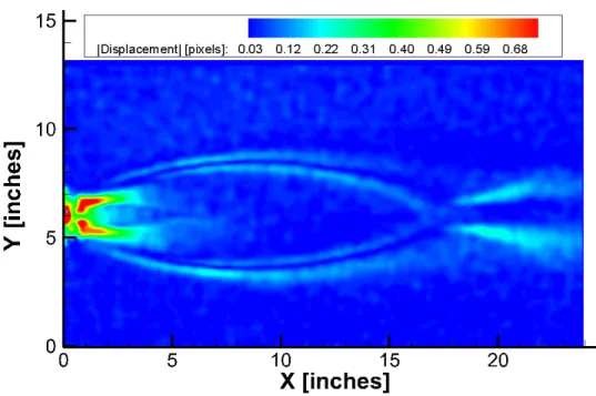
For the largest field of view case (13×24 in.), the same 1000 psi nozzle flow (run 765) yielded measureable displacements of 1 pixel, approximately 30 percent smaller than the displacements achieved at the smaller field-of-view, as observed in Figure 5. With the larger FOV, the complete first expansion fan structure is captured. The fidelity of the fine plume structures are not resolved in the larger FOV configuration. Figure 5 illustrates the effect of the BOS optical system sensitivity on the measurements, where the measured displacements from the same magnitude of density gradients in the 1000 psi nozzle flow has dropped by more than the ratio of the size of the field-of-view.
The 24 in. monitor was also used in a larger FOV (10×16 in.) configuration for the copper nozzle block tests. A sample case for the plenum pressure of 400 psi (run 779) is shown in Figure 6. The bolts on the end face of the nozzle block are evident in the processed displacement map. With the larger FOV more of the plume structure is captured. Again, by only changing the camera lens to increase the FOV, the sensitivity of the BOS system is decreased as evidenced by the coarser quality displacement map.
The small BOS FOV configuration (3×6 in.) was then used to measure a 0.059 in. diameter nozzle at a pressure of 135 psi (run 789) and a mass flow of 0.009 lbm/sec. Using the most sensitive BOS
configuration, the plume structure is still discernable even for this extremely low mass flow case, as shown in Figure 7.
It should also be noted that there was some discernable distortion around the perimeter of the 27 in. diagonal monitor between the ambient and vacuum condition. However, the effect was mitigated using the vacuum reference images. The smaller 24 in. diagonal monitor did not exhibit any indication of distortion between ambient and vacuum conditions. Neither monitor overheated during the testing. A monitor exhibiting minimal distortion in the vacuum environment is more desirable.
Figure 5.—Color contours of the average magnitude of the displacements due to the density gradients for the 0.105 in. nozzle at a plenum pressure of 1000 psi at the largest 13×24 in. FOV.
NASA/TM—2017-219578 8
Figure 6.—Color contours of the average magnitude of the displacements due to the density gradients for the 0.097 in. diameter nozzle at a plenum pressure of 400 psi.
Figure 7.—Color contours of the average magnitude of the displacements due to the density gradients for the 0.059 in. diameter nozzle at a plenum pressure of 135 psi.
Figure 8.—3D representation of the reconstructed BOS density field for the 1000 psi case shown in Figure 3.
The BOS technique provides both components of the derivative of the density field across the integrated path of the measurement. These two components can be integrated across both dimensions to reconstruct a representation of the original density field (Ref. 7). The reconstructions performed here are in arbitrary units. Proper calibration of the density field using local measurements of the density can possibly be used to reconstruct the density field into physical units. An example of the reconstructed density field is shown in Figure 8, where the 1000 psi nozzle at the smallest FOV case presented in Figure 3 has been integrated to yield the density field. The density field is shown as both a color contour map overlaid on a 3D surface representation of the density field. The extent of the finer scale inner plume structure is more readily observed in this reconstructed density map.
Conclusions
The Background Oriented Schlieren technique has been successfully implemented in the low pressure environment of the Altitude Combustion Chamber at NASA GRC. The ACS is a challenging facility not normally amenable to optical diagnostics since it has very limited optical access. A new approach to generating the background patterns in BOS was implemented in this installation, where a 4K HD monitor was used to provide a self-illuminated speckled background. Due to the limited optical access, the entire BOS system was installed inside the vacuum capsule in the ACS. A series of different nozzle designs across a range of pressures were tested using the BOS system, demonstrating that the BOS system is capable of detecting the expansion fans emanating from low mass flow nozzles at near vacuum conditions.
Implementing BOS in the ACS capsule is a trade-off between Field-of-View and resolution of the density field structures/details. The sensitivity of the BOS technique is affected by the distance between the test article and the speckle background pattern. The limited space inside the capsule restricts this distance for BOS applications in ACS. The best optical configuration was the 3×6 in. FOV system using the 0.669 in. (17 mm) focal length lens, where the fine plume structure in the jet plume were readily resolved. For a fixed camera to speckle pattern distance the only option for increasing the FOV was to reduce the focal length of the lens on the camera, however; using shorter focal lengths degraded the fidelity of the imaged speckle patterns, which reduced the resolution of the BOS data.
NASA/TM—2017-219578 10
Future implementations of BOS in the ACS could be improved by three methods. The first would require changing to a higher resolution camera sensor and a larger monitor, which would provide similar resolution and sensitivity as the small FOV system demonstrated here with an even larger FOV. The second would involve mounting the camera and the self-illuminating speckle background on the same side of the capsule and reflecting the optical path of the camera off of a mirror on the opposite side of the capsule. This approach increases the lever arm of the technique, but also complicates the setup. The third option would be to use multiple cameras/self-illuminated backgrounds to provide more axial coverage of the nozzle plumes, while still maintaining high resolution measurements.
The self-illuminated BOS system provided detailed maps of the nozzle plume structure in a simulated rocket engine using nitrogen as an exhaust gas simulate. The present demonstration was in a
noncombusting flow, however; we anticipate using the BOS technique in future combusting flow rocket nozzle studies in the ACS.
References
1. Settles, G.S., “Schlieren and Shadowgraph Techniques: Visualizing Phenomena in Transparent Media,” Springer-Verlag, ISBN 3-540-66155-7, 1949.
2. Raffel, M., “Background Oriented Schlieren (BOS) Techniques,” Exp. in Fluids 56:60, DOI 10.1007/s00348-015-1927-5, 2015.
3. Hild F., Roux S., “Digital image correlation: from displacement measurement to identification of elastic properties – a review”. Strain 42 (2):69–80, 2010.
4. Hargather M.J. and Settles G.S., “Natural-background-oriented schlieren imaging,” Exp. Fluids 48, pp. 59–68, 2010.
5. James T. Heineck, Daniel Banks, Edward T. Schairer, Edward A. Haering, and Paul Bean. “Background Oriented Schlieren (BOS) of a Supersonic Aircraft in Flight,” AIAA Flight Testing Conference, AIAA AVIATION Forum, (AIAA-2016-3356).
6. Meyer, M.L., Arrington, L.A., Kleinhenz, J.E. and Marshall, W.M., “Testing of a Liquid
Oxygen/Liquid Methane Reaction Control Thruster in a New Altitude Rocket Engine Test Facility,” NASA/TM—2012-217643.
7. Xie, W., Zhang, Y., Wang, C.C.L., Cheung, R. C.-K., “Surface-from-Gradients: An Approach Based on Discrete Geometry Processing,” The IEEE Conference on Computer Vision and Pattern