Bibek Shrestha
Fire Detection Using Image
Processing
Metropolia University of Applied Sciences Bachelor of Engineering
Electronics Bachelor’s Thesis 02 February 2020
Abstract Author Title Number of Pages Date Bibek Shrestha
Fire Detection Using Image Processing 35 pages
02 February 2020
Degree Bachelor of Engineering
Degree Programme Degree Programme in Electronics Professional Major Electronics
Instructors
Janne Mäntykoski, Senior Lecturer
The project aimed to detect fire by using the image processing technology that will alert people by early detection of fire. As there are many automatic fire alarm systems already existed like the sensor method, that has some limitations and designed to sense fire with the smoke, limited areas. To reduce limitations and to optimize with new technology, the project is proposed.
The project is implemented by using Raspberry Pi3 Model B as a central processing unit and to connect the webcam as hardware. Webcam is taken as an input source, which cap-tures the video feed from the surrounding and feeds into the Raspberry Pi. The entire code is written in pure python language using the open CV library for image processing. The the-oretical parts emphasize more in computer vision, machine learning, image processing, color model, and the working algorithm of the project to detect the fire.
The project gives a better understanding of object detection with the computer and the use of these technologies in different forms and uses.
Keywords Image Processing, Raspberry Pi, Fire Detection, Machine Learning.
Contents
List of Abbreviations 1 Introduction 1 2 Image 2 2.1 Image Processing 3 2.1.1 Image Acquisition 3 2.1.2 Image Enhancement 3 2.1.3 Image Compression 4 2.1.4 Morphological Processing 4 2.1.5 Segmentation 52.1.6 Representation and Description 6
2.1.7 Object Recognition 6
2.1.8 Knowledge Base 6
2.2 Types of Image Processing 7
2.2.1 Analog Image Processing 7
2.2.2 Digital Image Processing 8
2.2.3 Optical image processing 8
2.3 Color Model 8
2.3.1 Additive color model (RGB) 9
2.3.2 Subtractive color model (CMYK) 10
2.3.3 HSV color model 12
2.3.4 YUV(YCbCr) color model 12
3 Computer Vision 13
3.1 Machine Learning 14
3.2 Object Detection 16
4 Methodology and Algorithm 16
4.1 Detection 17
4.1.1 Haar-like Features 17
4.1.2 Integral Image 19
4.2 Training and Learning 20
4.2.2 Cascading 21 4.3 System Design 22 4.4 Algorithm 23 4.5 Flowchart 24 4.6 Result 25 5 Embedded system 27 5.1 Raspberry Pi 3 28 5.2 Software Requirements 29 5.2.1 Python 29 5.2.2 Open CV 30
6 Limitations and Future Improvements 31
7 Conclusion 32
List of Abbreviations
ORM Object-relational mapping. The set of rules for mapping objects in a pro-gramming language to records in a relational database, and vice versa. DBMS Database management system. Software for maintaining, querying and
up-dating data and metadata in a database. RGB Red, Green, Blue
CMYK Cyan, Magenta, Yellow, Key HSI Hue, Saturation, Intensity OS Operating System
ML Machine Learning AI Artificial Intelligence UI User Interface
GUI Graphical User Interface USB Universal Serial Bus RAM Random Access Memory GPIO General Purpose Input Output
1
1
Introduction
Fire is very dangerous that brings great loss of life and properties. Yearly thousand of accidents related to fire happen all over the world due to power failure, accidental fire, natural lightning. So to control fire, various system is developed and being developed. The existing systems are the smoke sensors types and sprinkler type systems that detect fire from smoke and designed to activate after reaching the threshold set temperature. Still, with this kind of system, there are many disadvantages like a false alarm, space coverage, signal transmission, and also the delay in a fire alarm. As smoke detectors are placed in the ceiling, smokes take time to reach up to the ceiling, which results in time delay. And another problem of the existed system is tough to implement in the open environment and large infrastructures like stadiums, aircraft hangers due to the vast area covered by these infrastructures. Using the image processing technology in fire detection opens many possibilities. The technology can implement in hazardous areas where the heat and temperature are very high, and there is always a chance of getting fire. Those places should be monitored continuously because of the high-risk zone with this technology. The system can give the right information about the site.
The project is designed with the Raspberry Pi as the central processing unit to obtain the cost-effectiveness, low power consumption, and portability. Raspberry Pi also offers many other advantages like the coupling of additional hardware, gives many opportunities to use software and networking, which helps this project to use in the future with other projects as well.
The importance of the proposed thesis is to make a reliable, safe, and smart system to reduce limitations and faults like false alarms, which cause panic among the people and even the loss of money with the use of new technology. And make the places safe from the hazardous fire.
2
2
Image
To understand how a computer understands and stores the image first, we need to know how an image is made. Image is the collection of small pixels where a pixel is the smallest single element of the digital image, also known as a picture element. The images on the computer are just the combinations of binary numbers 1 and 0's. To elaborate, let's take an example.
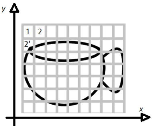
Figure 1: Picture of a cup in a grid
Figure 1 shows the picture of a cup that makes it easy to understand, an image, for a computer. The x-axis represents the rows, and the y-axis represents the column if we considered row and column as a pixel then there are 7*9= 63 pixels. A digital image can be regarded as a matrix having row and column with the function f[x,y] of two continuous variables x and y in which the computer identifies a point from the image. The corresponding matrix value determines the value of darkness at the location. In figure1 the image of a cup is considered to be in grayscale. For computers, the grayscale image has only one value of either black or white, but if the image is colored, then it has three channels of Red, Green, and Blue (RGB) color. So each pixel contains a particular value, the computer gives value according to the level of darkness. Here in Figure1, the image is in grayscale, the first row of the picture. Pixel 1 is color white so that the computer gives some value for that individual pixel, and similarly, the second column pixel 2’ of the image is black again; it gives a certain value for that pixel. As a result, for computer picture is a combination of numbers that are further processed and provides result with in the form of images.
3
2.1 Image Processing
Image processing is the process of manipulating images using computers and operates on images to extract the data or the information and execute some tasks from the related images.[1] A digital image is an array of the real and complex numbers represented by a finite number of bits. Digital image processing can be referred to as a numerical representation of the object to perform a series of operations by using different algorithms to get the desired output. With the development of image processing technology, it is used in various core research and development programs such as in engineering, medical, transportation, forensic examination, photography, weather forecasting, and other mobile technologies and many more areas.
These are the fundamental steps involved in image processing:
2.1.1 Image Acquisition
Image Acquisition is the first step, and the process of digital image processing, an image fi first captured by a photo sensor and send into digitizer for further processing to give the output. There are process like scaling, conversion to the grayscale from RGB, preprocessing to give the final output of image.[2]
2.1.2 Image Enhancement
Image enhancement is the process of adjusting the digital image by changing its brightness and contrasts, removing noise, and sharpen the image. The primary aim of an image enhancement technique is to bring out details of an image so that the image is more suitable for display and analysis as shown in Figure 2 .[2]
4
Figure 2: Image enhacnement [2]
2.1.3 Image Compression
Image compression is the most important aspect of image processing. Usually the sixe of image with high resolution is very big in size which need lots of memory. So to put images in the hand held device or to save memory of the device we need to reduce the size of the images by removing the image redundancy which is known as image compression.[2]
2.1.4 Morphological Processing
Morphological processing is the feature from which we can extract the features of the images like fingerprints recognition, face recognition, etc. Figure 3 represents the extraction of edge features from the binary image similarly in finger print recognition the lines and patterns from the finger print is extracted from fingers.[2]
5
Figure 3: Binary image with edge feature extraction[2]
2.1.5 Segmentation
Image segmentation can be referred to as the process of the partitioning of the image into multiple parts and segments. This technique is used to locate the boundaries. Such as lines, curves in an image, also assigning the label to every pixel of the image. Thus segmentation helps to simplify and change the representation of an image so that it is easier and meaningful to analyze. Image segmentation is very useful in grouping, and partitioning Figure 3 shows the example of image segmentation in text there each word is segemented with the red rectangle.[2]
6
2.1.6 Representation and Description
Representation and Description in image processing that follows the output of the segmentation stage. After segmentation, an image is further divided into the regions. The result of the segmented pixel is then represented and described in the characteristics features for computer processing, which is also used in the pattern recognition for efficient storage.[2]
2.1.7 Object Recognition
Object recognition is the process of identifying the object using computer vision technology and assigns a label to an object for the description.
2.1.8 Knowledge Base
Knowledge is the simple detailing regions of an image from where the information of interest is located, thus limiting the search which is conducted for seeking information. While it may be complex, such as an interrelated list of all significant defects in the materials inspection problem or an image with many databases such as high-resolution images of a region. Figure 5 represents the all the fundamentals of image processing that are related with the knwoledge base. By those different fundamental steps involved
7
in image processing the data are extracted to the knowledge base so that data can be easily extracted from knowledge base.[2]
Figure 5: Stages of Image Processing[2]
2.2 Types of Image Processing
2.2.1 Analog Image Processing
The analog image processing is applied only on analog signals, and it always works in two-dimensional signals. In analog signals, images that are formed after image processing are always varied because of the properties of time-varying signals due to which the image is not of good quality.
8
2.2.2 Digital Image Processing
Whereas digital image processing is applied to digital signals which work under image analyzing and manipulation of the images. The quality of the image is better. The digital image processing technique is cheaper as well as fast and very reliable it uses a good image compression method, which helps to reduce the amount of data required and helps to provide the good quality of images.
2.2.3 Optical image processing
Optical image processing is the processing of an image that is formed by a lens or mirror system by the reflection, refraction, or other properties of lights. This type of image processing is mostly used in the study of microscopic objects.
2.3 Color Model
A color model is a mathematical way of representing the colors, which can be described as a different combination of three or four different values of color components. While the combination of different values of color is associated with the description of how the components are interpreted. The result set of colors is called color space.[3] A color model is a specification and a subspace in a coordinate system, where each color is represented by a single point. So the color model is a system that creates a full range of color using the small sets of primary colors. Most colors are used in hardware or in the application where the color manipulation is done in several ways. While in digital image processing, mostly, the RGB color model is used in color monitors and digital cameras. Likewise, the CYMK color model is used in graphic designing printing. There is various type of color models used today depending upon the requirements, needs, and the applications. However, there is some important color model that is primarily used for image processing is discussed below.[3.4]
9
2.3.1 Additive color model (RGB)
The additive color model uses light to display the color. The primary purpose of using the RGB color model is to generate color for the electronic display system like monitors, televisions, and other display units. In this case, three-color Red, Green, and Blue are mixed in different combination to generate different colors. In RGB color model, each of the pixels consists of 3 values; one value is the brightness of Red another value is the brightness of Green, and last is the brightness value of Blue, and these three values are known as channels. So by varying the amount of Red, Green, and Blue color, all sorts of different colors can be created.[4] The RGB model is based on a cartesian coordinate system. Below, Figure 6 represents the schematic subspace of a cube where three corners of the cube are magenta, cyan, and yellow. Here the assumption of all the values for RGB is ranging from [0-1]. Black is the origin of the cube with the coordinates (0,0,0) blue is on the Y-axis with the coordinates (0,0,1) green with the coordinates (0,1,0) and red with the coordinates (1,0,0). The grayscale in the cube is the line joining the two points from black to white.
10
Images represented in the screen is the composition of three primary colors RGB. The number of bits used for the representation of each pixel in RGB space is known as pixel depth. Consider an image in which each red, green, and blue is an 8- bit image. Under this condition, each RGB color pixel has a depth of 24 bits. The total number of colors In the 24-bit image is (28)3 = 16,777,216 colors, which are shown in Figure 7 below.
Figure 7: Schematic of RGB 24-bit color cube[3]
2.3.2 Subtractive color model (CMYK)
CMYK color model, also known as subtractive color model. They are all about absorption or subtraction of certain wavelengths from white light, which act as the input source. The subtractive color model is used mostly in printing. CMYK refers to four inks Cyan, Magenta, Yellow, and Key (Black), as shown in Figure 8. This color model works by partially or entirely masking colors on a light, usually white background. When a surface coated with the cyan color is illuminated with white light, no red color is reflected from the surface because the cyan subtracts red light from the reflected white light, which is made itself with red, green, and blue light. Mostly all the printers use CMYK data input. Printing from a RGB image, we need to perform the conversion from RGB to CMYK In which the conversion is done with the matrix operation. [3]
11
[
𝐶
𝑀
𝑌
]
=
[
1
1
1
]
-
[
𝑅
𝐺
𝐵
]
And for the CMYK to RGB conversion.
[
𝑅
𝐺
𝐵
]
=
[
1
1
1
]
-
[
𝐶
𝑀
𝑌
]
Here the color value range from [0,1]
Figure 8 shows the color mode in which blue is formed with the addition of Cyan and Magenta; Red is formed with Magenta and Yellow, Green is formed with Cyan and yellow.
12
2.3.3 HSV color model
HSV corresponds to Hue, Saturation, and Value; it has fundamentally three components. Here Hue is the color; it can be signified as a point in a 360-degree color circle, as shown in Figure 9 in which 0 degrees represent Red, 120 degrees represents Green, 240 degrees represents Blue, and 300 degrees represents Magenta. Saturation is directly connected to the intensity of the color (range of gray in the color space). It is generally served in terms of percentage. [5]
Figure 9: HSV color model[5]
The range is from 0 to 100%. If it’s 100%, it signifies the intensity of color presence. Values can be referred to as brightness, and saturation is represented in the percentage. The range is from 0 and goes to 100%. '0' represents the black, and 100 percent represents the brightest.
2.3.4 YUV(YCbCr) color model
YUV is one of the color encoding systems, which is mostly used in the color image pipeline. It is used between an image source, a camera, and an image renderer of display systems. Here in the YUV model defines a color space in which Y is a luma component (Luminance) and two chrominance U (Blue projection) and V (Red projection). Luminance represents the brightness, and the chrominance represents the color, so it is also known as Luminance/Chrominance color system. The color is determined by
13
detaching the luminosity from the given color. The luminosity data gets into the Y channel, whereas UV carries different content. U channel shall be created after subtracting the Y from the amount of blue in the given image, coming to V, this channel gets created by subtracting the amount of Red from Y. The standard formula to derive the YUV from RGB is presented below:
Y = 0.299R + 0.587G + 0.114B
U = 0.492 (B-Y)
V = 0.877 (R-Y)
YUV is one of the most efficient options in image processing technology and application rather than traditional RGB display systems. Because, in YUV color encoding scheme, there are fewer transmission errors compared to RGB, also, the bandwidth is utilized very nicely so that the bandwidth is reduced.[6]
3
Computer Vision
Computer vision is one of the field of computer science and technology which enables us to see and identify, analyze, and process the objects around the surroundings. Computer vision is likely the technology that replicates human intelligence on seeing the objects analyzing it and give the results. This is a challenging task for the computer to identify and recognize the image from surrounding because humans have a better understanding of an object around there surroundings. From the beginning of human evolution, human has huge memory and data of an environment and surroundings from the thousands of year which computer don't have. But due to advancements in computer technologies, there are billions of stored data in a computer, which helps to make computers advanced on recognizing the images.[7]
Usually, computer vision refers to artificial intelligence as a computer must compares and interpret the surrounding what it sees around it and must perform the appropriate
14
tasks of analyzing the object, process it, and compare from the memory of the computer and give the result.[8] For an example of a jigsaw puzzle to make clear how computer vision works. At first, while solving the puzzle first, human has to make a mind or visualize how the final result is going to look like, so that's how the neural network in the computer takes action. Firstly, the computer analyzes different pieces of images and then identifies the edges and corner of the puzzle and tries to organize the pieces through the deep network layers as humans do. Even the computer doesn't have the final result of the puzzle. It uses the information and the images, which is fed by the many available related images and information; thus computer recognizes the object and gives the result.[9]
Computer vision technology is developing more and more due to the rapid rise of development in machine learning and artificial intelligence. Due to the development of object detection technology, it is used in a wide range. From daily use of face detection to unlock the mobile device or to open the door to the research in the cell division, DNA structures also in the space exploration, for the weather forecasting everywhere there is the use of this technology.
3.1 Machine Learning
Machine learning is the study of the algorithms and the statistical models that computer system uses for the specific task without the use of instruction or relying on some patterns and interference instead. A machine learning algorithm is created by collecting the data and then represent in the mathematical model, which helps to make the predictions and make the decision referencing from the mathematical model.[9] Machine Learning is used in a wide variety of field like in object detection, sorting of packages, filtering of documents, predicting the patterns which help perform the task very fast and more precisely than human. Machine learning is the science of making computers learn and act like humans by feeding the data and information without being explicitly programmed.
15
• Supervised learning
Supervised learning works under the supervision in which machine learns and trains data with the labeled dataset. Data that knows the target answer is called the label data, suppose if there is a dog that is labeled as a dog, then it is feed in the machine, which analyzes and learns the associations of the images based upon the features like color, shape, and sizes. So now, a machine can recognize the dog if the new unknown image without a label is fed in a machine, which is known as supervised learning. Supervised learning has a feedback mechanism. Mostly supervised algorithms use a decision tree, logistic regression, support vector machine.[10]
• Unsupervised learning
In unsupervised learning, the algorithm is trained with the data which is unlabeled; hence the machine tries to identify the patterns and give the response. Suppose if the data is given, which is not labeled, then the machine finds the structure and pattern in the data and groups them accordingly to the similarities, patterns. Unsupervised learning algorithms use k-means clustering, hierarchical clustering, apriori algorithm.[10]
• Reinforcement learning
Reinforcement learning si adapated from the supervised learning. But there is certaing difference between these two method of machine learning. In supervised learning the ouput result is already known but in reinforcement learning the output is unkown but here to retain ouput the best action is measured. Reinforcement learning is totally based upon reward based learning system. In Reinforcement learning, an agent interacts with its environment by producing actions and discovers errors or rewards. There is no predefined data; the input depends upon the actions taken by the agent. The action is then saved in the form of some data that helps as a memory for the agent. As the agent explores the environment, it will collect data, which is then used to get the output. Reinforcement learning algorithm use Q-Learning, SARSA.[10]
16
3.2 Object Detection
Object detection is the computer vision that deals with the identifying of the object and locating the object with certain classes in it with the help of the pictures, videos, or the camera feed. Object detection technology is used almost everywhere these days to make works easy, safe, and fast. The use of this technology is endless, like video surveillance, face detection, self-driving vehicles, cell count, and the list goes on.
Object detection before the advancement in deep learning was very lengthy and had several steps processes to execute. The first time face detection work in 2001 with the help of a viola-jones algorithm. They introduce to detect face by the help of webcam their algorithm only detect the face suppose if the face is in a different angle or downwards, then it would not detect. For this project, the primary process of detecting fire is inspired by the same algorithm proposed by the Viola-Jones face detecting algorithm.[11]
4
Methodology and Algorithm
Here in fire detection, we are using the Haar Cascade classifier, which is very popular in object detection through the image or any other video feeds. The algorithm is also known as the Viola-Jones algorithm because Paul Viola and Michael Jones developed it. The algorithm to detect fire is based on the machine learning concept using the Haar-like features, which is combined with the cascade classifier. To create a cascade classifier, many images so-called positive and negative images were uploaded for training into the computer. Positive images refer to the pictures in which fire is included, and negative images are just the background images that mean those images, which doesn't contain a fire in the images. For this training, more than 150 images were uploaded in which 75% of the images were positive, and 30% were negatives. In order to train the cascade classifier, almost double the amount of negative images must be uploaded because the cascade classifier is based upon appearance-based methodology. After uploading of images, there are two stages in the algorithm for detecting fire one is the detection and another is training algorithm which is explained below with the steps included in it:
17
4.1 Detection
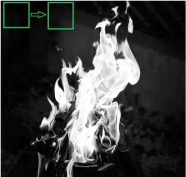
The procedure for detecting fire classifies images based on the value of simple features from an image. While detecting the fire, first of all, image is converted into grayscale since it is easy to work with, and it has less data rather than RGB color images. The algorithm outlines a box and searches for the fire in the image, as shown in Figure 10.(the box shows searching of fire) mainly, the box is searching for Haar-like features that are explained in further paragraphs. Along with small steps, the box detects the features like edges, brightness level from the image of fire, and then data collected by boxes are put together, which helps to determine where the fire is located.[13]
Figure 10: Rectangle box searching for features
4.1.1 Haar-like Features
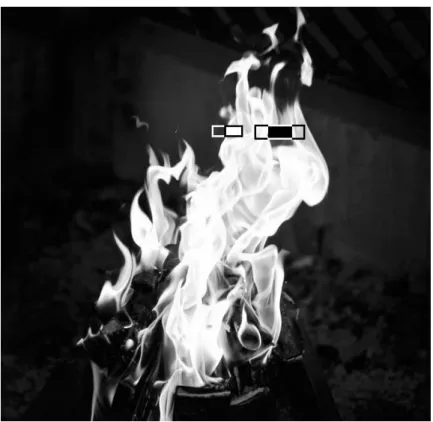
Haar features are similar to convolutional kernels, which are used to detect the presence of those features in the given image. As shown in Figure 11 the flame is in the grayscale has some features some of the regions are black, some regions are white, and some region is slightly darker or vice-versa from each other which helps the machine to understand an image. Due to this difference in brightness of an image, the Haar features like edge features, line features, center-surround features rectangle is moved around the
18
image, as shown in Figure 11. The rectangle box in Figure 11 of the color white and black is decided according to the region. Which compares the brightness and extracts features by assigning some values as it goes and inspects through that region in an image. [13]
Figure 11: Applying Haar-features
The white and black rectangular Haar-feature is explained by assuming the rectangle into a grid of size 4 x 4 each square represents as a pixel. In Figure 12a, every pixel is assigned with the intensity of white and black color in grayscale in which 0 represents a white pixel, and 1 represents a black pixel. But in a real scenario, the values of the pixel are different because the image doesn't have perfect white or perfect black intensities, which is shown in Figure 12b. After this, the algorithm will compare the real and ideal scenario by using the mathematical equation, as mentioned below, which will give a value of the particular feature. So here for the case.
19
Figure 12a: Ideal values Figure 12b: Real values
Δ = dark – white = 1 𝑛∑ 𝐼(𝑥) 𝑛 𝑑𝑎𝑟𝑘 − 1 𝑛∑ 𝐼(𝑥) 𝑛 𝑤ℎ𝑖𝑡𝑒
Δ for ideal image: 1 – 0 = 1
Δ for real image: 0.67 – 0.15 = 0.52
0.52 is the value of the real image. The closer the value to 1, the more likely to found a Haar-feature. Since this calculation is done only for a small amount of pixel, but in the real scenario, this type of intense calculation is being carried out several times, so to make it fast and reliable, another important part-integral image is carried out. [14]
4.1.2 Integral Image
The integral image plays an important role. It gives a boost to the calculation, which makes the approach as fast as possible because there are thousands of pixels that need to be calculated. While applying rectangular haar features the sum of pixels in unshaded rectangles sides are subtracted from the sum of the pixel in the shaded side of rectangles. Even for a small size images there are lots of features (over 160,000 for a 24x24 image). Since due to large number of features the algorithm requires iterating overall features, the features must be computed efficiently. So to solve this issue integral image is introduced.
Figure 13 shows the pixel's area in the rectangle. The sum of the pixel in rectangle D can be calculated with reference to four arrays. The value of the image at location 1 is the sum of pixels in a rectangle. Respectively value at position 2 is A+B, value at position
20
3 is A+C, and value at position 4 is A+B+C+D. So the sum within pixel D can be calculated as 4+1-(2+3). This calculation gives the actual value of the region, which is needed so that every time algorithm doesn't have carried out the repetitive calculation for the process.[12]
Integral image cuts out the time that will take to calculate the pixels. The integral image part is used to sum all the pixels of a particular box to its left and above ones. The four corner values of the area are to be calculated. This makes the summing of each pixel in the region. [14]
Figure 13: Pixel area in rectangle[12]
4.2 Training and Learning
After extracting features from an image to detection. The machine is now trained to identify the features from the input. So it is fed with lots of information so that it can predict objects from the information. For these, the image is shrunk into size 24x24 from this; the algorithm looks for the features. To train the machine, It needs a lot of pictures of fire, different fireplaces, conditions of fire, also known as a positive image. Concerning that, many negative images were uploaded. The negative image refers to pictures in which fire is not included in an image. Negative images are uploaded so it can differentiate between the two classes, which helps to an algorithm which features are more likely to be a fire and which are not expected to be fire. The next step is to use the AdaBoost technique and cascading technique to make powerful classification and accuracy in recognizing the flame.[13]
21
4.2.1 Adaptive Boosting (Ada Boost)
Adaboost algorithm is a learning algorithm used to train the classifier and selects the best subset of features. The algorithm learns from the data that is given and determine the false positive and true negatives in data. For an equation:
F(x)= a1f1(x) + a2f2(x) + ....
Here F(x) is the strong classifier, and a1f1(x), a2f2(x) are weak classifiers where a1, a2
are the weights, and f1, f2 are the features. So the strong classifier is made up of many weak classifiers since one weak classifier is not good as adding more classifiers makes the algorithm stronger and accurate, which is called an ensemble.[14]
4.2.2 Cascading
Cascade classifier is used for the accuracy of identification. It is composed of several stages consisting of a strong classifier. Those strong classifiers are passed by So all the features are grouped in several stages where each stage has a certain number of features. The use of these several stages is used to determine whether the given input subwindow has features of fire or not if there are no features of fire, then the given sub-window is discarded and fails to go for other stages. Figure 14 shows a schematic description of cascade detection.[13]
Here instead of using all the features more than 6000 in a window, the features are a group in different stages of classifiers as shown in Figure 14, there are some stages stage 1 and stage 2. Usually, the first few stages will contain very less numbers of features. If the window fails, it is discarded if not apply the second stage of features and continue the process. The window or stage which passes all the features of fire, then it is detected as fire.
22
Figure 14: Schematic Description of cascade detection
4.3 System Design
For this system fire detection using image processing, we are using Raspberry Pi 3 Model B as a processing device. It is the main computer for all the code and image processing. As shown in the block diagram Figure 15 the Raspberry Pi is connected with USB Camera. The USB camera is a primary source of input for processing the live video that fetches through the USB camera. After processing of video, which is done by using the Haar Cascade Classifier algorithm, the system continuously monitors the surroundings. If there is a fire in the surroundings, the webcam detects the fire or flame then the user gets fire alert. If there is no fire in the scene, then the video is continuously processed in the code until the fire is detected, so if there is fire, then the only user gets the alert of fire. The block diagram Figure 15 below shows the steps of the system.
23
Figure 15: Block Diagram
4.4 Algorithm
The first step is the training of the classifier, as mentioned early. Training for the highly accurate classifier needs lots of time and processing power, so here we only used a little number of pictures.
After training the fire cascade classifier, the captured frame from the webcam is converted into grayscale. The reason for converting frame into grayscale is because the frame captured by webcam is in RGB color. Since RGB images have three channels of colors, so if the image is converted into grayscale, there will be only one channel, either black or white, which is easy to process. After the conversion, the fire classifier is used with inbuilt function detecMultiscale, which will help to find the features and location of images. Parameters like scale factor and min neighbor are passed. These factors are an essential factor in detecting fire. A scale factor is used for creating of scale pyramid because while training the classifier fixed size of the image is trained, so the scale factor will allow rescaling the size of an input frame to detect the fire. Another parameter min
24
neighbor will determine the quality of an image here for thesis min neighbor factor is given 7. [19]
4.5 Flowchart
Figure 16: Flowchart
Figure 16 is the flowchart of the system that shows the working system. Firstly the video is fed through the webcam, and the video is then forwarded into Raspberry Pi for processing. It will use a cascade classifier to compare the image which is available in the classifier. If a fire is detected, the code will execute, and there will be the fire alert message, and if a fire is not detected, then the system will continue; there will be no alert of fire. The system stays in the same loop until the fire is detected in the aim place.
25
4.6 Result
The main goal of the thesis was to make a prototype fire detector system. After the completion of the code and installed in the Raspberry Pi, the fire was detected. Figure 17 shows the detection of fire, and in Figure 18 fire is not detected because of the distance and the size of the flame. For the system the flame is look like a small led bulb so it is hard to detect.
26
Figure 18: Fire not detected
Finally, the result shows the fire is detected. In Figure14, there is a green rectangle box that appears when the flame has detected. The size of the rectangle is varied in the case how large the fire is. So while coding, some threshold values have been given for the rectangle to detect the fire region correctly. The threshold value is provided by setting the parameters for the value of scale factor in the case of this project 1.1 is the scale factor, and 7 is the min neighbor. The scale factor is used for the control of the image pyramid while detecting the object. If the scale factor is too big, then it will be difficult to identify the object. Hence it will be less accurate, and if the scale factor value is less than there will be false detection. Since the experiment was conducted in the room light condition, the scale factor is also calibrated according to the room light to get the accurate result.
27
5
Embedded system
An embedded system is the computer system with a combination of software and hardware that has the processing power, input-output functions with computer memory. Which is designed particular purposes to perform the specific tasks in the given time. They are used in the larger systems like in the industry, farming, automobiles, household appliances, etc. embedded systems can be both user interface UI or the complex graphical user interface GUI. [14]An embedded system is based upon the microcontroller or the microprocessors. Here the microcontroller or microprocessors are used for processing, and there is a need for other components like memory chips, which are designed for the specific system.
There are many characteristics of embedded systems like it has very sophisticated functionality for each appliance. It has a very low manufacturing cost. The embedded system is designed for specific tasks. It also has advantages of low power consumption because of the use of microcontrollers they don't take so much power to perform the tasks. Here the embedded system is designed for the application-dependent processor, not the general-purpose processor like in the computers. [15]
28
Figure 19 shows the system design calls of an embedded system. Embedded systems are used in the various field; it is the backbone of the automatic system. Embedded systems are used in the diverse field of engineering, like control engineering, operating systems, IC designing, Computer Architecture, Digital Electronics, Analog Electronics, Data Communication, Software Engineering.
5.1 Raspberry Pi 3
Raspberry Pi is the single board computer sized of the credit card, which is inexpensive, and due to its size, it is good for the portability and usability so that it can be used and placed wherever desired. Raspberry Pi 3 is the third model of the raspberry family. Raspberry Pi is based upon the Linux-based operating system with the quad-core ARM CPU with the processor speed of 700Mhz to 1.4 GHz. It has a 1GB of RAM with the 4 USB,1 Ethernet, Headphone, one micro SD slots, and one HDMI ports. And the lower level output of 40 GPIO pin which allows connecting with everything like camera, motors whole other things. Raspberry is mainly designed for promoting the teaching of computers and technology using different programming languages. But due to its cost and modification, Raspberry Pi became very popular with all-around people who are interested in robotics and technology. Raspberry Pi is not usually used for the general-purpose computer because it is more capable of doing some specific task.[19]
29
Figure 20: GPIO Pins[19]
5.2 Software Requirements
The application is based upon the python language, which is high-level programming language easy to use, and with the python, the system uses the open CV library for all the image processing systems. Also, the system here uses Raspberry Pi as a central processing unit pi is more suitable for the python because it is preinstalled in the OS of the Raspberry Pi.
5.2.1 Python
Python is considered as the general-purpose, high-level programming language. With the python, the readability of code is enhanced, compared to another language like C, C++, java. The use of many syntaxes and the procedure of writing code is way too difficult to read and lengthy. Whereas in python, there are fewer lines of code. The major point of using python is the simplicity and compatibility of the code. Python also supports
30
multiple libraries and frameworks, which makes easy and gives more space for developers to create and complete the project. Some of the libraries which are used in the system is NumPy. It is an important library for the multidimensional array function, matplotlib, which is the plotting library that gives the visual datasets and also helpful for the statistical analysis of the data. Due to simplicity, mostly python is used in R&D. Mostly nowadays, python is used for Machine Learning and Artificial Intelligence.[20]
5.2.2 Open CV
OpenCV is an open-source package and machine learning library, which is designed for real-time computer vision applications. Open CV is the cross-platform library that supports many programming languages like Python, Java, C++, C, etc. This library is originally designed by the Intel corporation and free for use under the open-source BSD license. It is one of the most widely used libraries for implementing video detection, image detection, deep learning application, machine learning, human-computer interaction, 2D, and 3D feature toolkits. The library has more than 2500 algorithms, which include both computer vision and machine learning algorithms.[20]
Some of the syntaxes that are used in the program are: Import cv2 # used for importing the open cv library Import NumPy as np # importing the NumPy array
Cv2.VideoCapture() # used for capturing the video from the camera
Cv2.cvtColor() # used for converting an image from one color space to another gray = cv2.cvtColor(resized, cv2.COLOR_BGR2GRAY)# used for converting RGB color to gray
fire = fire_detection.detectMultiscale(gray, 1.1, 7) # using fire classifier in which objects are loaded with the fire_detection.xml
#detetctMultiscale
A multi-scales detection algorithm is another important steps in the fire de-tection algorithm. This feature is used in order to detect the fire of any size because the size of the fire is unknown.since learning and testing are based on rectangular feature, those features should be calculated in anyscale. In this project, we used the scales by a factor of 1.1. In each iteration, the width and height of the rectangle will increase to 1.1 times of the previous one. Another parameter is minNeighbors, which is 7 in the project; this parameter specifies how many neighbors each candidate rectangle should retain it. The parameter directly affects the quality of detected fire, higher-value results in less detection of fire with a high-quality result.[18]
31
6
Limitations and Future Improvements
Due to safety reasons, the effectiveness of the system cannot be tested in the full phase, so here for the prototype demo, the lighter is used as the source of fire as it has the same features and characteristics of the fire. There are some limitations to the prototype. There is some error in detection when the fire is far away from the camera because of the size of the flame.
The project was done with different methodology as well by using RGB color model concept, the RGB filter was used to extract Red, Green and Blue components for each pixel in the frame and then every pixel from the frame was passed through the condition:
• If R>G>B
• If R>Rt(threshold value 0-255). which is based upon the intensity of light in a particular environment.
The result of this methodology was moderate and not so successful. Every time if there is a light source with the same color value of fire, the system detects it as a fire. Figure 21a and Figure 21b shows the result. The practical was conducted in the room. The light source shown in Figure 21a has almost the same value as a color of fire, and the system detects it as fire, as shown in Figure 21b.
Figure 21a: Light with color as fire Figure 21b: Flame is detected due to same color value of fire
32
The system can be made more accurate and precise by using other machine learning algorithms like YOLO(You Only Look Once), Tensorflow, Keras algorithm, neural network like CNN, RCNN, which are more advanced than the current algorithm used for this project. Further, this system can be modified more like using an IP camera with Raspberry Pi and survey the surroundings staying far from the actual place. The system can be used in various areas like in parking lots to check the vehicle has paid the parking fee. Counting the number of cars passing through the particular junction, which helps to store data for the improvements in road traffic congestions, agriculture, farming, there are many uses of object detection.
7
Conclusion
The project aimed to detect fire with a different approach rather than using an existing system. Currently, systems like a smoke detector and sprinkler water discharge systems are used, which are very useful and work at its best. But there are certain limitations to these systems. The thesis is conducted to optimized the current system. As technology is getting better and better as to keep it up with the technology and to minimize the limitations also, the new system has created.
By using image processing technology for detecting the fire, these limitations can be reduced because in this system camera acts like a human eye, as it detects a fire, the video is captured, and the image is processed using the software alert user. Thanks to Raspberry Pi, because of the size, cost-effectiveness, simplicity, and portability, it can be used everywhere. The prototype successfully detects fire. The thesis gives the review analysis, designing system, and algorithm, test, and result.
33
References
1. Science Direct. Image Processing. [online]
URL: https://www.sciencedirect.com/topics/engineering/image-processing
Accessed on November 26, 2019
2. Ques10. What is Image Processing? Explain the fundamentals of Image Processing [online]
URL: https://www.ques10.com/p/33595/what-is-image-processing-explain-fundamental-steps/
Accessed on November 26, 2019 3. Color Model. Wikipedia [online]
URL: https://en.wikipedia.org/wiki/Color_model
Accessed on November 30, 2019
4. Understanding Color Models and Spot Color System [online]
URL: http://www.designersinsights.com/designer-resources/understanding-color-models/
Accessed on November 30, 2019
5.HSL and HSV Color Model. Wikipedia [online] URL: https://en.wikipedia.org/wiki/HSL_and_HSV
Accessed on December 04, 2019
6.YCbCr Color Model. Wikipedia [online] URL: https://en.wikipedia.org/wiki/YCbCr
Accessed on December 04, 2019
7. Techopedia. What is Computer Vision? [online]
URL: https://www.techopedia.com/definition/32309/computer-vision
Accessed on December 04, 2019 8. Computer Vision. Wikipedia [online]
URL: https://en.wikipedia.org/wiki/Computer_vision
Accessed on December 04, 2019 9.Machine Learning. Wikipedia [online]
URL: https://en.wikipedia.org/wiki/Machine_learning
Accessed on December 10, 2019
10.Expert System. What is Machine Learning? [online] URL: https://expertsystem.com/machine-learning-definition/
34
11.Object Detection. Wikipedia [online]
URL: https://en.wikipedia.org/wiki/Object_detection
Accessed on December 14, 2019
12.Viola-Jones Object Detection paper. [online]
URL: http://bit.ly/C_RapidObjectDetectPaperAccessed on December 15, 2019 13. The Startup. Breaking Down Facial Recognition [online]
URL: https://medium.com/swlh/the-intuition-behind-facial-detection-the-viola-jones-algorithm-29d9106b6999
14. Viola-Jones paper[online]
URL: https://www.cs.cmu.edu/~efros/courses/LBMV07/Papers/viola-cvpr-01.pdf
15.Open CV. Face Detection Using Haar Cascade [online] URL:
https://opencv-python-tutroals.readthedocs.io/en/latest/py_tutorials/py_objdetect/py_face_detection/py_face_ detection.html
Accessed on December 18, 2019
16.Embedded Systems. Wikipedia [online]
URL: https://en.wikipedia.org/wiki/Embedded_system
Accessed on December 24, 2019
17.TechTarget.Embedded Systems [online]
URL: https://internetofthingsagenda.techtarget.com/definition/embedded-system
Accessed on December 24, 2019 18.Project Report EE700 [online]
URL:http://www.ece.lsu.edu/ipl/SampleStudentProjects/ProjectChen/report%20of%20f ace%20tracking.pdf
19. Raspberry Pi.Wikipedia [online]
URL: https://en.wikipedia.org/wiki/Raspberry_Pi
Accessed on December 26, 2019 20.Open CV. Wikipedia [online]
URL: https://en.wikipedia.org/wiki/OpenCV
Accessed on December 27, 2019 21. Python.Wikipedia [online]
URL: https://en.wikipedia.org/wiki/Python_(programming_language)
![Figure 2: Image enhacnement [2]](https://thumb-us.123doks.com/thumbv2/123dok_us/1867801.2772400/9.892.302.691.128.333/figure-image-enhacnement.webp)
![Figure 3: Binary image with edge feature extraction[2]](https://thumb-us.123doks.com/thumbv2/123dok_us/1867801.2772400/10.892.271.711.128.389/figure-binary-image-edge-feature-extraction.webp)
![Figure 5: Stages of Image Processing[2]](https://thumb-us.123doks.com/thumbv2/123dok_us/1867801.2772400/12.892.201.617.287.601/figure-stages-of-image-processing.webp)
![Figure 6: Schematic of RGB color[3]](https://thumb-us.123doks.com/thumbv2/123dok_us/1867801.2772400/14.892.379.659.606.859/figure-schematic-of-rgb-color.webp)
![Figure 7: Schematic of RGB 24-bit color cube[3]](https://thumb-us.123doks.com/thumbv2/123dok_us/1867801.2772400/15.892.324.653.271.593/figure-schematic-rgb-bit-color-cube.webp)

![Figure 9: HSV color model[5]](https://thumb-us.123doks.com/thumbv2/123dok_us/1867801.2772400/17.892.247.668.382.689/figure-hsv-color-model.webp)