Programming Research Group, Faculty of Science, University of Amsterdam
ABSTRACT
In previous work we described how the process algebra based language PSF can be used in software engineering, using the ToolBus, a coordination architecture also based on process algebra, as implementation model. In this article we summarize that work and describe the software development process more formally by presenting the tools we use in this process in a CASE setting, leading to the PSF-ToolBus software engineering environment. We generalize the refine step in this environment towards a process algebra based software engineering workbench of which several instances can be combined to form an environment.
Ke ywords: process algebra, software engineering, software architecture, workbench, environment
1. Introduction
In [10-12], we investigated the use of process algebra, in particular the process algebra based language PSF (Process Specification Formalism), in the software development process. We used the ToolBus, a process algebra based coordination architecture, as implementation model. We giv e a description of PSF and the ToolBus in sections 1.2 and 1.3. This work resulted in two libraries for PSF, one for software architecture specification, and one for specifying the software as ToolBus application. We obtain a ToolBus application specification by refining an architecture specification with the use of vertical and horizontal implementation techniques. The components in the ToolBus application specification can be implemented separately and connected to the ToolBus which is controlled by a ToolBus script that can be derived from the ToolBus application specification. This technology has been successfully used in a new implementation of the simulator from the PSF Toolkit and an integrated development environment (IDE) for PSF.
In this paper we summarize the software development process with PSF and give an example. We describe this software development process more formally by presenting the tools we use in the development process in a Computer-Aided Software Engineering (CASE) setting. We then generalize the refine step from architecture specification to ToolBus application specification in this environment towards a process algebra based software engineering workbench.
In the remainder of this section we give a description of CASE technology and the terminology we use, followed by brief descriptions of PSF, and of the ToolBus.
1.1 Computer-Aided Software Engineering
Since the early days of developing software, tools are used to assist in the developing process. In the beginning these were the tools provided by the operating system, such as editors, compilers, and debuggers. With the demand for larger software systems, the development process became more complex and expensive, and a need to improve and control the development process arose. One of the technologies to achieve this is computerized applications supporting and (partially) automating software-production activities. This resulted in many tools for all kinds of activities in the software development process, from editing and testing tools to management and documentation tools.
With the growth in development and use of these tools also the terminology to denote the function and activities of these tools increased. This terminology is often confusing or misleading. To reason on CASE technology it is necessary to use a fixed terminology. We use the terminology as proposed by Fuggetta in [18] which has since then been used by many others. The following three categories are used for
classifying CASE technology. Tools
support individual process tasks. Workbenches
support process phases or activities and normally consist of a set of tools with some degree of integration.
Environments
support at least a substantial part of the software process and normally include several integrated workbenches.
1.2 PSF
PSF is based on ACP (Algebra of Communicating Processes) [3] and ASF (Algebraic Specification Formalism) [4]. A description of PSF can be found in [13, 14, 22, 23]. Processes in PSF are built up from the standard process algebraic constructs: atomic actions, alternative composition+, sequential composition ., and parallel composition || . Atomic actions and processes are parameterized with data parameters. PSF is accompanied by a Toolkit containing among other components a compiler and a simulator that can be coupled to an animation [15]. The tools operate around the tool intermediate language (TIL) [24]. Animations can either be made by hand or be automatically generated from a PSF specification [16]. The animations play an important role in our software development process as they can be used to test the specifications and are very convenient in communication to other stakeholders.
1.3 ToolBus
The ToolBus [5] is a coordination architecture for software applications developed at CWI (Amsterdam) and the University of Amsterdam. It utilizes a scripting language based on process algebra to describe the communication between software tools. A ToolBus script describes a number of processes that can communicate with each other and with various tools existing outside the ToolBus. The role of the ToolBus when executing the script is to coordinate the various tools in order to perform some complex task. A language-dependent adapter that translates between the internal ToolBus data format and the data format used by the individual tools makes it possible to write every tool in the language best suited for the task(s) it has to perform.
ToolBus
PT1 Adapter Tool 1 PT2 Tool 2 AdapterFigure 1. Model of tool and ToolBus interconnection
In Figure 1 two possible ways of connecting tools to the ToolBus are displayed. One way is to use a separate adapter and the other to have a builtin adapter. Processes inside the ToolBus can communicate with each other using the actionssnd-msgandrec-msg. ToolBus processes can communicate with the tools using the actionssnd-doandsnd-eval. With the latter a tool is expected to send a value back which can be received by the process with the actionrec-value. A tool can send an event to a ToolBus
process which can be received with the actionrec-event. Such an event has to be acknowledged by the ToolBus process with the actionsnd-ack-event.
2. Software Engineering with PSF
A software design consist of several levels, each lower one refining the design on the higher level. The highest level is often referred to as the architecture, the organization of the system as a collection of interacting components. In conventional software engineering processes, the architecture is usually described rather informally by means of a boxes-and-lines diagram. Following a lot of research going on in this area architectural descriptions are becoming more formal, especially due to the introduction of architectural description languages (ADL’s). A specification in an ADL can be refined (in several steps) to a design from which an implementation of the system can be built. We hav e developed a library for PSF to specify software architecture.
In software engineering and reengineering it is common practice to decompose systems into components that communicate with each other. The main advantage of this decomposition is that maintenance can be done on smaller components that are easier to comprehend. To allow a number of components to communicate with each other a so-called coordination architecture will be required. In connection with PSF we will make use of the ToolBus [5] coordination architecture. We hav e developed a library for PSF to specify ToolBus applications. It does not contain all functionality from the ToolBus but just what is needed for our purposes.
In the following sections we briefly describe the PSF library for specifying software architectures (formalizing the boxes-and-lines diagram), the PSF library for specifying ToolBus applications, and the implementation techniques we use to get from an architecture specification to a ToolBus application specification. We also give an example of how to use the libraries and how to apply the implementation techniques.
2.1 Software Arc hitecture Specification
We specify software architecture in PSF with the use of a PSF library providing architecture primitives. The primitives aresndandrecactions for communication, each taking a connection and a data term as argument. A connection can be built up with a connection function>>with two identifiers indicating a component as argument. Processes describing the software architecture with these primitives can be set in an architecture environment, also provided by the PSF library. The architecture environment takes care of encapsulation to enforce the communication between the processes.
2.2 ToolBus Application Specification
A specification of a ToolBus application consists of specifications for the processes inside the ToolBus, the ToolBus script, and specifications for the tools outside the ToolBus with which the ToolBus processes communicate. There are two sets of primitives, one set for communications between the processes inside the ToolBus, and one set for communications between the ToolBus processes and the tools. The first set consists oftb-snd-msgandtb-rec-msgeach taking three arguments, the identifier of the sender, the identifier of the receiver, and a term representing a message. The second set consists of the ToolBus process actionstb-rec-event,tb-snd-ack-event,tb-snd-do,tb-snd-eval, and tb-rec-value, taking a tool identifier and a term as arguments, and the tool actions tooltb-snd-event,
tooltb-rec-ack-event,tooltb-rec,tooltb-snd-value, taking a single term as argument. 2.3 From Arc hitecture to ToolBus Application Design
It is only useful to invest a lot of effort in the architecture if we can relate it to a design on a lower level. In this section we describe the implementation techniques we use to get from an architecture specification to a ToolBus application specification. These techniques are important in our software engineering process for they compress a large number of algebraic law applications into a few steps and so make the process feasible. We demonstrate these techniques with a toy example in section 2.4.
Horizontal Implementation
Given two processes S and I , I is an implementation of S if I is more deterministic than (or equivalent to) S. As the actions S and I perform belong to the same alphabet, S and I belong to the same abstraction level. Such an implementation relation is called horizontal.
To achieve a horizontal implementation we use parallel composition, which can be used to constrain a process. Consider process P=a . P, which can do action a at every moment. If we put P in parallel with the process Q=x . b . Q with communication a | b=c and enforcing the communication by encapsulation, process P can only do action a whenever process Q has first done action x. So process P is constrained by Q and P || Q is an horizontal implementation of P, provided Q only interacts with P through b. This form of controlling a process is also known as superimposition [8] or superposition [20].
Vertical Implementation
In [32], action refinement is used as a technique for mapping abstract actions onto concrete processes, called vertical implementation, which is described more extensively in [33]. With vertical implementation we want to relate processes that belong to different abstraction levels, where the change of level usually comes with a change of alphabet. For such processes we like to dev elop vertical implementation relations that, given an abstract process S and a concrete process I , tell us if I is an implementation for the specification S. More specifically, we want to develop a mapping of abstract actions to sequences of one or more concrete actions so that S and I are vertical bisimular.
We giv e a rationale of vertical implementation. Consider the processes P=a . b with a an internal action and Q=c . d . e with internal actions c and d. If we refine abstract action a from process P to the sequence of concrete actions c . d and rename action b to e we obtain process Q. The processes P and Q are vertical bisimular with respect to the mapping consisting of the above refinement and renaming.
We can explain the notion vertical bisimular by the following. We hide the internal action a of process P by replacing it with the silent stepτ to obtain P=τ. b. Applying the algebraic law x .τ = x gives us P=τ .τ . b. If we now replace the firstτ with c and the second with d, and rename b into e we obtain the process Q. With H as hide operator and R as renaming operator we can prove that R{b→e}(H{a}(P)) and
H{c,d}(Q) are rooted weak bisimular (see Figure 2). So vertical bisimulation is built on rooted weak
bisimulation as horizontal implementation relation.
P = a . b Q = c . d . e a→c . d b→e τ. e R{b→e}H{a} τ.τ. e H{c,d} ↔ rw
Figure 2. Implementation relations 2.4 Example
We show our development process for a small application. In this example, Tool1 can either send a
messageto Tool2 and then wait for an acknowledgement from Tool2, or it can send aquitafter which the application will shutdown.
Architecture Specification
We first specify a module for the data and id’s we use. data module Data
begin exports begin functions message : → DATA ack : → DATA quit : → DATA c1 : → ID c2 : → ID end imports ArchitectureTypes end Data
We then specify the system of our application. process module ApplicationSystem begin exports begin processes ApplicationSystem end imports Data, ArchitecturePrimitives atoms send-message stop processes Component1 Component2 definitions Component1 = send-message . snd(c1 >> c2, message) . rec(c2 >> c1, ack) . Component1 + stop . snd-quit Component2 = rec(c1 >> c2, message) . snd(c2 >> c1, ack) . Component2
ApplicationSystem = Component1 || Component2 end ApplicationSystem
Thesnd-quitin the process definition for Component1 communicates with the architecture environment followed by a disrupt to end all processes.
Next, we put the system in the architecture environment by means of binding the main process to the System parameter of the environment.
process module Application begin imports Architecture { System bound by [ System→ ApplicationSystem ] to ApplicationSystem renamed by [ Architecture → Application ] } end Application
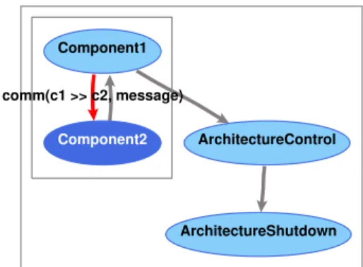
The generated animation of the architecture is shown in Figure 3. Here, Component1 has just sent a message to Component2, which is ready to send an acknowledgement back.
Component1
Component2
ArchitectureShutdown ArchitectureControl comm(c1 >> c2, message)
Figure 3. Animation of an example architecture
Each box represents an encapsulation of the processes inside the box, and a darker ellipse is a process which is enabled to perform an action in the given state.
The module mechanism of PSF can be used to build more complex components hiding internal actions and sub-processes. With the use of parameterization it is even possible to make sev eral instances of a component.
ToolBus Application Specification
We make a ToolBus application specification for our example in the form shown in Figure 1. By refining the specification of the architecture we obtain a ToolBus application specification for our example. Take the processComponent1from the architecture specification of our toy example.
Component1 = send-message . snd(c1 >> c2, message) . rec(c2 >> c1, ack) . Component1 + stop . snd-quit
We can make a virtual implementation by applying the mapping consisting of the refinements snd(c1 >> c2, message)→ tb-snd-msg(t1, t2, tbterm(message))
rec(c2 >> c1, ack) → tb-rec-msg(t2, t1, tbterm(ack)) . tb-snd-ack-event(T1, tbterm(message))
snd-quit → snd-tb-shutdown
and the renamings of the local actions
send-message → tb-rec-event(T1, tbterm(message))
stop → tb-rec-event(T1, tbterm(quit))
Renaming the processComponent1intoPT1gives the following result. PT1 = tb-rec-event(T1, tbterm(message)) . tb-snd-msg(t1, t2, tbterm(message)) . tb-rec-msg(t2, t1, tbterm(ack)) . tb-snd-ack-event(T1, tbterm(message)) . PT1 + tb-rec-event(T1, tbterm(quit)) . snd-tb-shutdown
We can show that Component1 and PT1 are vertical bisimular. Applying the renamings on process
Component1and hiding of the actions to be refined results in Component1’ =
tb-rec-event(T1, tbterm(message)) . τ . τ . Component1’ + tb-rec-event(T1, tbterm(quit)) .τ
Hiding of the actions in the refinements in processPT1results in PT1’ =
tb-rec-event(T1, tbterm(message)) . τ . τ .τ . PT1’ + tb-rec-event(T1, tbterm(quit)) .τ
It follows thatComponent1’↔rwPT1’.
We now make a horizontal implementation by constrainingPT1withTool1Adapter. PTool1 = Tool1Adapter || PT1
Tool1Adapter is itself an constraining of AdapterTool1 with Tool1 for which we give the definitions below. AdapterTool1 = tooladapter-rec(message) . tooltb-snd-event(tbterm(message)) . tooltb-rec-ack-event(tbterm(message)). tooladapter-snd(ack) . AdapterTool1 + tooladapter-rec(quit) . tooltb-snd-event(tbterm(quit)) Tool1 = snd(message) . rec(ack). Tool1 + snd(quit)
In this constraint, the communication between the actions tooladapter-rec and tooladapter-sndofAdapterTool1and the actionssndandrecofTool1are enforced.
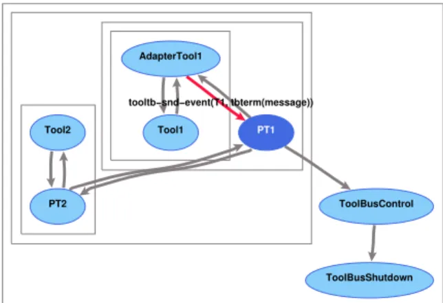
An implementation forComponent2can be obtained in a similar way. A generated animation is shown in Figure 4, in which AdapterTool1 just sent a message it had received from Tool1, to ToolBus process PT1.
PT1 ToolBusControl Tool1 ToolBusShutdown PT2 Tool2 AdapterTool1 tooltb−snd−event(T1, tbterm(message))
Figure 4. Animation of the ToolBus specification example Implementation
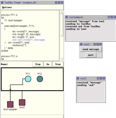
The implementation consists of three Tcl/Tk [31] programs (Tool1, its adapter, and Tool2), and a ToolBus script. A screendump of this application at work together with the viewer of the ToolBus is shown in Figure 5. With the viewer it is possible to step through the execution of the ToolBus script and view the variables of the individual processes inside the ToolBus. The ToolBus script is shown below. The
executeactions in the ToolBus script correspond to starting the adapter for Tool1 and starting Tool2 in parallel with the processesPT1andPT2respectively.
process PT1 is let T1: tool1adapter in execute(tool1adapter, T1?) . ( rec-event(T1, message) . snd-msg(t1, t2, message) . rec-msg(t2, t1, ack) .
Figure 5. Screendump of the example as ToolBus application with viewer snd-ack-event(T1, message) + rec-event(T1, quit). shutdown("") ) * delta endlet process PT2 is let T2: tool2 in execute(tool2, T2?) . ( rec-msg(t1, t2, message) . snd-eval(T2, eval(message)). rec-value(T2, value(ack)) . snd-msg(t2, t1, ack) ) * delta endlet
tool tool1adapter is { command = "wish-adapter -script tool1adapter.tcl" } tool tool2 is { command = "wish-adapter -script tool2.tcl" }
toolbus(PT1, PT2)
The processes in the ToolBus script use iteration (*, where P * delta repeats P infinitely) and the processes in the PSF specification use recursion. In PSF it is also possible to use iteration in this case, since the processes have no arguments to hold the current state. On the other hand, in PSF it is not possible to define variables for storing a global state, so when it is necessary to hold the current state, this must be done through the arguments of a process and be formalized via recursion.
Following the description of the ToolBus processes is the description of how to execute the tools by the execute actions. The last line of the ToolBus script starts the processesPT1andPT2in parallel.
3. The PSF-ToolBus Software Engineering Environment
Development of a software system starts with the specification of its architecture. This architecture specification consists of components that communicate with each other. We make use of the PSF Architecture library that provides the primitives we use in the architecture specification. The system
consists of the components put together in parallel. The system is then put in an architecture environment that enforces the communications embedded in the specifications of the components Since the system and the environment are always built in the same way, we can easily generate them. So specification of an architecture is limited to specification of the components. This gives an architecture workbench as shown in Figure 6. Objects to be specified are presented asbold boxes, workbench tools asellipses, and generated objects asslanted boxes.
PSF Arch Lib Components System Env
Architecture specification
generate Arch
Figure 6. The Architecture Workbench
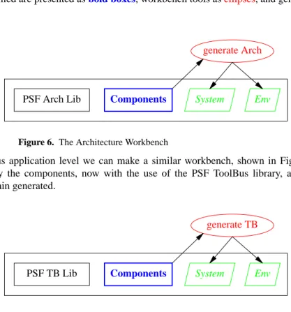
For specification at the ToolBus application level we can make a similar workbench, shown in Figure 7. Again we only need to specify the components, now with the use of the PSF ToolBus library, and the system and environment are again generated.
PSF TB Lib Components System Env
ToolBus application specification
generate TB
Figure 7. The ToolBus Workbench
To derive a ToolBus application specification from an architecture specification we refine the abstract actions in the architecture specification to sequences of actions on the ToolBus application level. The refinement can be done automatically by applying a set of mappings on the specification of the components, resulting in the specification of a set of ToolBus processes. We constrain these ToolBus processes with (abstract) specifications of the tools. The constraining can also be done automatically and results in the specification of the components for the ToolBus application specification.
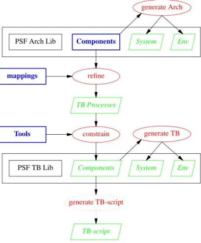
Combining the workbenches for architecture level and ToolBus level design and integrating the refine and constrain steps, we get the PSF-ToolBus software engineering environment shown in Figure 8. We see that the components for the ToolBus application are generated, so we only have to specify the components on the architecture level and give proper mappings and constraints (the tools) to obtain a ToolBus application specification.
Also shown in Figure 8 is a generation step of a ToolBus-script from the components of the ToolBus application specification. This step is still to be made by hand since PSF specifications use recursion for setting the state of a process, and the ToolBus cannot handle recursive processes. ToolBus scripts use iteration with variable assignment for keeping track of the state of a process.
4. A Generalized Process Algebra Software Engineering Environment
The Tools in Figure 8 can also be ToolBus application specifications developed in a similar way. Howev er, the refining of architecture specifications is not limited to the level of ToolBus application specifications. Other levels of design, and even sev eral levels of refinement connected in series are possible.
In the following sections we generalize the concept from the PSF-ToolBus software engineering environment.
PSF Arch Lib Components System Env
Architecture specification
generate Arch
PSF TB Lib Components System Env
ToolBus application specification generate TB refine mappings TB Processes constrain Tools generate TB-script TB-script
Figure 8. The PSF-ToolBus SE Environment
4.1 A Generalized PSF Software Engineering Workbench
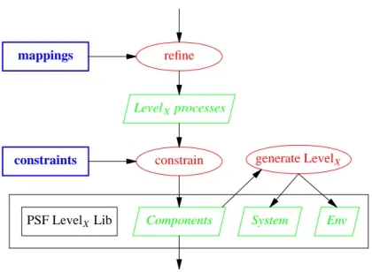
We can generalize the refine step in the PSF-ToolBus software engineering environment resulting in the workbench shown in Figure 9. The refine and constrain tools are general enough to work on the different level of the design. The generate LevelX tool and PSF LevelX Library can only be applied at level X . 4.2 A Process Algebra Software Engineering Workbench
So far, we used PSF as process algebra language with the workbenches. However, similar workbenches can be set up for variants of PSF or process algebra based languages similar to PSF. By generalizing from PSF we obtain a Process Algebra Software Engineering Workbench.
If this process algebra language can be translated to TIL, the intermediate language of the PSF Toolkit, the simulator and animation tools from the PSF Toolkit can be used. If another intermediate language (or the process algebra language itself) is used, then a simulator and animation tool for this intermediate language have to be dev eloped.
When using a different intermediate language, reuse of the simulator from the PSF Toolkit is possible. In the implementation of the simulator we only need to replace the kernel with a kernel for the intermediate language, thus reusing the design of the PSF simulator as presented in [11].
4.3 Forming an Environment
Several instances of the generalized workbench can be combined to form a software engineering environment. The instances can be connected in series. The specifications of the constraining processes can also be developed using instances of the generalized workbench, leading to an environment in which
PSF LevelX Lib Components System Env LevelX specification generate LevelX ... refine mappings LevelX processes constrain constraints ...
Figure 9. The PSF SE Workbench
the workbenches are connected in parallel as well as in series. 5. Related Work
In the literature several architecture description languages have been proposed and some are based on a process algebra, such as Wright [2], Darwin [21], and PADL [6]. A comparison of several ADL’s can be found in [25]. Most of the ADL’s do not have any or very little support for refinement. SADL [26][27] however, has been specially designed for supporting architecture refinement. In SADL, different levels of specifications are related by refinement mappings, but the only available tool is a checker. LOT OS [7], a specification language similar to PSF, is used in [19] for the formal description of architectural styles as LOTOS patterns, and in [34] it is used as an ADL for the specification of middleware behavior.
Formal development techniques such as B [1], VDM [17], and Z [9] provide refinement mechanisms, but they do not have support for architecture descriptions. Theπ-Method [28] has been built from scratch to support architecture-centric formal software engineering. It is based on the higher-order typedπ-calculus and mainly built around the architecture description languageπ-ADL [29] and the architecture refinement language π-ARL [30]. Tool support comes in the form of a visual modeler, animator, refiner, and code synthesiser.
To our knowledge there is no work done on generalizing software engineering workbenches and creating software engineering environment from instances of the generalized workbenches. There are many meta software development environments with which an environment can be created by integrating a set of existing tools. Such integration can easily be developed with the PSF-ToolBus software engineering environment as is shown in [12]. Here, an integrated development environment for PSF is created from the tools of the PSF Toolkit using the ToolBus to control the communication between the tools.
6. Conclusions
We hav e described the software engineering development process with PSF more formally by presenting the tools we use in the development process in a CASE setting. This resulted in an PSF-ToolBus software engineering environment consisting of two workbenches and a refine step. We generalized the refine step in the environment to an PSF software engineering workbench. Instances of this generalized workbench
can be combined to form a software engineering environment. We also generalized from the process algebra based language PSF to obtain a process algebra software engineering environment.
Using several levels for design of software systems has some advantages, of which the most important is that maintenance becomes easier. Adjustments and changes can be made at an appropriate abstract level of design and be worked down the lower levels. The influence of an adjustment or change on design decisions at the lower levels becomes clear in this process, and can be dealt with at the right abstract level. Also, the specifications are part of the documentation of the software system. Simulation of the specifications gives a good understanding of the design of the system, certainly in combination with animations generated from the specifications.
Another advantage is that not only parts of the implementation can be reused for other systems, but also the design can be reused. This is especially useful in an environment where similar products are being made or incorporated in other products.
Using workbenches in the engineering of software systems increases the advantages mentioned above, since it improves the understanding of the design process. It also gives the opportunity to reason about the design process in a more abstract setting.
A disadvantage is that the design process can be more work than strictly necessary for smaller software systems and for systems that are relatively easy to implement. However, software systems that are used over a long period of time need maintenance and evolve into larger and more complex systems. Reengineering the design of such systems is far more work than a durable design right from the start. References
[1] J.R. Abrial, The B-Book: Assigning Programs to Meanings, Cambridge University Press, 1996. [2] R. Allen and D. Garlan, ‘‘A Formal Basis for Architectural Connection,’’ ACM Transaction on
Software Engineering and Methodology, no. 6, pp. 213-249, 1997.
[3] J.A. Bergstra and J.W. Klop, ‘‘Process algebra: specification and verification in bisimulation semantics,’’ in Math. & Comp. Sci. II, ed. M. Hazewinkel, J.K. Lenstra, L.G.L.T. Meertens, CWI Monograph 4, pp. 61-94, North-Holland, Amsterdam, 1986.
[4] J.A. Bergstra, J. Heering, and P. Klint (eds.), ‘‘The Algebraic Specification Formalism ASF,’’ in Algebraic Specification, ACM Press Frontier Series, pp. 1-66, Addison-Wesley, 1989.
[5] J.A. Bergstra and P. Klint, ‘‘The discrete time ToolBus,’’ Science of Computer Programming, vol. 31, no. 2-3, pp. 205-229, July 1998.
[6] M. Bernardo, P. Ciancarini, and L. Donatiello, ‘‘Architecting Families of Software Systems with Process Algebras,’’ ACM Transactions on Software Engineering and Methodology, vol. 11, no. 4, pp. 386-426, 2002.
[7] T. Bolognesi and E. Brinksma, ‘‘Introduction to the ISO specification language LOTOS,’’ Computer Networks and ISDN Systems, vol. 14, pp. 25-59, 1987.
[8] L. Bouge and N. Francez, ‘‘A Compositional Approach to Superimposition,’’ in Proc. of the 14th ACM POPL’88, pp. 240-249, 1988.
[9] J. Davies and J. Woodcock, Using Z: Specification Refinement and Proof, International Series in Computer Science, Prentice Hall, 1996.
[10] B. Diertens, ‘‘Software (Re-)Engineering with PSF,’’ report PRG0505, Programming Research Group - University of Amsterdam, October 2005.
[11] B. Diertens, ‘‘Software (Re-)Engineering with PSF II: from architecture to implementation,’’ report PRG0609, Programming Research Group - University of Amsterdam, November 2006.
[12] B. Diertens, ‘‘Software (Re-)Engineering with PSF III: an IDE for PSF,’’ report PRG0708, Programming Research Group - University of Amsterdam, October 2007.
[13] B. Diertens, ‘‘New Features in PSF I - Interrupts, Disrupts, and Priorities,’’ report P9417, Programming Research Group - University of Amsterdam, June 1994.
[14] B. Diertens and A. Ponse, ‘‘New Features in PSF II - Iteration and Nesting,’’ report P9425, Programming Research Group - University of Amsterdam, October 1994.
[15] B. Diertens, ‘‘Simulation and Animation of Process Algebra Specifications,’’ report P9713, Programming Research Group - University of Amsterdam, September 1997.
[16] B. Diertens, ‘‘Generation of Animations for Simulation of Process Algebra Specifications,’’ report P2003, Programming Research Group - University of Amsterdam, September 2000.
[17] J. Fitzgerald and P. Larsen, Modelling Systems: Practical Tools and Techniques for Software Development, Cambridge University Press, 1998.
[18] A. Fuggetta, ‘‘A Classification of CASE Technology,’’ IEEE Computer, vol. 26, no. 12, pp. 25-38, 1993.
[19] M. Heisel and M. Levy, ‘‘Using LOTOS Patterns to Characterize Architectural Styles,’’ in Proc. of the 7th International Conference on Algebraic Methodology and Software Technology, LNCS, 1999. [20] A. Lopes and J.L. Fiadeiro, ‘‘Superposition: Composition vs Refinement of Non-deterministic,
Action-Based Systems,’’ Electronic Notes in Theoretical Computer Science, vol. 70, no. 3, pp. 352-366, 2002.
[21] J. Magee, N. Dulay, S. Eisenbach, and J. Kramer, ‘‘Specifying Distributed Software Architectures,’’ in Proc. of the 5th European Software Engineering Conf. (ESEC ’95), pp. 137-153, LNCS, 1995. [22] S. Mauw and G.J. Veltink, ‘‘A Process Specification Formalism,’’ in Fundamenta Informaticae XIII
(1990), pp. 85-139, IOS Press, 1990.
[23] S. Mauw and G.J. Veltink (eds.), Algebraic Specification of Communication Protocols, Cambridge Tracts in Theoretical Computer Science 36, Cambridge University Press, 1993.
[24] S. Mauw and G.J. Veltink, ‘‘A Tool Interface Language for PSF,’’ report P8912, Programming Research Group - University of Amsterdam, October 1989.
[25] N. Medvidovic and R. Taylor, ‘‘A Classification and Comparison Framework for Architecture Description Languages,’’ IEEE Transactions on Software Engineering, vol. 26, no. 1, pp. 70-93, 2000. [26] M. Moriconi, X. Qian, and R.A. Riemenschneider, ‘‘Correct Architecture Refinement,’’ IEEE
Tr ansactions on Software Engineering, vol. 21, no. 4, 1995.
[27] M. Moriconi and R.A. Riemenschneider, ‘‘Introduction to SADL 1.0: A Language for Specifying Software Architecture Hierarchies,’’ technical report SRICSL9701, Computer Science Laboratory -SRI international, March 1997.
[28] F. Oquendo, ‘‘π-Method: A Model-Driven Formal Method for Architecture-Centric Software Engineering,’’ ACM Software Engineering Notes, vol. 31, no. 3, 2006.
[29] F. Oquendo, ‘‘π-ADL: An Architecture Description Language based on the Higher Order Typed π-Calculus for Specifying Dynamic and Mobile Software Architectures,’’ ACM Software Engineering Notes, vol. 20, no. 3, 2004.
[30] F. Oquendo, ‘‘π-ARL: An Architecture Refinement Language for Formally Modelling the Stepwise Refinement of Software Architectures,’’ ACM Software Engineering Notes, vol. 29, no. 5, 2004. [31] J.K. Ousterhout, Tcl and the Tk Toolkit, Addison-Wesley, 1994.
[32] A. Rensink and R. Gorrieri, ‘‘Action Refinement,’’ in Handbook of Process Algebra, ed. J.A. Bergstra, A. Ponse, S.A. Smolka, pp. 1047-1147, Elsevier Science, 2001.
[33] A. Rensink and R. Gorrieri, ‘‘Vertical Implementation,’’ Information and Computation, vol. 170, no. 1, pp. 95-133, 2001.
[34] N.S. Rosa and P.R.F. Cunha, ‘‘A Software Architecture-Based Approach for Formalising Middleware Behaviour,’’ Electronic Notes in Theoretical Computer Science, vol. 108, pp. 39-51, 2004.