http://www.sciencepublishinggroup.com/j/fm doi: 10.11648/j.fm.20180402.11
ISSN: 2575-1808 (Print); ISSN: 2575-1816 (Online)
Effects of Rectangular Nozzle Arrangement Interval on
Characteristics of Multiple Rectangular Jets in a Line with
Constant Aspect Ratio
Shigetaka Fujita
1, *, Takashi Harima
1, Tsukuru Kunihiro
21Department of Mechanical and Electrical Engineering, National Institute of Technology Tokuyama College, Shunan, Japan 2
Hitachi Ltd., Kudamatsu, Japan
Email address:
*
Corresponding author
To cite this article:
Shigetaka Fujita, Takashi Harima, Tsukuru Kunihiro. Effects of Rectangular Nozzle Arrangement Interval on Characteristics of Multiple Rectangular Jets in a Line with Constant Aspect Ratio. Fluid Mechanics. Vol. 4, No. 2, 2018, pp. 38-47.
doi: 10.11648/j.fm.20180402.11
Received: May 14, 2018; Accepted: June 25, 2018; Published: July 26, 2018
Abstract:
The mean velocity field of turbulent free jet issuing from multiple rectangular nozzles (Rectangular nozzle aspect ratio L/d=12.5) with semicircular shaped end, which are arranged parallel to each other in a line, has been investigated, experimentally and systematically. The aim of this study is to examine characteristics of the mean velocity field of multiple rectangular jets and to clarify an effect of rectangular nozzle arrangement interval S/d (=25.00, 18.75, 12.50 and 6.25) on characteristics of both velocity and length scales in the mean velocity field, then to furnish a data of multiple rectangular jets in a line for the engineering design. Measurements were made using an X-array Hot-Wire Probe (5.0µm in diameter, 1.0mm effective length) and linearized constant temperature anemometers. Signals from the anemometers were passed through low-pass filters and sampled using an A/D converter. The processing of the signals was done by a personal computer. The acquisition time of the signals was from 60 to 120 seconds. The Reynolds number based on the nozzle width d and the exit mean velocity Ue (≅39 m/s) was kept constant at 25000, throughout this experiment. From this experiment, it was revealed that the potential core length of Uox/Ue on the x axis for all S/d cases existed until the section of x/d=7 which was the same with that of the single rectangular jet (Aspect Ratio: L/d=12.50) and the streamwise section indicating the two-dimensional jet decay (~(x/d)−0.5) moved toward the upstream region with the decreasing of S/d. The streamwise variation of the velocity scale Uox/Ue on the x axis showed the same decrease line with that of the two-dimensional jet from each downstream section, and also the length scale by/D2 on the long axisof rectangular nozzle indicated the same increase line with that of the two-dimensional jet from each downstream section, even if the rectangular nozzle arrangement interval S/d was different. Both of streamwise locations indicating the same decreasing characteristics of the velocity scale Uox/Ue on the x axis and the same increasing characteristics of the length scale by/d on the y axis with those of the two-dimensional jet, can be calculated approximately by two empirical formulas for any S/d case.
Keywords:
Multiple Rectangular Jets in a Line, Three-Dimensional Jet, Mean Velocity Field, Nozzle Arrangement Interval, Nozzle Aspect Ratio, Secondary Flow1. Introduction
The aim of this study is to examine the mean velocity field of multiple rectangular jets in a line and to clarify an effect of rectangular nozzle arrangement interval S/d (25.00, 18.75, 12.50 and 6.25) on characteristics of both velocity and length scales in the mean velocity field, then to furnish a data of multiple rectangular jets in a line for the engineering design. In
this study, the mean velocity field of turbulent free jet issuing from multiple rectangular nozzles with semicircular shaped end, which are arranged parallel to each other in a line, has been investigated, experimentally and systematically.
39 Shigetaka Fujita et al.: Effects of Rectangular Nozzle Arrangement Interval on Characteristics of Multiple Rectangular Jets in a Line with Constant Aspect Ratio
rectangular jets are also found in the promotion of the ventilating system in the big commercial and sports facilities and in the gas wiping used in the plating process of the steel belt [4], so it is realized that these kind of multiple jets are useful in many situations. However, to promote the efficiency of thrust augmentation, air ventilating systems and gas wiping, it is important to clarify an influence of the nozzle arrangement interval of multiple rectangular nozzles on developing characteristics of multiple rectangular jets.
So far, there were many studies about multiple rectangular jets [5-10]. Among these studies, Krothapalli, Baganoff and Karamacheti [5] (Rectangular nozzle length L=50.0mm, Rectangular nozzle width d=3.0mm, Rectangular nozzle arrangement interval S/d=8.0, Rectangular nozzle aspect ratio L/d=16.67, Rectangular nozzle interval aspect ratio S/L=0.48, Re=12000, Rectangular duct type) and Marsters [6] (L=38.0mm, d=3.96mm, L/d=9.6, S/d=4.7, S/L=0.49, Re=10000, Rectangular duct type) clarified the characteristics of the flowfield of multiple rectangular jets in a line to promote the mixing process. However, effects of variation in S/d and L/d on the developing characteristics of the multiple rectangular jets were not clarified.
On the other hand, Knystautas [11] (Nozzle diameter of the circular jet D=12.7mm, Nozzle arrangement interval S/D=1.5, 2.0, 3.0), and Pani and Dash [12] (D=6.35mm, S/D=3.0) reported the multiple circular jets in a line, theoretically and experimentally. But, it is difficult to suspect the characteristics of multiple rectangular jets in a line using the results of multiple circular jets in a line, because the developing characteristics of multiple circular jets in a line depend only on the circular nozzle arrangement interval S/D. However, the characteristics of multiple rectangular jets in a line are suspected to depend on both the nozzle arrangement interval S/d and the nozzle aspect ratio L/d.
From the mentioned above, an effect of rectangular nozzle arrangement interval S/d (=25.00, 18.75, 12.50 and 6.25) on the velocity and length scales will be investigated, experimentally and systematically in this study. Then, the asymptotic process of present multiple rectangular jets to the two-dimensional jet field will be discussed. Here, the nozzle aspect ratio L/d of rectangular nozzle used in the present multiple rectangular jets is 12.50, because the potential core length of single rectangular jet for L/d=12.50 takes a larger value due to the strong inward secondary flow on the long axis of the rectangular jet [13-15].
Furthermore, representative length scale D2 will be used in
discussing for the characteristics of both the velocity and length scales in the present multiple rectangular jets.
2. Experimental Setup and Procedure
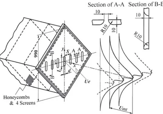
The configurations of the flowfield and the coordinate system used in this study are presented in Figure 1. The jet flow facility consists of a turbo fan, a settling chamber with a 990mm diagonal line, honeycomb and 4 mesh wire screens. The present three-dimensional jet nozzle which is made from an acrylic plate having a thickness of 10mm, is installed at the
end of the settling chamber. The shape of nozzle exit section is a quadrant circular as shown in Figure 1. The main axis length L and the width d of the rectangular nozzle are 125mm and 10mm (L/d=12.50), respectively. Four nozzle arrangement interval S/d used in this study were 25.00, 18.75, 12.50 and 6.25, respectively. The arrangements of multiple rectangular nozzles for all S/d cases, are presented in Figure 2.
Longitudinal mean velocity was measured using an X-array Hot-Wire Probe (dh=5.0µm in diameter, lh=1.0mm effective length: lh/dh=200) operated by the linearized constant temperature anemometers. Signals from the anemometers were passed through the low-pass filters (10 kHz) and sampled using A/D converter at 20 kHz. Processing of the signals was done by a personal computer. Acquisition time of the signals was from 60 to 120 seconds. The exit plane Reynolds number based on the nozzle width d and the exit mean velocity Ue which was measured at the rectangular nozzle exit centre (x/d=0, y/d=z/d=0), was kept constant at 25000 throughout the present experiment. Values of the rectangular nozzle exit turbulent intensity urms/Ue for all S/d cases were about 0.4×10⁻². In this experiment, an uncertainty associated with longitudinal mean velocity U is estimated at ±3% of Ue, which includes calibration errors of the linearized constant temperature anemometers.
3. Nomenclature
The nomenclatures used in this study are as follows. AD: Axisymmetric decay
ASD: Asymptotic decay
by: Half velocity width of the longitudinal mean velocity profile on the y axis
bz: Half velocity width of the longitudinal mean velocity profile on the z axis
CD: Characteristic decay
d: Nozzle width of the rectangular nozzle D: Nozzle diameter of the circular jet
D2: Representative length scale calculated from the total
nozzle outlet area of the present multiple rectangular nozzles as to be equal to the nozzle width of the two-dimensional jet
L: Nozzle long axis length of the rectangular nozzle MRJ: Multiple rectangular jets
S: Nozzle arrangement interval 2-DD: Two-dimensional decay Re: Reynolds number (=Ue⋅d/ν) U: Longitudinal mean velocity
Ue: Longitudinal mean velocity at the rectangular nozzle centre of the nozzle exit plane (x/d=0, y/d=z/d=0)
Uox: Longitudinal mean velocity on the x axis
x, y, z: Cartesian coordinate system with origin at the nozzle centre of the exit plane
Subscripts
e: Value at the rectangular nozzle centre of the nozzle exit plane (x/d=0, y/d=z/d=0)
m: Value at the middle location on the z axis between multiple rectangular nozzles
Figure 1. Configuration of the flowfield and the coordinate system.
Figure 2. Arrangement of multiple rectangular nozzles for all S/d cases.
4. Experimental Results and Discussion
4.1. Streamwise Variation of the Longitudinal Mean Velocity Profiles on both the y and z Axes
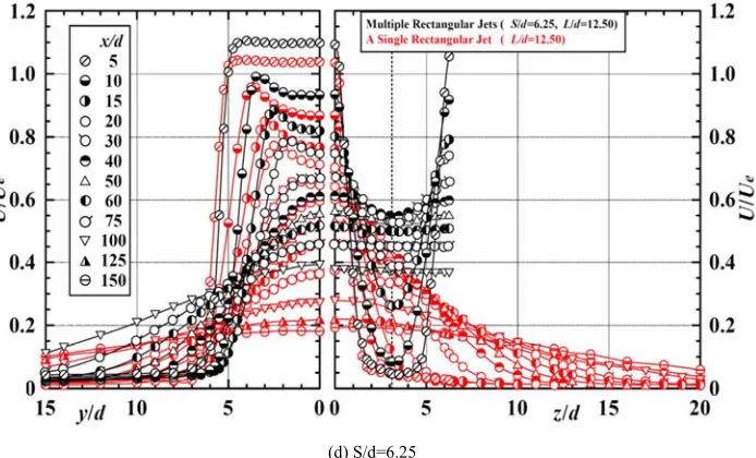
In this section, an effect of the variation of S/d on a shape of the longitudinal mean velocity profiles will be discussed. The streamwise variation of the longitudinal mean velocity profiles on both the y and z axes for the cases of S/d=25.00, 18.75, 12.50 and 6.25 are shown in Figures 3(a), (b), (c) and (d), respectively. A dotted line is drawn in the middle location between multiple rectangular nozzles on the right hand side for each S/d, and the profiles on both the y and z axes for the single rectangular jet (Red) [13] are plotted in all the figures for comparison.
At first, the result of single rectangular jet (Red) [13] will be discussed. The profiles of single rectangular jet on the y axis (long axis) in the region 5≤x/d≤30, show the saddle-back
shape [16-19] which takes the maximum value near the end of the long axis. The profiles on the y axis in the region of x/d≥40 decrease monotonically from the maximum value at the jet centre to zero value. On the other hand, all profiles on the z axis show a monotonous decrease from the maximum value at the jet centre to zero value.
41 Shigetaka Fujita et al.: Effects of Rectangular Nozzle Arrangement Interval on Characteristics of Multiple Rectangular Jets in a Line with Constant Aspect Ratio
(a) S/d=25.00
(b) S/d=18.75
(d) S/d=6.25
Figure 3. Streamwise variation of the longitudinal mean velocity profiles on both the y and z axes.
On the other hand, profiles on the z axis for the multiple rectangular jets show three distinct streamwise regions. The profiles in the first streamwise region show a monotonous decrease from the maximum value at the jet centre to zero value, and those in the second streamwise region show monotonous decrease from the maximum value at the jet centre to the minimum value at the middle location on the z axis between multiple rectangular nozzles, then those in the third streamwise region take each constant value of Uox/Ue along the z axis. In the first streamwise region, the extent of streamwise section of which the profiles show monotonous decrease to zero value, depends on S/d (x/d≤30 for S/d=25.00, x/d≤20 for S/d=18.75 and x/d≤15 for S/d=12.50). Here, for the case of S/d=6.25, the profile at the section of x/d=5 does not take the zero value at the middle location. The second streamwise region taking the minimum value at the middle location on the z axis between multiple rectangular nozzles, is found in the extent of 40≤x/d≤125 for S/d=25.00, 30≤x/d≤100 for S/d=18.75, 20≤x/d≤100 for S/d=12.50 and 5≤x/d≤60 for S/d=6.25, respectively. Then, the third region taking each constant value of Uox/Ue along the z axis, are shown in the region of x/d≥150 for S/d=25.00, x/d≥125 for S/d=18.75, x/d≥125 for S/d=12.50 and x/d≥75 for S/d=6.25, respectively.
In short, the streamwise section showing each constant value of Uox/Ue along the z axis, moves toward the upstream section with the decreasing of S/d.
4.2. Streamwise Variation of Velocity Scale
In this section, a decay tendency of each velocity scale for the present multiple rectangular jets caused by the variation of S/d, will be discussed. Figure 4 shows the streamwise variation of both the velocity scales Uox/Ue on the x axis and Um/Ue at the middle location on the z axis between the multiple rectangular nozzles. The results of the single rectangular jet (Red) [13], the two-dimensional jet by authors (Light blue) and the multiple rectangular jets by Krothapalli et al. (Green) [5] and Marsters (Blue) [6], are plotted for
comparison. Here, the result of the two-dimensional jet was obtained from the preliminary experiment in author’s laboratory.
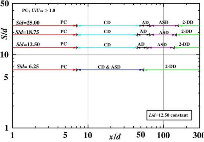
At first, a potential core region (PC region) of Uox/Ue≥1.0 for the single rectangular jet exists until the section of x/d=7. The velocity scale Uox/Ue in the region of 7<x/d<50 shows a characteristic decay region (CD region) [6]. Furthermore, Uox/Ue in the region of x/d≥50 decreases in proportion to (x/d)−0.5 which is the same decay rate with that of the two-dimensional jet and this region will be called a two dimensional jet decay region (2-DD region).
On the other hand, the potential core region for all S/d cases (=25.00, 18.75, 12.50 and 6.25) also exist until the section of x/d=7 same as that of the single rectangular jet. After the PC region, extent of CD region for S/d=25.00, 18.75 and 12.50 is 7<x/d<50, 7<x/d<45 and 7<x/d<45, respectively. Furthermore, the extent of an axisymmetric decay region (AD region) [6] in which Uox/Ue decreases in proportion to (x/d) −1.0 for S/d=25.00, 18.75 and 12.50 is 50≤x/d≤65, 45≤x/d≤65 and 45≤x/d≤60, respectively. Then, Uox/Ue experiences an asymptotic decay region (ASD region) before approaching to the 2-DD region in which Uox/Ue decreases in proportion to (x/d) −0.5. Finally, the 2-DD region for S/d=25.00, 18.75 and 12.50 is x/d≥160, x/d≥150 and x/d≥140, respectively. However, for the case of S/d=6.25, Uox/Ue does not indicate the AD region, but shows CD & ASD region in the region of 7<x/d<55, then Uox/Ue shows 2-DD region in the region of x/d≥55. Comparing the present results with those of Krothapalli et al. [5] and Marsters [6], it can be concluded that the length of potential core regions for all the present S/d cases are extended compared with those of them.
43 Shigetaka Fujita et al.: Effects of Rectangular Nozzle Arrangement Interval on Characteristics of Multiple Rectangular Jets in a Line with Constant Aspect Ratio
Figure 4. Streamwise variation of both the velocity scales Uox/Ue on the x axis and Um/Ue at the middle location on the z axis between the multiple rectangular nozzles normalized by nozzle width d.
4.3. Streamwise Variation of Length Scale
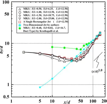
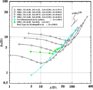
To investigate an effect of variation of S/d on the length scale in the multiple rectangular jets in a line, the streamwise variation of the half-velocity width on the y axis is shown in Figure 6. The results of the single rectangular jet (Red) [13], two-dimensional jet by authors (Light blue) and the multiple rectangular jets by Krothapalli (Green) [5] are plotted for comparison.
The profile of half-velocity width on the y axis for the single rectangular jet decreases monotonically from the section of x/d=5 and takes the minimum value at x/d=40. Then, by/d increases and approaches to the increasing rate of (x/d)1.0.
While, by/d on the y axis for all S/d cases of 25.00, 18.75, 12.50 and 6.25, take each minimum value at each section of x/d=40, 40, 30 and 20, respectively. Additionally, the magnitude of these minimum values for all S/d cases are smaller than that of the single rectangular jet. Comparing the present results of by/d with that of the multiple rectangular jets by Krothapalli et al. [5], the present values are very smaller than that of Krothapalli et al. After that region, the value of each by/d for all S/d cases increases with an increasing rate larger than (x/d)1.0 and finally approaches to the increasing rate of (x/d)1.0 of the two-dimensional jet. The sections at which by/d takes almost the same increasing rate with that of the
two-dimensional jet, are x/d>150, x/d≥150, x/d≥125 and x/d≥100, for S/d=25.00, 18.75, 12.50 and 6.25, respectively.
From the results mentioned above, it is clarified that the half-velocity width by/d on the y axis for all S/d cases take each minimum value at each upstream location, and the locations move towards the upstream region with the decreasing of S/d. Therefore, the restraint effect to the development of half velocity width by/d in the upstream region, can be operated by a variation of nozzle arrangement interval S/d.
4.4. Streamwise Variation of Velocity and Length Scales
Normalized by the Representative Length Scale D2
Figures 7 and 8 show the streamwise variation of velocity and length scales normalized by each representative length scale D2 for S/d=25.00 (D2=1.97d), 18.75 (D2=0.98d), 12.50
(D2=0.66d) and 6.25 (D2=0.49d), respectively. The results of
the two-dimensional jet by authors (Light Blue) and the multiple rectangular jets by Krothapalli et al. (Green) [5] and Marsters (Blue) [6] are plotted for comparison.
The potential core length for each S/d case normalized by D2 shows larger value with the increasing of S/d. After the PC
region, the values of Uox/Ue decrease monotonically for all S/d cases. Furthermore, decay rate of Uox/Ue for the cases of
45 Shigetaka Fujita et al.: Effects of Rectangular Nozzle Arrangement Interval on Characteristics of Multiple Rectangular Jets in a Line with Constant Aspect Ratio
Figure 7. Streamwise variation of velocity scales on the x axis renormalized by representative length scale D2.
Figure 9. The streamwise locations of both the velocity scale and the length scale normalized by representative length scale D2 for all S/d cases (S/d=25.00, 18.75, 12.50 and 6.25) at which the velocity scale Uox/Ue on the x axis decreases in proportion to the decay rate of the two-dimensional jet (∝(x/d)−0.5) and at which the length scale by/d on the y axis increases in proportion to the increasing rate of the two-dimensional jet (∝(x/d)1.0).
S/d=25.00, 18.75 and 12.50, change in the middle streamwise location at which Uox/Ue takes each value between 0.5 and 0.7. Then each curve for S/d=25.00, 18.75 and 12.50 approaches to that of the two-dimensional jet and coincides with it from each streamwise location, and finally they decrease as (x/d)−0.5 in the region of x/D2>325.9, 229.0 and
142.4, respectively. While, the decrease curve of S/d=6.25 coincides with that of the two-dimensional jet in the region of x/D2≥28.0.
In concluding as mentioned above, if the streamwise distance x is normalized by the representative length scale D2,
the streamwise variation of velocity scale Uox/Ue on the x axis shows the same decreasing line with that of the two-dimensional jet from each downstream section, even if the nozzle arrangement interval S/d is different. Therefore, it may be inferred that the decay process of velocity scale Uox/Ue for any S/d case of L/d=12.50 can be supposed approximately from Figure 7.
On the other hand, the half velocity width by/D2 on the long
axis for each S/d case in Figure 8, decreases monotonically in the upstream region and takes the minimum value at each section. Then each value of by/D2 increases, and finally the
increasing rate of by/D2 coincides with that of the
two-dimensional jet (∝(x/d) 1.0) from each streamwise location. The streamwise locations taking almost the same values of by/D2 with that of the two-dimensional jet, are x/D2=305.5,
229.0, 127.2 and 50.9 for S/d=25.00, 18.75, 12.50 and 6.25, respectively.
From the results mentioned above, if the streamwise distance x is normalized by the representative length scale D2,
it is clarified that the length scale by/D2 on the y axis shows the
same increasing line with that of the two-dimensional jet from each streamwise location, even if the nozzle arrangement interval S/d was different.
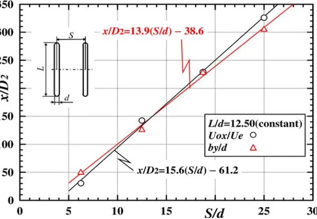
4.5. Streamwise Locations Showing the Characteristics of the Two-Dimensional Jet
Figure 9 shows the both streamwise locations at which the velocity scale Uox/Ue on the x axis decreases in proportion to the decay rate of (x/d)−0.5 and at which the length scale by/d on the long axis increases in proportion to the increasing rate of (x/d)1.0. Here, the data of streamwise distances x/D2 for all S/d
cases shown in Figures 7 and 8, were used to derive empirical formulas.
Using these results, the following empirical formulas (1) and (2) can be derived.
Uox/Ue: x/D2 = 15.6 × (S/d) − 61.2 (1)
and
by/d : x/D2 = 13.9 × (S/d) − 38.6 (2)
From these formulas, both of the streamwise locations indicating the same decreasing characteristics of the velocity scale Uox/Ue on the x axis and the same increasing characteristics of the length scale by/d on the long axis with those of the two-dimensional jet, can be calculated, approximately.
5. Conclusion
The mean velocity field of turbulent free jet issuing from multiple rectangular nozzles in a line, which are arranged parallel to each other, has been investigated, experimentally and systematically. The results obtained are as follows:
47 Shigetaka Fujita et al.: Effects of Rectangular Nozzle Arrangement Interval on Characteristics of Multiple Rectangular Jets in a Line with Constant Aspect Ratio
rectangular jet. Furthermore, the streamwise extents of CD, AD, ASD and 2-DD regions for all S/d cases, are clarified.
(2)The half velocity width by/d on the y axis for all S/d cases take each minimum value at each upstream location, and the locations move towards the upstream region with the decreasing of S/d. Therefore, the restraint effect to the development of the half velocity width by/d in the upstream region can be operated by a variation of nozzle arrangement interval S/d.
(3)If the streamwise distance x is normalized by the representative length scale D2, the streamwise variation
of the velocity scale Uox/Ue on the x axis shows the same decreasing line with that of the two-dimensional jet from each downstream location, and also the length scale by/D2 on the y axis shows the same increasing line
with that of the two-dimensional jet from each streamwise location, even if the nozzle arrangement interval S/d was different.
(4)Both of the streamwise locations indicating the same decreasing characteristics of the velocity scale Uox/Ue on the x axis and the same increasing characteristics of the length scale by/d on the y axis with those of the two-dimensional jet, can be calculated approximately by the empirical formulas (1) and (2) for any S/d case, respectively.
References
[1] Lilley, G. M., Aerodynamic noise – a review of the contributions to jet noise research at the College of Aeronautics, Cranfield 1949-1961 (together with some recent conclusions), Aeronautical Journal, Vol. 88, No. 875, pp. 213-223, 1984. [2] Bevilaqua, P. M., Evaluation of hyper mixing for thrust
augmenting ejectors, Journal of Aircraft, Vol. 11, No. 6, pp. 348-354, 1974.
[3] Lummus, J. R., Criticality of engine exhaust simulations on VSTOL model-measured ground effects, Journal of Aircraft, Vol. 18, No. 4, pp. 245-251, 1981.
[4] Yu, S., Japanese patent disclosure 2003-268523 (2003) (in Japanese).
[5] Krothapalli, A., Baganoff, D. and Karamcheti, K., Development and structure of a rectangular jet in a multiple jet configuration, AIAA Journal, Vol. 18, No. 8, pp. 945-950, 1980.
[6] Marsters, G. F., Measurements in the flowfield of a linear array of rectangular jets, AIAA Journal, Vol. 17, No. 11, pp. 774-780, 1980.
[7] Krothapalli, A., Baganoff, D. and Karamcheti, K., Partially confined multiple jet mixing, AIAA Journal, Vol.19, No.3, pp.324-328, 1980.
[8] Mostafa, A. A., Khalifa, M. M. and Shabana, E. A., Experimental and numerical investigation of multiple rectangular jets, Experimental Thermal and Fluid Science, Vol. 21, pp. 171-178, 2000.
[9] Li, H., Anand, N. K. and Hassan, Y. A., Computational study of turbulent flow interaction between twin rectangular jets, International Journal of Heat and Mass Transfer, Vol. 119, pp. 752-767, 2018.
[10] Meyer, M. t., Mudawar, I., Boyack, C. E. and Hale, C. A., Single-phase and two-phase cooling with an array of rectangular jets, International Journal of Heat and Mass Transfer, Vol. 49, pp. 17-29, 2006.
[11] Knystautas, R., The turbulent jet from a series of holes in line, Aeronautical Quarterly, Vol. 15, pp. 1-28, 1964.
[12] Pani, B. and Dash, R., Three-dimensional single and multiple free jets, Journal of Hydraulic Engineering, Vol. 109, No. 2, pp. 254-269, 1983.
[13] Fujita, S., Harima, T. and Osaka, H., Turbulent jets issuing from rectangular nozzles with a rectangular notch at the midspan, Fluid Structure Interaction V, pp. 61-70, 2009. [14] Quinn, W. R. and Militzer, J, Experimental and numerical study
of a turbulent free square jet, Physics of Fluids, Vol. 31, No. 5, pp. 1017-1025, 1988.
[15] Quinn, W., On mixing in an elliptic turbulent free jet, Physics of Fluids, Vol. 1, No. 10, pp. 1716-1722, 1989.
[16] Marsters, G, F. and Fotheringham, J., The influence of aspect ratio on incompressible turbulent flows from rectangular slots, Aeronautical Quarterly, Vol. 31, Part 4. pp. 285-305, 1980. [17] Krothapalli, A., Baganoff, D. and Karamcheti, K., On the
mixing of a rectangular jet, Journal of Fluid Mechanics, Vol. 107, pp. 201-220, 1981.
[18] Quinn, W, R., Passive near-field mixing enhancement in rectangular jet flows, AIAA Journal, Vol. 29, N0. 4, pp. 515-519, 1991.