doi:10.1155/2007/87646
Research Article
An Omnidirectional Stereo Vision-Based Smart Wheelchair
Yutaka Satoh and Katsuhiko Sakaue
Information Technology Research Institute, National Institute of Advanced Industrial Science and Technology (AIST), Central 2, Umezono 1-1-1, Tsukuba, Ibaraki 305-8568, Japan
Received 31 December 2006; Accepted 23 May 2007
Recommended by Dimitrios Tzovaras
To support safe self-movement of the disabled and the aged, we developed an electric wheelchair that realizes the functions of detecting both the potential hazards in a moving environment and the postures and gestures of a user by equipping an electric wheelchair with the stereo omnidirectional system (SOS), which is capable of acquiring omnidirectional color image sequences and range data simultaneously in real time. The first half of this paper introduces the SOS and the basic technology behind it. To use the multicamera system SOS on an electric wheelchair, we developed an image synthesizing method of high speed and high quality and the method of recovering SOS attitude changes by using attitude sensors is also introduced. This method allows the SOS to be used without being affected by the mounting attitude of the SOS. The second half of this paper introduces the prototype electric wheelchair actually manufactured and experiments conducted using the prototype. The usability of the electric wheelchair is also discussed.
Copyright © 2007 Y. Satoh and K. Sakaue. This is an open access article distributed under the Creative Commons Attribution License, which permits unrestricted use, distribution, and reproduction in any medium, provided the original work is properly cited.
1. INTRODUCTION
The purpose of this work is to enhance the abilities of the disabled and the aged and to support their self-movement by smart electric wheelchairs. An electric wheelchair is a device used to compensate for the physical ability of a person who experiences difficulty walking unassisted. Also, since the aged and the disabled often have decreased sens-ing and judgment abilities, it is often important to as-sist these abilities as well as their physical abilities. Even a person with normal sensory and judgmental abilities may not be able to check circumferential safety adequately because an electric wheelchair can change its direction quickly, make a free turn, and move in the reverse direc-tion. Therefore, there are great needs for preventing the great risks of collision, differences in surface levels, and so on.
In the automotive field, intelligent systems to predict the potential hazard of a collision and apply braking au-tomatically have already been developed and put to prac-tical use [1]. As mentioned before, these functions are extremely important even for electric wheelchairs. Com-pared with the automotive field, the market scale is small but the needs may be even greater [2, 3]. Unlike an au-tomobile, an electric wheelchair is used in various living
spaces, including crowds. This necessitates the introduction of technology to sense an ambient environment more posi-tively.
Therefore, we developed a smart electric wheelchair equipped with stereo omnidirectional system (hereinafter, the SOS). The SOS has the ability of acquiring high-resolution color images and range data in real time in all di-rections. By using this ability, we realized various user sup-port functions: (1) a function to detect potential hazards in a moving environment, (2) a function to recognize the user gestures and riding posture, and (3) a function to distribute omnidirectional color image sequences to remote locations via a wireless network.
Figure1: The appearance of the prototype.
distribution of omnidirectional color image sequences to re-mote locations.
Several past proposals have used the hyperbolical omni-directional camera system or the fisheye camera system to realize similar functions [9–11]. However, the SOS has sev-eral advantages: (1) spatial information can be acquired uni-formly with high resolution because the system consists of multiple cameras, (2) the system has a spherical field of view with no blind spots in any direction, and (3) range data can be acquired in real time with color images. Because of these advantages, our proposed system has greater performance than that of conventional systems.
2. SYSTEM STRUCTURE
2.1. Outline of prototype
Figure 1shows the appearance of the prototype. The SOS is installed diagonally in front of the head of the user. This po-sition has the following features: (1) the environment around the electric wheelchair can be observed in a wide range, (2) the user can get in and out easily and without great dis-turbance, (3) enough clearance is secured in ordinary living spaces because the position is about the height of a person (150 cm from the floor). Since our living spaces are natu-rally designed for a person to recognize potential hazards when walking, the position close to the eye height of a person walking is rational for the recognition of potential hazards in moving environments.
Figure 2 shows the block diagram of the system. The SOS and electric wheelchair are controlled in an integrated form by a small PC (Figure 3: Pentium D 3.2 GHz, Windows XP) mounted behind the seat. Since power is supplied from the mounted battery (shared between the PC and electric wheelchair), the system requires no external cable and can operate independently for about three hours.
The system also has functions to browse omnidirectional image sequences from a remote location by a wireless LAN. If the wireless LAN now used is replaced with a high-speed mo-bile phone line or another similar device, the system can be
monitored and supported from a remote place. In addition, viewing distributed omnidirectional color image sequences through an immersive visualization system may be able to produce a telepresence effect [12], as if the viewer was at-tending the user.
2.2. Stereo omnidirectional system (SOS)
The SOS (Figure 4) is an innovative camera system devel-oped by the authors of [13,14]. Despite the fist-size compact structure 11.6 cm in diameter and 615 g in weight, the system can acquire omnidirectional color images and range data of high resolution in real time with no blind spots.Table 1lists the main SOS specifications. The SOS has the basic shape of a regular dodecahedron with trinocular stereo camera units on each face (36 cameras total). To ensure the accuracy of the range data, it is necessary to secure an appropriate intercam-era distance (a stereo baseline) of the stereo camintercam-era units. In this system, for measuring objects in a target range of about 3 to 4 meters around the electric wheelchair, a stereo baseline of 50 mm is allocated.
The cameras on each stereo camera unit are on the same plane and their optical axes are parallel with each other. The center camera is placed at right angles to the other two cam-eras so that their 50-mm stereo baselines intersect at the cen-ter camera. Thus, each pair of scen-tereo camera units can satisfy both the horizontal and vertical epipolar constraints, and the corresponding point search costs can be reduced. Stereo cal-ibration is performed for each stereo camera unit, and the-influences of lens distortion and the misalignment between cameras are eliminated by software. And then, calibrations are performed among the stereo camera units. For these cal-ibrations, a known pattern needs to be presented to all stereo camera units at the same time. Therefore, we manufactured a calibration box of one cubic meter. AsFigure 5shows, the SOS is first placed at the bottom of the box. Then the bottom is covered with the main body (In the figure, it is placed next to the bottom.). In other words, the SOS is placed inside the box. The box is made of semitransparent acrylic resin so that lighting from the outside can reserve enough illuminance in-side for shooting.
It is a problem that the size of the camera head becomes excessively large when the stereo camera units are arranged in a dodecahedron shape. To address this problem, we have mounted the three cameras of each stereo camera unit on a T-shaped arm (see Figure 6), so that the base planes of the stereo camera units intersect each other. This reduces the camera head size while keeping the stereo baseline length.
Figure 7 shows images captured by the stereo camera unit. Each camera acquires intensity information (8 bits) of the VGA size (640×480 pixels) for disparity calculation. In addition, the center camera acquires color information.
Stereo omnidirectional
system
Joystick
USB
RS232C
Control PC Image/control client Wheelchair
control unit
PCI-express
×4
Main memory /CPU
Optical link (1.2 Gbps×2)
Wireless LAN
Me
m
o
ry
unit
Sy
st
em
co
n
tro
l
unit
(PCI
car
d
)
Figure2: Block diagram of the system.
Figure3: Onboard PC.
Figure4: Stereo omnidirectional system (SOS).
Figure5: A calibration box.
3. HIGH-SPEED AND HIGH-QUALITY PANORAMIC IMAGE GENERATION
In this study, the electric wheelchair moving speed is as-sumed to be about 2 to 3 km/h. For potential hazard de-tection with no delay, a high frame rate is necessary. Mean-while, images distributed outside for remote monitoring re-quire high quality for the feeling of presence. We discuss a method of satisfying these conflicting requirements.
Mount center
Center camera
19.6 30.4 50 50 32 . 6 17 . 4 (a) (b)
Figure6: Trinocular stereo camera unit.
Table1: The main SOS specifications.
Basic shape dodecahedron
Image sensor 1/4CMOS image sensor
Resolutions of individual cameras 640 (H)×480 (V) pixels Focal length of individual cameras 1.9 mm
FOV of individual cameras 101 deg. (H)×76 deg. (V) Stereo base line length 50 mm
Frame rate 15 fps
Diameter of camera head 11.6 cm
Weight 600 g
Power consumption 9 W (15 V, 0.6 A)
First, it is assumed that the SOS has been calibrated and a global coordinate system with the system center (camera head center) as the origin is defined (in other words, the in-ternal and exin-ternal parameters of each camera are known). It is also assumed that the lens distortion of each camera has been rectified and input images after rectification will be handled. Since the SOS covers a spherical field of view with 12 cameras, image synthesis can be considered as a problem of splitting a spherical field.
LetSbe the sphere of radiusrin a coordinate system with the origin at the center of the SOS (seeFigure 9). Each vector
ponSdefines a camera set,
Cp⊆ {1, 2,. . ., 12}, (1) of which each member camera has p in the field of view (FOV). Once (nonempty) Cp is given, the optimal camera cto observepis decided by the condition
p•nc=maxp•nc|c∈Cp. (2)
Note that this condition is designed to choose the best camera to observepnear the center of the FOV.
Actual panoramic image synthesis is considered. The ho-mogenous coordinates (x,y,z, 1)T of point p on sphere S, corresponding to arbitrary pointq=(i,j) on the finally syn-thesized panoramic image (Mercator projection)QofM×N pixels, can be expressed as follows:
⎛ ⎜ ⎜ ⎜ ⎝ x y z 1 ⎞ ⎟ ⎟ ⎟ ⎠= ⎛ ⎜ ⎜ ⎜ ⎝
−cos(b) cos(a)•r cos(b) cos(a)•r
−sin(b)•r 1
⎞ ⎟ ⎟ ⎟
⎠, (3)
wherea andb correspond to the longitude and latitude as follows:
a= 2Mjπ,
b= (2i−N)π
2N .
(4)
Let us say we want to know the location (e.g.,w) ofp
in the camera-coordinate system for a camerac, assumingp
is included in the FOV of the camera c. The locationw = (u,v, 0, 1)Tin camera imageWccan be calculated as follows:
w=AcRctcp, (5)
whereAcis the matrix of internal parameters and [Rctc] is the matrix of external parameters, both for camerac. The size of the image of cameracdetermines whether ifwis actually in Wc. If not, we conclude thatw ∈/ Wc, which meansc /∈Cp. In other words, cameracis not the appropriate camera to observe the point p. Starting from {1,. . ., 12}, the iterated removal of inappropriate camera gives usCp.
In the ideal design of the SOS, the camera wherep be-longs may be selected as follows:
p•nc=maxp•nc|1≤c≤12. (6)
However, the image center of the cameras used in the SOS may deviate from the physical design center. (This is not a logical problem because the internal parameters are known.) In such a case, the selected camera may be unable to cover the pointp. The above-mentioned method enables us to choose another camera to cover pointp, since the SOS has overlap-ping regions near the boundaries between constituent cam-eras.
As described above, we can construct the mappingF : Q→W1∪ · · · ∪W12, so that eachqinQcorresponds to the
pointwin the optimal camera.Figure 10shows a panoramic image which shows a result of the sphere division. The num-bered regions in the figure show that each regioncbelongs to camerac. The mappingF depends only on the geomet-ric design of the SOS and the parameters of the constituent cameras. Therefore, the mappingF can be implemented as a lookup table, which enables high-speed rendering of the panoramic image.
The above functions enable us to generate a panoramic image of 512×256 pixels on a PC of 3.6-GHz CPU within 10 milliseconds. Figure 11 shows a panoramic image (r = 1.5 m) generated from the actual images.Figure 12shows im-ages of the spherical mapping using OpenGL.
4. IMAGE GENERATION INDEPENDENT OF THE CAMERA ATTITUDE
Since the SOS has a spherical field of view, even an arbitrary rotation of a camera can be completely recovered.
4.1. Estimation of camera attitude
(a) Top camera (b) Disparity image
(c) Center camera (d) Right camera
Figure7: An example of images captured by a stereo camera unit.
Data transfer unit
Data transfer unit
Elect
ro
o
ptical
unit
Data (1 Gbps) Control &
sync Optical link 1.2 Gbps×2 Data (1 Gbps)
Camera head
(stereo camera unit×12) Control PC 64-bit PCI bus Main memory /CPU
M
emor
y
unit
Sy
st
em
co
n
tro
l
unit
(PCI
car
d
)
Figure8: The SOS system configuration.
inFigure 1. Since the height and angle of the SOS arm can be adjusted according to the user, the attitude of the SOS changes arbitrarily. To detect the mounting attitude, there-fore, attitude sensors were attached (seeFigure 13). When the electric wheelchair is not moving, the direction of grav-ity (vertical direction) is detected by the acceleration sensor to determine the SOS attitude.Figure 14shows an example after the recovery of rotation using the attitude parameters actually acquired by the acceleration sensor. The upper stage of the figure is before recovery (the camera support pole di-rection is thez-axis) and the lower stage is after recovery (the vertical direction detected by the sensor is the z-axis). It is clear that, after recovery, the effect of the camera rotation has been cancelled.
Panoramic coordinate system
Thecth camera
SphereS
X
Y
Z
nc P q
w
Q M
N
W m
n
r
Thecth camera coordinate system
Figure 9: Relationship between individual cameras and a
pano-ramic coordinate system.
Figure10: A panoramic image which shows the sphere division.
Figure11: An example of a panoramic image generated from the
actual images.
based on fixed attitude parameters enables the high-speed in-tegration of individual camera images into omnidirectional panoramic images, as mentioned in Section 3. If the atti-tudechanges, however, this kind of conversion table cannot be prepared because the attitude parameters are unknown. This necessitates extremely costly geometric conversion processing for each frame. To solve this problem, we used the method explained next.
4.2. High-speed recovery of arbitrary rotation
The method described here enables the recovery of arbitrary rotation by only table lookup and C/C++ memory pointer
(a) (b)
Figure12: Spherical mapping images.
Acceleration sensor Gyro-sensor
Figure13: Attitude sensors.
(a)
(b)
Figure14: An example of a rotation-corrected image. An original
image (a) and a corrected image (b).
R=RZ(γ)RY(β)RX(α)
Z
γ
Y
β
X α
Cylindrical image developed around z-axis
γ
Cylindrical image developed around y-axis
β
Cylindrical image developed around x-axis
α
Camera 1 Camera 2 Cameran
(i,j) Camera 12
Figure15: High-speed generation of rotation-corrected image.
three-axis angular coordinate system (A,B,Γ), a spherical image with no rotation change can be obtained as (A−α, B−β,Γ−γ). Judging from this relationship, the volumes of rotation around thex-,y-, andz-axes correspond to the horizontal image shift in the panoramic image developed on each axis. (This shift is possible by a memory pointer manip-ulation only.) By using this property, the rotation is recovered at high speed, as explained next.
The correspondence between a panoramic image (θx,φx) developed on the x-axis and individual camera images is calculated first. These correspondence relations are created by planar projection between the camera coordinate system and the global coordinate system of the SOS, and are rep-resented as cx(θx,φx),ix(θx,φx), and jx(θx,φx). Here, cx is the camera number andix andjxare the coordinates of an image from cameracx. Then, the relationship between the panoramicimages (θy,φy) and (θx,φx) developed on theY -axis andx-axis, respectively, is calculated and represented by xθ(θy,φy) andxφ(θy,φy). Likewise, the relationship between the panoramic image (θz,φz) developed on thez-axis and the panoramic image (θy,φy) developed on they-axis are repre-sented byyθ(θz,φz) andyφ(θz,φz), respectively. By using the SOS attitude parameters (α,β,γ), the relationship between the rotation-recovered panoramic image and the individual camera images can be obtained from the above relationships by multiple indexing. The following is the formula for the relationship with camera numbercr(θ,φ):
cyθy,φy=cxxθθy,φy−α,xφθy,φy,
czθz,φz=cyyθθz,φz−β,xφθz,φz,
cr(θ,φ)=cz(θ−γ,φ).
(7)
In the same way as for the above formula, multiplex in-dex tables can be built forir(θ,φ) and jr(θ,φ) as well.
Us-Figure16: An example of an omnidirectional depth image
(bot-tom). The higher the brightness of the pixels, the shorter the range.
ing the above method, a PC of 3.6-GHz CPU can generate a rotation-recovered image in about 15 milliseconds.
5. DETECTION OF POTENTIAL HAZARDS IN MOVING ENVIRONMENTS
To support safe movement, potential hazards are detected during movement and braking is assisted. The potential hazards to be detected are as follows: (1) collision against a pedestrian, wall, desk, or other object, (2) a level difference or stairs, and (3) a rope or beam in the air.
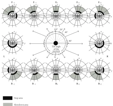
F−2 F−1 F0 F+1 F+2
Tilt angle of the joystick
L R
0◦ 20◦ 40◦
80◦
B−2 B−1 B0 B+1 B+2
x x x x x
y y y y y
x x
y y
x x x x x
y y y y y
Stop area
Slowdown area
Figure17: Mask patterns for limiting the obstacle detection area.
A detected potential hazard factor actually disturbs the electric wheelchair, depending on the direction of move-ment. AsFigure 17 shows, mask patterns that change with the input direction of the joystick are set to limit the de-tection area. In the figure,Fn represents the forward
direc-tion, Bn represents the backward direction, and L and R
represent in situ rotation. Each pattern shows the electric wheelchair viewed from above (z-axis direction). With the floor height asz = 0, the range of detection along the z -axis is−0.5 m< z <1.6 m. Therefore, the detection area is cylindrical. To prevent fine floor irregularities or measure-ment errors from stopping the electric wheelchair frequently, the range of−0.05 m < z < 0.05 m is excluded from the detection area (the prototype electric wheelchair is capable of traversing a 10-cm level difference without problem). For straight forward and backward runs (F0 andB0), a square
area is set to allow passing through a narrow aisle. For other areas (turns), a sector area is set by considering probabilistic expansion because the volume of the turn is always changed by user operation.
The electric wheelchair slows down if any object is de-tected in the slowdown area and stops completely if any
ob-ject is detected in the stop area. More specifically, if the num-ber of 3D points observed at a position higher than the floor area (0.05 m < z <1.6 m) in each detection area exceeds a threshold, the electric wheelchair slows down or stops. The threshold is set to eliminate the influences of noises and ob-servation errors, and its value is determined experimentally. By testing under various environmental conditions, we veri-fied that up to about 80 false positives could be detected. For this experiment, therefore, the threshold was set to 100 in all areas.
Since the detection range includes an area lower than the floor (−0.5 m < z < −0.05 m), the system can even detect stairs going down and stops the electric wheelchair, as shown inFigure 18.Figure 19shows the transition of the number of 3D points in theF0 area in the case ofFigure 18. The
hor-izontal axis indicates the wheelchair position (beginning of the stairs: 0) and the horizontal axis indicates the number of 3D points.
Stop
Figure18: Potential hazard detection.
0 100 200 300 400 500 600 700
N
u
mber
of
3D
points
−2.0 −1.5 −1 −0.5 0
Wheelchair position (m)
Figure19: Transition of the number of 3D points.
as general rules. As the results of orbital simulation and sev-eral tests using sevsev-eral kinds of electric wheelchairs, we veri-fied that the rules shown inFigure 17are applicable in many cases.
For evaluating the usability of the potential hazard detec-tion funcdetec-tion, three users performed run tests for more than a month using the prototype. This clarified several advan-tages and limitations. First, regarding the potential hazard detection performance, the evaluation was generally good. For an object such as a table, as an example, the conventional ultrasonic or infrared sensors of limited detection areas suc-cessfully detected the legs of the table but not the tabletop. This detection failure caused a collision in some cases, since the SOS has no dead angle in the detection area and stops the electric wheelchair safely even in this type of case. For an ob-ject of poor texture, such as a wall having a wide area painted evenly white, the reliability of range data by stereo measure-ment has become low, and false negatives have occurred par-tially. This system, however, has only a small possibility of
Gesture detection area
Collision detection area
Figure20: Gesture detection area.
collision because it reduces the speed or stops if any object in the detection area is detected even partially.
6. GESTURE/POSTURE DETECTION
Emergency stop
Figure21: A case of an emergency stop after a change of user posture is detected.
Assisting Completed
(a)
ASSISTINGAssisting
(b)
Figure22: Gesture control feature. If the user keeps extending his arm to grab an object or press an elevator button during a stop, the
wheelchair automatically starts moving forward and stops when his or her arm is retracted or before the wheelchair interferes with obstacles ahead.
the upper part of the user’s body enters the area shown in Figure 20 and the electric wheelchair stops. An emergency stop is necessary, especially when a voice control interface is used, because the electric wheelchair stops moving until the voice command for stop is properly recognized. If this status continues beyond a specified time, an alarm can be sent to a remote location by a mobile phone.
In the example shown inFigure 22, gesture detection and potential hazard detection are used simultaneously. If the user extends his or her arm to grab an object or press an el-evator button during a stop, the user’s arm enters the area
shown inFigure 20. If this continues for 5 seconds or more, the electric wheelchair starts moving at a very slow speed. Since the hazard detection described in the previous section is performed simultaneously, the electric wheelchair stops automatically before making contact with obstacles ahead. Since an electric wheelchair requires a lot of training for fine positioning by the joystick, this function is highly acceptable and important for realizing an electric wheelchair helpful for more users.
pointing direction can be theoretically estimated using the range data, we are planning to expand the concept to the de-tection of finger-pointing gestures.
7. CONCLUSIONS
This paper described the development of a smart electric wheelchair equipped with the SOS, which is capable of cap-turing omnidirectional color image sequences and range data in real time. In particular, this paper described the funda-mental technology required for application of the SOS to electric wheelchairs, such as high-speed, high-definition in-tegrated processing of omnidirectional images, and high-speed generation of rotation-corrected images.
We are now preparing an experiment with a laser range finder (LRF) that can scan 270 degrees horizontally. In the fu-ture, we will quantitatively evaluate the accuracy of the SOS potential hazard detection function compared with the LRF, and enhance the detection accuracy by a hybrid configura-tion with the SOS and the LRF.
ACKNOWLEDGMENT
This work was supported by the “Special Coordination Funds for Promoting Science and Technology” of the Min-istry of Education, Culture, Sports, Science (MEXT), Japan.
REFERENCES
[1] H. H. Meinel, “Commercial applications of millimeterwaves history, present status, and future trends,”IEEE Transactions on Microwave Theory and Techniques, vol. 43, no. 7, part 1-2, pp. 1639–1653, 1995.
[2] Y. Kuno, N. Shimada, and Y. Shirai, “Look where you’re going [robotic wheelchair],”IEEE Robotics & Automation Magazine, vol. 10, no. 1, pp. 26–34, 2003.
[3] G. Bourhis, O. Horn, O. Habert, and A. Pruski, “An au-tonomous vehicle for people with motor disabilities,” IEEE Robotics and Automation Magazine, vol. 8, no. 1, pp. 20–28, 2001.
[4] U. Borgolte, H. Hoyer, C. B¨uhler, H. Heck, and R. Hoelper, “Architectural concepts of a semi-autonomous wheelchair,”
Journal of Intelligent and Robotic Systems, vol. 22, no. 3-4, pp. 233–253, 1998.
[5] J.-D. Yoder, E. T. Baumgartner, and S. B. Skaar, “Initial re-sults in the development of a guidance system for a powered wheelchair,”IEEE Transactions on Rehabilitation Engineering, vol. 4, no. 3, pp. 143–151, 1996.
[6] H. A. Yanco, “Wheelesley, a robotic wheelchair system: indoor navigation and user interface,” inAssistive Technology and Ar-tificial Intelligence, Lecture Notes in Artificial Intelligence, pp. 256–268, Springer, New York, NY, USA, 1998.
[7] R. Simpson, E. LoPresti, S. Hayashi, I. Nourbakhsh, and D. Miller, “The smart wheelchair component system,”Journal of Rehabilitation Research and Development, vol. 41, no. 3B, pp. 429–442, 2004.
[8] R. C. Simpson, “Smart wheelchairs: a literature review,” Jour-nal of Rehabilitation Research and Development, vol. 42, no. 4, pp. 423–438, 2005.
[9] Y. Yagi, S. Kawato, and S. Tsuji, “Real-time omnidirectional image sensor (COPIS) for vision-guided navigation,” IEEE
Transactions on Robotics and Automation, vol. 10, no. 1, pp. 11–22, 1994.
[10] J. Kurata, K. T. V. Grattan, and H. Uchiyama, “Navigation sys-tem for a mobile robot with a visual sensor using a fish-eye lens,”Review of Scientific Instruments, vol. 69, no. 2, pp. 585– 590, 1998.
[11] C. Mandel, K. Huebner, and T. Vierhuff, “Towards an au-tonomous wheelchair: cognitive aspects in service robotics,” in Proceedings of Towards Autonomous Robotic Systems (TAROS ’05), pp. 165–172, London, UK, September 2005. [12] S. Moezzi, Ed., “Immersive telepresence,” IEEE Multimedia,
vol. 4, no. 1, pp. 17–56, 1997.
[13] H. Tanahashi, D. Shimada, K. Yamamoto, and Y. Niwa, “Ac-quisition of three-dimensional information in a real environ-ment by using the stereo omni-directional system (SOS),” in
Proceedings of the 3rd International Conference on 3D Digital Imaging and Modeling (3DIM ’01), pp. 365–371, Quebec City, Que, Canada, May-June 2001.
[14] S. Shimizu, K. Yamamoto, C. Wang, Y. Satoh, H. Tanahashi, and Y. Niwa, “Moving object detection by mobile Stereo Omni-directional System (SOS) using spherical depth image,”
Pattern Analysis and Applications, vol. 9, no. 2-3, pp. 113–126, 2006.
[15] C. Wang, H. Tanahashi, Y. Satoh, et al., “Generation of ro-tation invariant image using Stereo Omni-directional System (SOS),” inProceedings of the 10th International Conference on Virtual Systems and Multimedia (VSMM ’04), pp. 269–272, Ogaki, Japan, November 2004.
[16] D. L. Jaffe, “An ultrasonic head position interface for wheelchair control,”Journal of Medical Systems, vol. 6, no. 4, pp. 337–342, 1982.
[17] R. Barea, L. Boquete, L. M. Bergasa, E. L ´opez, and M. Mazo, “Electro-oculographic guidance of a wheelchair using eye movements codification,”International Journal of Robotics Re-search, vol. 22, no. 7-8, pp. 641–652, 2003.