R E V I E W
Open Access
Gyroscopes based on surface acoustic waves
Haekwan Oh
1,2, Ki Jung Lee
1, Keekeun Lee
1and Sang Sik Yang
1*Abstract
This review gives an overview of the development of surface acoustic wave (SAW) based gyroscopes. Different types of SAW based gyroscope are first presented, which are categorized into standing-wave based or progressive-wave based gyroscopes according to their respective mechanisms. In addition, multi-axis detectable SAW based gyroscopes are also introduced in this review. Different principles, structures, production methods, and control technologies are analyzed.
Keywords:Gyroscope; Interference effect; Multi-axis detectable gyroscope; Progressive wave; Standing wave; Surface acoustic wave (SAW)
Review
A gyroscope is a sensor for measuring an angular rate or angle based on the principles of angular momentum. Early gyroscopes (e.g., ball electrostatic and ring laser gyroscopes) were generally large with poor portability. For several decades, micro-gyroscopes based on MEMS (Micro electro mechanical systems) technology have been studied, and there has been a steady improvement in their performance and in the technology used for their production. Recently, a number of outstanding micro-gyroscopes have demonstrated sufficient inertial grade performance to potentially replace fiber-optic and ring laser gyroscopes [1-4]. The micro-gyroscope has advantages such as a scale of a few millimeters, low-power consumption, scope for mass production, and it is low cost. However, currently available MEMS gyro-scopes have suffered from a low mechanical Q-factor due to atmospheric viscosity, production difficulties due to the demand for a three-dimensional construction-suspended mechanical structure, and a large susceptibility to external shock and vibration.
The surface acoustic wave (SAW) gyroscope was pro-posed by Lao in 1980 [5,6]. Several research groups have worked on this concept, and a number of related studies were published between 2000 and 2011 [7-19]. SAW gyroscopes detect a change in SAW velocity as a function of the angular rate of the medium in which the SAW propagates. When an RF power supply to interdigital
transducers (IDT) is deposited on the surface of a piezo-electric substrate, the IDT generates a SAW. The change in SAW velocity due to rotation is then detected as a phase shift between the generated and detected wave velocities. In comparison with conventional MEMS gyro-scopes, SAW gyroscopes are very attractive for these reasons. As opposed to the MEMS gyroscope, the SAW gyroscope does not need a suspended vibrating mechan-ical structure. Therefore, it is more resistant to external shocks and vibrations. Frequency matching between the drive- and sense-mode frequencies in the absence of active tuning and feedback control is very easy to achieve. Finally, temperature effects that cause variations in the Young’s modulus and residual stress can be almost completely eliminated easily.
In this review, an overview of the development of SAW based gyroscopes is provided. According to their functional principles, SAW gyroscopes are categorized into different types such as standing-wave-mode type gyroscopes, progressive-wave-mode type gyroscopes, and multi-axis detectable SAW gyroscopes, all of which are introduced in this article [10-19].
SAW gyroscope using standing wave mode
Kurosawa et al. [10] suggested a novel SAW gyroscope design concept using the standing wave mode, which has a metallic dot array within the cavity, as depicted in Figure 1. When the standing wave is generated by adding two counter-propagating SAWs from the resonators, particles vibrate tangentially to the surface at or near the nodes of the standing wave, whereas those at the anti-node vibrate normal to the surface. With rotation * Correspondence:[email protected]
1
Division of Electrical and computer engineering, Ajou University, Suwon 443-749, South Korea
Full list of author information is available at the end of the article
© 2015 Oh et al.; licensee Springer. This is an Open Access article distributed under the terms of the Creative Commons Attribution License (http://creativecommons.org/licenses/by/4.0), which permits unrestricted use, distribution, and reproduction in any medium, provided the original work is properly credited.
Ohet al. Micro and Nano Systems Letters (2015) 3:1
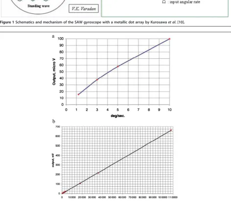
Figure 1Schematics and mechanism of the SAW gyroscope with a metallic dot array by Kurosawaet al. [10].
Figure 3Schematic view and mechanism of the SAW gyroscope using a standing wave mode by Wanget al.
Figure 4Sensitivity evaluation of the constructed SAW gyroscope according to rotation direction.
Figure 5Schematic view and mechanism of the SAW gyroscope with a one-port reflective delay line, from Ohet al.
about thex-axis, the Coriolis forces act on the perturb-ation masses perpendicularly, as shown in Figure 1, resulting in the generation of a secondary wave that propagates in the orthogonal direction of the standing wave. In a typical SAW delay line, one of the IDTs acts as a transmitter that converts the applied voltage variation
into acoustic waves while the other IDT receives these acoustic waves and converts them back into an output voltage. This reciprocity allows IDTs to be used either as SAW transmitters or as receivers. For this gyroscope, the IDTs for the sensors are used as receivers to detect the amplitude of the secondary SAWs, which are created by
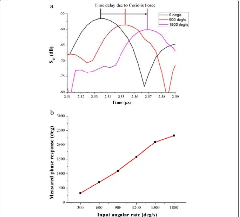
Figure 6Experimental results for the one-port reflective delay line gyroscope. (a)Results ofS11in the time domain for various rotation velocities.(b). Evaluated phase response with respect to angular rate.
Table 1 Properties and characteristics of SAW gyroscopes based on standing waves
References Author Size (Substrate) Frequency (MHz) Sensitvity Temperature compensation
[10] Kurosawaet al. - (128° LiNbO3) 15 - No
[11] Varadanet al. 1 × 1 mm2(128° LiNbO3) 74.2 705μv/deg/s No
[12] Wanget al. 1.2 × 0.75 mm2(128° LiNbO3) 80 119 Hz/deg/s Yes
the Coriolis effect when the gyroscope is subject to rota-tion. Despite their design, they cannot obtain any output signals owing to mismatch of the resonance frequencies.
Varadanet al.[11] obtained experimental results using this design concept. Figure 2 shows the measured output voltages from the SAW gyroscope for different angular rates. The SAW gyroscope response was evaluated using a rate table and a geophone setup. The gyroscope signal due to the Coriolis force propagates towards the SAWs, which emerge along with the diffracted signals from the resonator. It may be possible to separate the coupled signal from the gyroscope signal using phase-locked detection. Due to the difficulties in driving the rate table at lower rates, the sensitivity of the gyroscope was further measured using a geophone-pendulum setup. From the output voltage level of the BEI gyroscope, it can be seen that the table oscillation at 3 V excitation is 950° h−1.
Wang et al. [12,13] designed another concept SAW gyroscope using a standing wave. This gyroscope con-sists of a two-port SAW resonator, with a vibrating mass array within the cavity, and two SAW oscillators, one of which is used as a sensor and the other as a reference. Figure 3 shows a schematic of the structure and the operating principles of the proposed gyroscope. A stand-ing wave, generated by the two-port resonator, creates a metallic dot array at an antinode of the standing wave vibrating normal to the surface (± z-axis). When the SAW gyroscope is subjected to an angular rotation about the x-axis, the induced Coriolis force acts on the vibrating mass. The Coriolis force generates a secondary
Figure 7SAW MRG schematics and gyroscopic effects on the Rayleigh wave, from Leeet al.[15].
Figure 8Measured output of the SAW MRG depending on various angular rates. (a). Dynamic responses of the SAWMRG to several angular rates.(b). Frequency responses of the SAWMRG with respect to input angular rate.
SAW in the orthogonal direction of the primary stand-ing wave (±y-axis). This secondary SAW then interferes with the Rayleigh SAW propagating in the sensing device, causing a change in the acoustic velocity of the sensing device, and thus creating the resonant frequency of the SAW oscillator, which is used to detect the phase shift. Consequently, the angular rate can be evaluated by measuring the resonant frequency difference between the sensor oscillator and the reference oscillator. As shown in Figure 4, the sensitivity and linearity of the SAW gyroscope with rotation about the x-axis were measured to be 172 Hz/deg/s and 0.98, respectively. Moreover, negligible frequency differences between two delay lines were observed when rotating about the y -and z-axis, and were of lower magnitude than the white noise level. A superior single sensor directivity in the x-axis was observed.
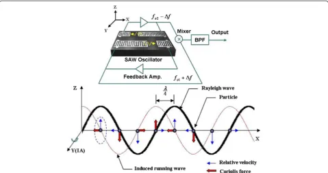
Figure 9Schematic view and mechanism of the SAW gyroscope based on progressive waves, from Ohet al.
Figure 10Measured output frequencies for various metallic dots. (a). Frequency responses depending on the position of the metallic dots in the delay line.(b). Frequency responses depending on the mass of the metallic dots.
Three years later, Ohet al. [14] proposed a gyroscope using a standing wave mode with a one-port reflective delay line. The gyroscope consists of metallic dots, reso-nators, and a SAW reflective delay line with an 80 MHz central frequency. As depicted in Figure 5, the operating principle is similar to the concept of Wanget al.[12,13], as previously described, and is as follows. When the gyroscope is rotating, the metallic dots induce a Coriolis force and generate a secondary SAW in the direction orthogonal to the standing wave. This wave interferes with the SAW flowing in the reflective delay line, result-ing in a change in the SAW velocity. Figure 6 shows the experimental results for the proposed SAW gyroscope, with a sensitivity of 1.23 deg/deg/s in phase response at an angular rate of up to 2000 deg/s.
Table 1 shows the properties of the SAW gyroscope using standing waves described above. Although Kurosawaet al. [10] failed to obtain experimental results with their device, they suggested using the standing wave mode and metallic dot array to enhance the sensitivity of the SAW gyroscope. Wanget al. [12,13] demonstrated a highly sensitive SAW gyroscope using a standing wave mode with two SAW oscillators to eliminate error sources such as temperature, pressure, and so on.
SAW gyroscope based on progressive wave
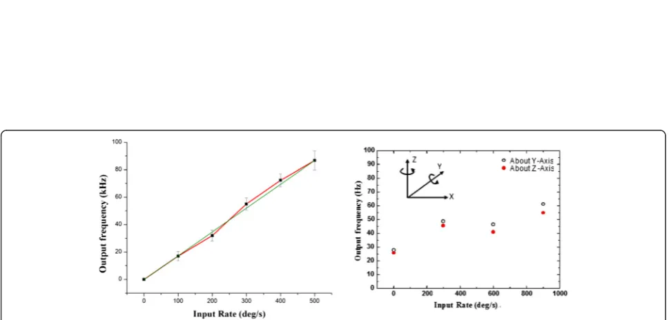
Lee et al. [15] proposed a SAW micro rate gyroscope (MRG) using two delay lines in 2007, as shown in Figure 7. The rotation vector perpendicular to the propagating axis causes a velocity change that is proportional to the input
rotation through the Coriolis force, because the particles of the Rayleigh wave are elliptically polarized on the sagittal plane. Therefore, these devices detect the fre-quency rather than the minute amplitude of a SAW and can use a temperature-stable material like ST-cut quartz despite the piezoelectric coupling coefficient. The SAWMRG consists of a delay-line structure, a low temperature co-fired ceramic (LTCC) package, and a cover glass. The oscillator operates at two fundamental frequencies. If the device is subject to rotation around they-axis, the operating frequency of the oscillator will vary according to the gyroscopic gain factor. Then, the output signals of both oscillators are fed into a multiplier and a band-pass filter to extract the frequency variation. Consequently, the angular rate of the SAWMRG can be sensed by measuring the frequency variation. The experi-ment was carried out at rotations of up to 2000 deg/s, and the results are shown in Figure 8. The sensitivity of the device and the residual standard deviation from the linear fit are 0.431 Hz/deg/s and 46.5 Hz, respectively.
Another type of SAW gyroscope using progressive waves was proposed by Ohet al.[16,17]. Figure 9 shows the schematics and the mechanism of a SAW gyroscope based on a progressive wave which consists of a vibrating mass, an absorber, and a two-SAW delay line; one is used as a sensing element and contains a vibrating mass in a cavity, while the other is used as a reference element. The SAW delay line oscillator operates based on a self-excited oscillator that consists of a delay line, a feedback amplifier, and a phase shifter, as shown in Figure 9(a). The oscillators with a delay line operate at their fundamental frequencies, f1 (reference part) and f2 (sensing part). A progressive wave is generated at the input transducer (left transducer) and propagated to the output transducer (right transducer). When the gyroscope is subjected to an angular rotation, the Coriolis force acts on the vibrating metallic dots. The direction of the force is the same as the direction of wave propagation, and the amplitude and vel-ocity of the wave are therefore changed (Δvc), causing a shift in the oscillation frequency (Δfc) of the sensing oscil-lator. By measuring the frequency difference between the sensing and reference oscillators, the input rotation can be evaluated without errors. The constructed device has been tested at an angular rate in the range of up to 1000 deg/s and the results are shown in Figure 10. The sensitivity was approximately 62.57 Hz/deg/s when metallic dots were positioned near the output IDT.
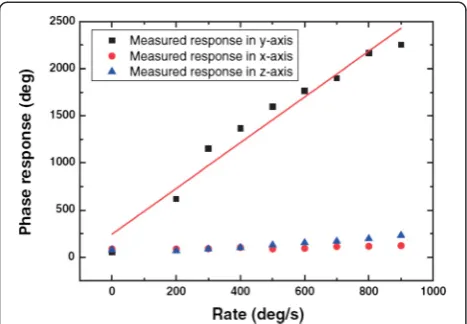
Figure 12Phase sensitivity evaluation of the wireless SAW gyroscope.
Table 2 Properties and characteristics of SAW gyroscopes based on progressive waves
References Author Size (Substrate) Frequency (MHz) Sensitvity Temperature compensation
[15] Leeet al. 9 × 9 mm2(ST-Quartz) 98.6 0.431 Hz/deg/s Yes
[16] Ohet al. 1.4 × 0.6 mm2(128° LiNbO3) 80.2 52.35 Hz/deg/s Yes
[18] Wanget al. - (128° LiNbO3) 434 2.42 deg/deg/s Yes
response of the gyroscope was measured at different rotation rates, up to 900 deg/s along the y-axis, and is depicted in Figure 12. According to their results, the sensitivity and linearity of the proposed device are 2.42 deg/deg/s and 0.956, respectively. Therefore, Wang et al. [18] successfully demonstrated the potential of the wireless and passive SAW gyroscope.
Table 2 shows properties of the various SAW gyro-scopes using progressive waves described above. The performance of the SAW gyroscope can be enhanced through the use of two delay lines. Moreover, Lee et al. [15] and Wanget al.[18] have attempted to improve the gyroscope sensitivity by using a differential scheme based on opposing wave propagation directions. Oh et al. [16,17] constructed a SAW gyroscope using a progressive wave with different masses and positions for the metallic dot array on an experimental basis. In particular, Wang et al.[18] successfully demonstrated a wireless and passive SAW gyroscope using two reflective delay lines.
Other gyroscopes using SAW
Figure 13 shows a multi-axis detectable SAW gyroscope utilizing a stacked configuration [19]. It consists of a silicon substrate and two SAW gyroscopes using pro-gressive waves, described in more detail in [16], in which the bottom element is used for y-axis detection and the top element is used forx-axis detection. The silicon sub-strate is used to protect the SAW gyroscope. The four sides are completely sealed by JSR photoresists (PR) to prevent interference from undesirable factors such as temperature and humidity. The two Si-substrates with
SAW gyroscopes are bonded with a conductive silver paste, in which a separation gap of about 200 μm is formed. When the gyroscope is subjected to an angular rotation about they-axis, a Coriolis force in the x -direc-tion is produced by the vibrating mass. Thus, the bottom SAW gyroscope is affected by the Coriolis force because the wave propagation direction is in the same direction as the Coriolis force. On the other hand, the Coriolis force significantly affects the top SAW gyroscope,
Figure 13Cross-sectional view of the multi-axis detectable gyroscope utilizing stacked configuration.
because the direction of wave propagation for the top SAW gyroscope is different to the direction of the Coriolis force. Conversely, when the gyroscope is subjected to an angular rotation about thex-axis, the Coriolis force in the y-direction is produced by a vibrating mass. In this case, the top SAW gyroscope is only affected by the Coriolis force.
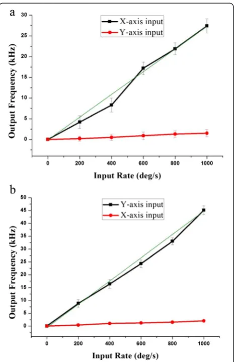
In this study, as the rotation speed was increased from 0 to 1000 deg/s along they-axis at 20°C, the mixed oscillator frequency difference of the bottom element increased linearly, as shown in Figure 14(a). However, the mixed oscillator frequency of the top element did not change, and the measured sensitivity and linearity of the SAW gyroscope were found to be 45.32 Hz/deg/s and 0.907, respectively. Next, the device was rotated counterclock-wise along thex-axis, from 0 to 1000 deg/s at 20°C. As the rotation speed increased, the mixed oscillator frequency difference of the top element increased linearly, as shown in Figure 14(b). In this case, the difference in signal from the bottom element is negligible, and the measured sensi-tivity and linearity of the SAW gyroscope were 27.34 Hz/ (deg/s) and 0.837, respectively. The sensitivity of the top element is lower than that of bottom element. This differ-ence can be ascribed to the fact that the applied electric energy to the top device is lower than that supplied to the bottom element, because of the different transmission lines of the electric signal and the highly resistive metal formed by electroplating.
Conclusion
Gyroscopes based on SAW have been reviewed. In com-parison to existing silicon-based MEMS gyroscopes, a SAW gyroscope is very attractive for a number of reasons. First, it has no suspended vibrating mechanical structure and is therefore more resistant to external shocks and vibrations. Second, frequency matching between the drive- and sense-mode frequencies in the absence of active tuning and feedback control is very easy. Finally, the temperature effect that causes a variation in the Young’s modulus and residual stress can be almost com-pletely eliminated. By comparing different structures of SAW-based gyroscopes and their mechanisms, we can see that the SAW gyroscope has the potential to be the highest performing gyroscope in the near future.
Competing interests
The authors declare that they have no competing interests.
Authors’contributions
HO carried out research works and writing of the manuscript. KJL carried out research works and KL carried out a survey on the gyroscope based on surface acoustic wave. SSY supervised all research works. All authors read and approved the final manuscript.
Authors’information
Haekwan Oh was born in Korea in 1981. He received his BS and Ph.D degrees in electrical engineering from Ajou University in 2007 and 2013,
respectively. He began working for next generation convergence sensor research center in KETI from 2013.
Ki Jung Lee received the BS, MS degrees in electrical engineering from Ajou University in 2007 and 2009. His major research areas include SAW sensors and micro mass spectrometer. He began working for Micro-system Lab., Ajou University from 2007 as a PhD candidate.
Keekeun Lee was born in Seoul, South Korea, in 1968. He received his MS degree from University of Florida, Gainesville, USA, in 1993 and his PhD degree in electrical engineering from Arizona State University, Tempe, USA, in 2000. After receiving his PhD degree, he worked as a post doctor and an assistant research professor for 4 years in bioengineering department at Arizona State University. In 2004, he joined Ajou University in S. Korea and currently he is a professor in electronics engineering department. He has published more than 60 papers in internationally renowned journal articles, mostly regarding wireless surface acoustic wave (SAW) sensors,
microstructured neural probe and its systems, organic-based hybrid solar cells, and so on.
Sang Sik Yang was born in Korea in 1958. He received his BS and MS degrees in mechanical engineering from Seoul National University in 1980 and 1983, respectively. In 1988, he received his PhD degree in mechanical engineering from the University of California, Berkeley. He was then a research assistant professor at New Jersey Institute of Technology. Since 1989, he has been a professor in the Department of Electrical and Computer Engineering at Ajou University. His research interests include the mechanism and actuation of microelectromechanical devices, SAW sensors and micro plasma devices.
Acknowledgements
This work was supported by the National Research Foundation of Korea (NRF), grant funded by the Korean government (MEST) (No. 2009-0081200).
Author details 1
Division of Electrical and computer engineering, Ajou University, Suwon 443-749, South Korea.2Next Generation Convergence Sensor Research Center, KETI, Seongnam 463-816, South Korea.
Received: 12 June 2014 Accepted: 20 October 2014
References
1. Wang R, Durgam SK, Hao Z, Vahala LL (2009) A SOI-Based Tuning-Fork Gyroscope With High Quality Factors. In: Tomizuka M (ed) Proceeding of SPIE Conference on Sensors and Smart Structures Technologies for Civil, Mechanical, and Aerospace Systems, vol 7292. SPIE., p 7292
2. Wang R, Cheng P, Xie F, Young D, Hao Z (2011) A multiple-beam tuning-fork gyroscope with high quality factors. Sensor Actuat A: Phys 166:22–33 3. Acar C, Schofield AR, Trusov AA, Costlow LE, Shkel AM (2009)
Environmentally robust MEMS vibratory gyroscopes for automotive applications. Sensors 9:1895–1906
4. Liu K, Zhang W, Chen W, Li K, Dai F, Cui F, Wu X, Ma G, Xiao Q (2009) The development of micro-gyroscope technology. J Micromech Microeng 19:113001
5. Binneg Y, Lao (1983) Surface Acoustic Wave Gyroscope. US patent 24 May 1983
6. Lao BY (1980) Gyroscopic Effect in Surface Acoustic Waves. Proceeding of IEEE ultrasonic symposium, In, p 687
7. Jose KA, Suh WD, Xavier PB, Varadan VK, Varadan VV (2002) Surface acoustic wave MEMS gyroscope. Wave Motion 36(4):367–381
8. Woods RC, Kalami H, Johnson B (2002) Evaluation of a novel surface acoustic wave gyroscope. IEEE Trans Ultrason Ferroelectr Freq Control 49:136–141 9. Varadan VK, Suh WD, Jose KA, Varadan VV (2001) Hybrid MEMS-IDT-based
accelerometer and gyroscope in a single chip. In: Varadan VK (ed) Proceeding of SPIE conference on smart structures and materials 2001: smart electronics and MEMS, vol.4334. SPIE., p 119
10. Kurosawa M, Fukula Y, Takasaki M, Higuchi T (1998) A surface-acoustic-wave gyro sensor. Sensor Actuat A: Phys 66:33–39
11. Varadan VK, Suh WD, Xavier PB, Jose KA, Varadan VV (2000) Design and development of a MEMS-IDT gyroscope. Smart Mater Struct 9:898–905 12. Wang W, Oh H, Lee K, Yoon S, Yang S (2009) Enhanced sensitivity of novel
surface acoustic wave microelectromechanical system-interdigital transducer gyroscope. Jpn J Appl Phys 48:06FK09
gyroscope using surface acoustic wave. Microelectron Eng 97:259–264
Submit your manuscript to a
journal and benefi t from:
7Convenient online submission 7Rigorous peer review
7Immediate publication on acceptance 7Open access: articles freely available online 7High visibility within the fi eld
7Retaining the copyright to your article