ECAP process improvement based on the design of
rational inclined punch shapes for the acute-angled
Segal 2
θ
-dies: CFD 2-D description of dead zone
reduction
A. V. Perig1and N. N. Golodenko2
1Manufacturing Processes and Automation Engineering Department, Donbass State Engineering Academy, Shkadinova Str. 72, 84313 Kramatorsk, Ukraine
2Department of Water Supply, Water Disposal and Water Resources Protection, Donbass National Academy of Civil Engineering and Architecture, Derzhavin Str. 2, 86123 Makeyevka, Ukraine
Correspondence to: A. V. Perig (olexander.perig@gmail.com)
Received: 27 July 2014 – Revised: 22 March 2015 – Accepted: 5 April 2015 – Published: 14 April 2015
Abstract. This article is focused on a 2-D fluid dynamics description of punch shape geometry improvement for Equal Channel Angular Extrusion (ECAE) or Equal Channel Angular Pressing (ECAP) of viscous incompress-ible continuum through acute-angled Segal 2θ-dies with 2θ <90◦. It has been shown both experimentally with physical simulation and theoretically with computational fluid dynamics that for the best efficiency under the stated conditions, the geometric condition required is for the taper angle 2θ0of the inclined oblique punch to be equal to the 2θangle between the inlet and outlet channels of the Segal 2θ-die. Experimentally and theoretically determined rational geometric condition for the ECAP punch shape is especially prominent and significant for ECAP through the acute angled Segal 2θ-dies. With the application of Navier-Stokes equations in curl transfer form it has been shown that for the stated conditions, the introduction of an oblique inclined 2θ0-punch results in dead zone area downsizing and macroscopic rotation reduction during ECAP of a viscous incompressible continuum. The derived results can be significant when applied to the improvement of ECAP processing of both metal and polymer materials through Segal 2θ-dies.
1 Introduction
For the last 20 years a number of research efforts in materi-als science related fields have been focused on wider devel-opment, implementation, commercialization and improve-ment of new material forming methods known as Severe Plastic Deformation (SPD) schemes (Boulahia et al., 2009; Haghighi et al., 2012; Han et al., 2008; Laptev et al., 2014; Minakowski, 2014; Nagasekhar et al., 2006; Nejadseyfi et al., 2015; Perig et al., 2013a, b, 2015; Perig and Laptev, 2014; Perig, 2014; Rejaeian and Aghaie-Khafri, 2014). The classi-cal SPD processing method is Segal’s Equal Channel Angu-lar Extrusion (ECAE) or Equal Channel AnguAngu-lar Pressing (ECAP) material forming technique (Segal, 2004). ECAE or ECAP realization is based on one or several extrusion
passes of a lubricated metal or polymer material through a die with two intersecting channels of equal cross-section (Segal, 2004). Materials’ processing by ECAP results in the accumu-lation of large shear strains and material structure refinement with physical properties enhancement (Boulahia et al., 2009; Nagasekhar et al., 2006; Nejadseyfi et al., 2015; Segal, 2004). The standard die geometry ABC-abc for ECAP processing is the so-called Segal 2θ-die geometry, where the inlet AB-ab and outlet BC-bc die channels have an intersection angle 2θ (Figs. 1–2). Moreover Segal 2θ-dies have neither exter-nal nor interexter-nal radii at the channel intersection points B; b (Figs. 1–2).
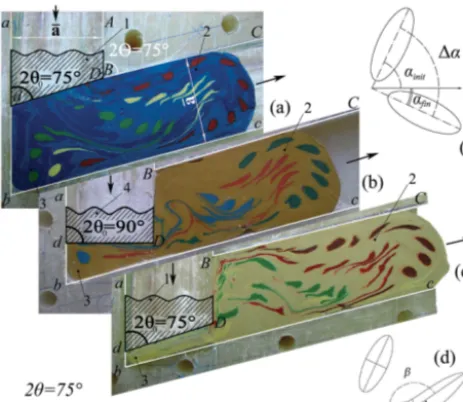
Re-Figure 1.Physical simulation with soft model-based experiments of punch shape (1, 4) influence on ECAP flow of viscous contuum (2) through acute-angled Segal die ABC-abc with channel in-tersection angle 2θ=75◦<90◦: (4) classical punch of rectangular shape dD in (b); (1) modified shape of inclined 2θ0-punch dD in (a)
and (c), where 2θ0=2θ; (3) the experimentally derived shape of
the dead zone for material flow during ECAP; the schematic dia-grams of macroscopic rotation (e) and rotational inhomogeneity (d) formation during viscous continuum ECAP.
jaeian and Aghaie-Khafri, 2014) to the solution of ECAP problems. This interest is results from growing applica-tion of ECAP SPD techniques to processing of polymers (Boulahia et al., 2009; Perig et al., 2010; Perig and Golo-denko, 2014a, b) and powder materials (Haghighi et al., 2012; Nagasekhar et al., 2006) where viscosity effects be-come essential.
At the same time the phenomenological description of polymer materials flow through Segal 2θ-dies with Navier-Stokes equations has not been adequately addressed in pre-viously known publications (Minakowski, 2014; Perig et al., 2010; Perig and Golodenko, 2014a, b; Rejaeian and Aghaie-Khafri, 2014). This underlines the importance of the present research, dealing with fluid dynamics 2-D simulation of ma-terial flow through the acute-angled Segal 2θ-dies with chan-nel intersection angles of 2θ >0◦and 2θ <90◦.
Another problem during ECAP material processing through the acute-angled Segal 2θ-dies with 2θ <90◦is
con-nected with the formation of large dead zones (3) in the vis-cous material flow in Fig. 1b as well as enormous and dan-gerous mixing 1 αof viscous material (2) in Fig. 1b and e during viscous continuum ECAP through acute-angled dies with channel intersection angles of 2θ <90◦when standard classical rectangular punches (4) are applied (Fig. 1b). So simple physical simulation experiments in Fig. 1b for viscous continuum ECAP through the die ABC-abc with 2θ=75◦ confirm the disadvantages of using a standard punch (4) with
Figure 2. Soft physical model of the workpiece after 3 ECAP passes through Segal 2θ-die via route C with modified shape of 2θ0
-inclined or 2θ0-beveled punch, where 2θ=2θ0=75◦.
rectangular shape AD-ad (2θ0=90◦) in Fig. 1b. It is very important to note that known approaches in published arti-cles (Boulahia et al., 2009; Haghighi et al., 2012; Han et al., 2008; Laptev et al., 2014; Minakowski, 2014; Nagasekhar et al., 2006; Nejadseyfi et al., 2015; Perig et al., 2013a, b; Perig and Laptev, 2014; Perig, 2014; Rejaeian and Aghaie-Khafri, 2014; Segal, 2004; Wu and Baker, 1997) have never addressed the possibility of changing the standard rectangu-lar punch shape AD-ad in Fig. 1b for material ECAP through acute-angled Segal dies with 2θ <90◦.
This fact emphasizes the importance and underlines the prime novelty of the present article addressing the vis-cous fluid dynamics description of the influence of classi-cal (Fig. 1b) and novel modified 2θ0-inclined or 2θ0-beveled (Figs. 1a, c and 2) punch shape AD-ad on viscous flow fea-tures of processed workpieces during ECAP SPD pressure forming through acute-angled Segal 2θ-dies with channel in-tersection angles of 2θ >0◦and 2θ <90◦.
2 Aims and scopes of the article – prime novelty statement of research
The present article is focused on the experimental and the-oretical description of viscous workpiece flow through 2θ acute-angled angular dies of Segal geometry during ECAP by a classical rectangular punch and a novel modified 2θ 0-inclined or 2θ0-beveled punch.
The aim of the present research is the phenomenologi-cal continuum mechanics based description of viscous work-piece flow through the 2θ acute-angled angular dies of Se-gal geometry during ECAE with an application of classical rectangular and novel modified 2θ0-inclined or 2θ0-beveled punch shapes.
mod-the introduction of initial circular gridlines to study mod-the punch shape influence on viscous workpiece ECAP flow through the 2θangular acute-angled dies of Segal geometry.
The prime novelty of the present research is the numerical finite-difference solution of Navier-Stokes equations in the curl transfer form for the viscous workpiece flow through 2θ acute-angled angular dies of Segal geometry during ECAP, taking into account the classical rectangular and novel mod-ified 2θ0-inclined or 2θ0-beveled punch shapes.
3 Physical simulation study of punch shape influence on viscous flow
Physical simulation techniques using plasticine workpiece models are often used in material forming practice (Chijiwa et al., 1981; Han et al., 2008; Laptev et al., 2014; Perig et al., 2010, 2013a, b, 2015; Perig and Laptev, 2014; Perig and Golodenko, 2014a, b; Perig, 2014; Sofuoglu and Rasty, 2000; Wu and Baker, 1997).
In order to estimate the character of viscous flow dur-ing ECAP through a 2θ acute-angled angular die of Se-gal geometry ABC–abc under the action of a classical rect-angular punch and a novel modified 2θ0-inclined or 2θ 0-beveled punch shapes we have utilized physical simulation techniques in Figs. 1–2. The plasticine workpiece models in Figs. 1–2 have been extruded through a ECAP die ABC– abc with channel intersection angle 2θ=75◦ using a
stan-dard punch (4) with rectangular shape (2θ0=90◦) in Fig. 1b and novel modified 2θ0=75◦-inclined or 2θ0=75◦-beveled punch (1) in Figs. 1a, c and 2 as the first experimental ap-proach to polymeric materials flow (Figs. 1–2).
The aim of the physical simulation is an experimental study of dead zone abc formation and deformation zone abc location during viscous ECAP flow of workpiece plasticine models under the external action of rectangular and inclined punches. The physical simulation in Figs. 1–2 is also focused on the experimental visualization of rotary modes of SPD during ECAP of viscous polymer models for the different punch geometries. The experimental results in Figs. 1–2 are original experimental research results, obtained by the au-thors.
The plastic die model of ECAP die ABC-abc with channel intersection angle<ABC=<abc=2θ=75◦and the width of inlet aA and outlet cC die channels 35 mm is shown in Figs. 1–2. Potato flour was used as the lubricator in Figs. 1– 2.
heating of the plasticine (Fig. 1) pieces with different colors to the half-solid state, and placing the half-solid multicolor plasticine (Fig. 1) into the through-holes of the frozen paral-lelepipeds using a squirt without needle technique.
In this way the initial plasticine-based (Fig. 1) circu-lar gridlines were marked throughout the initial plasticine (Fig. 1) workpieces. The initial circular gridlines transform into deformed elliptical ones as workpieces flow from inlet to outlet die channels during ECAP (Figs. 1a, c and 2). The gridline-free dead zones (p. b) were visualized through the physical simulation techniques introduction in Figs. 1–2. It was found that dead zone (p. b) formation takes place in the vicinity of the external angle abc of channel intersection zone Bb. It was experimentally shown that the best reduction of dead zone size (3) for an ECAE die with 2θ=75◦could be achieved through the replacement of the standard rectangu-lar punch AD-ad with (2θ0=90◦) in Fig. 1b with the new 2θ0-inclined or 2θ0-beveled punch AD-ad with 2θ0=75◦.
It was experimentally found in Figs. 1–2 that the deforma-tion zone BCDc during ECAP of the viscous models is not located in the channel intersection zone Bb but is located in the beginning of the outlet die channel BC-bc. The relative location of the elliptical markers in outlet die channel BC-bc show the formation of two rotary modes of SPD during ECAP (Fig. 1).
Checking the successive locations of one color elliptical markers in Fig. 1, we see that the major axis of every ellip-tical marker rotates with respect to the axis of the outlet die channel bc. We define the term of macroscopic rotation as the relative rotation of the major axis of an elliptical marker with respect to the flow direction axis bc. The macroscopic rotation is the first visually observable rotary mode during ECAP forming of the viscous workpiece model.
Figure 3.Computational flow lines for the Segal die with 2θ=75◦ for the coordinate steps ξ=1.10 mm; η=1.44 mm for the rect-angular punch dD (2θ0=90◦) (a) and for the inclined punch dD
(2θ0=75◦) (b), where time iteration step istit=610 µs, transition
time isttr=11.3 s.
the ECAP die channel intersection angle 2θand 2θ0-punch shape geometry.
The experimental results in Figs. 1–2 have indicated the formation of the following zones within worked materials’ volumes: (I) the dead zone (p. b); (II) the deformation zone BCDc; (III) the macroscopic rotation zone (BC-bc), and (IV) the zone of rotational inhomogeneity (BC-bc). The com-plex of physical simulation techniques in Figs. 1–2 intro-duces the initial circular gridlines technique with the applica-tion of plasticine workpieces with the initial circular colorful gridlines in the shape of initial colorful cylindrical plasticine inclusions (Fig. 1). The application of the initial circular grid-lines experimental technique and the introduction of a novel modified 2θ0-inclined or 2θ0-beveled punch shapes has not been addressed in previous known ECAP research (Boulahia et al., 2009; Haghighi et al., 2012; Han et al., 2008; Laptev et al., 2014; Minakowski, 2014; Nagasekhar et al., 2006; Ne-jadseyfi et al., 2015; Perig et al., 2013a, b; Perig and Laptev, 2014; Perig, 2014; Rejaeian and Aghaie-Khafri, 2014; Segal, 2004; Wu and Baker, 1997).
The proposed complex of experimental techniques for physical simulation of SPD during ECAP in Figs. 1–2 will find the further applications in the study of viscous ECAP through the dies with more complex Iwahashi, Luis-Perez, Utyashev, Conform and equal radii geometries for the differ-ent punch shape geometries and differdiffer-ent routes of multi-pass ECAP working.
Figure 4.Computational dimensionless flow functionψfor the Se-gal die with 2θ=75◦for the rectangular punch dD (2θ0=90◦) (a)
and for the inclined punch dD (2θ0=75◦) (b).
Figure 5.Computational dimensionless curl functionζfor the Se-gal die with 2θ=75◦for the rectangular punch dD (2θ0=90◦) (a)
and for the inclined punch dD (2θ0=75◦) (b).
4 Numerical simulation study of punch shape influence on flow lines, and punching pressure during viscous ecap flow through Segal 2θ-dies
In order to derive the mathematical model of the viscous ma-terial flow during ECAP through the acute-angled Segal 2θ -die taking into account the punch shape AD-ad effect on vis-cous flow dynamics we will apply the Navier-Stokes equa-tions (Appendices A–D). The results of the numerical simu-lation study are shown in computational diagrams in Figs. 3– 10.
Computational results in Figs. 3–10 illustrate the punch shape influence on geometry (Fig. 3), kinematics (Figs. 4– 8) and dynamics (Figs. 9–10) of the viscous flow during ECAP. Computational plots in Figs. 3–10 are based on a finite-difference solution of the Navier–Stokes equations in curl transfer form Eqs. (A1)–(A2) with initial Eq. (B1) and boundary Eqs. (C1)–(C7) conditions.
Instabilities of the numerical solutions, which appear at the outlet frontiers cC (Figs. 3–10), propagate upstream.
di-Figure 6. Computational u components of flow velocities for the Segal die with 2θ=75◦ for the rectangular punch dD (2θ0=90◦) (a) and for the inclined punch dD (2θ0=75◦) (b).
Figure 7. Computational v components of flow velocities for the Segal die with 2θ=75◦ for the rectangular punch dD (2θ0=90◦) (a) and for the inclined punch dD (2θ0=75◦) (b).
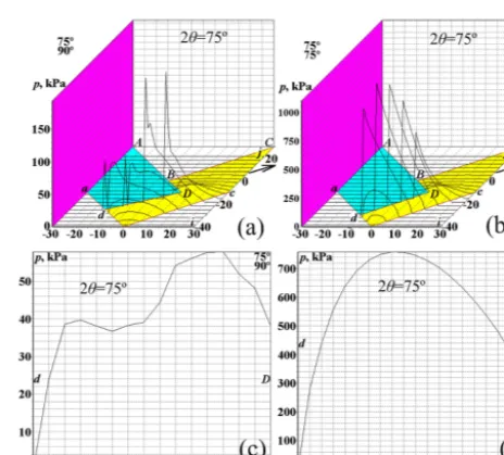
agrams for ECAP punching pressure in Figs. 9–10 show that the application of the standard rectangular punch with 2θ0=90◦requires lower punching pressures (Fig. 10). The CFD-based simulation in Figs. 9–10 indicates that the use of the modified 2θ0-inclined or 2θ0-beveled punch shapes re-quires higher punching pressures for ECAP of viscous in-compressible continuum through the acute-angled Segal 2θ -dies with 2θ <90◦.
Higher values of punching pressure for modified 2θ0 -inclined or 2θ0-beveled punch shapes in comparison with the standard rectangular punch with 2θ0=90◦ in Figs. 9– 10 result from the fact that the compressive strains in such schemes are higher than shear strains.
So in order to force the plasticine model through the 2θ-die by the modified 2θ0-inclined punch we have to apply higher punching force in order to reach the necessary shear stresses. This fact is shown in Figs. 9–10.
The increased punching pressure required for the modi-fied 2θ0-inclined punches and for the acute angled 2θ-dies with 2θ <90◦results in decreased dead zone in angle b and a decreased shear stress component (Figs. 6b, 7b, 8b, 9b, d, and 10).
For the modified 2θ0-inclined punches and the obtuse an-gled 2θ-dies with 2θ >90◦the decreased punching pressure
results from increased effective punch area dD and increased shear stress component (Fig. 10).
Figure 8. Computational dimensionless full flow velocities w
for the Segal die with 2θ=75◦ for the rectangular punch dD (2θ0=90◦) (a) and for the inclined punch dD (2θ0=75◦) (b).
Figure 9. Computational dimension punching pressure for the Segal die with 2θ=75◦ for the rectangular punch dD (2θ0=90◦) (a, c) and for the inclined punch dD (2θ0=75◦) (b, d).
5 Discussion of derived results
The technological issue addressed in this article has di-rect industrial importance in material forming applications. The introduction of the fluid dynamics numerical simulation (Figs. 3–10) provides us with a better understanding of phys-ical simulation results in Figs. 1–2.
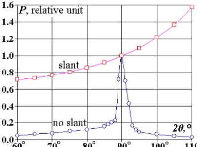
-Figure 10. Computational dimensionless punching pressures for plasticine viscous liquid flow through Segal dies with 60◦≤2θ≤110◦ for the rectangular punch dD (2θ0=90◦) ()
and for the modified 2θ0-inclined or 2θ0-beveled punch dD
(2θ0=2θ) ().
punch with 2θ0=75◦(inclined punch in Figs. 1a, c, 2, 3b, 4b, 5b, 6b, 7b, 8b, 9b, d, 10) we see a smaller dead zone size dDb. Computational flow lines (Fig. 3) are the lines near which flow function ψ (Fig. 4) is constantψ=const. The computed effect in Fig. 4, which shows the absence of the “sawtooth” shape of the ψ-function over the die area dDb confirms that the dDb area is just the dead zone and not a vortex or eddy zone with circulating flow. Figure 5 show us that the curl functionζ=0 is also zero in the dead zone dDb. Polycrystalline material is a natural composite, which con-tains ultra fine single crystals and amorphous viscous fluid between single crystals for fastening and connecting these single crystals among themselves. Laminar-flow layers of such amorphous fluid move with different velocities as well as single crystal sides, adjacent to laminar-flow layers. Curlζ (Eq. A2) characterizes single crystal relative rotation during its linear displacement along the flow lines in Fig. 5. As a re-sult of internal friction the contacting facets of single crystals become smooth like smoothing of river or sea pebbles under action of viscous flow.
This is the hydrodynamic explanation of the increase of the material plasticity during ECAP, which follows from the computational diagrams in Figs. 3–10. Under the action of mechanical loads at the boundaries of the contacting facets of single crystals, there appear no micro-cracks because of their flatness. The curl is zero in dead zone dDb. So in the material dead zone dDb no smoothing of single crystals facets takes place. As a result, material plasticity cannot be improved in the material dead zone dDb.
Such hydrodynamic illustrations (Figs. 3–10) directly con-firm experimentally derived results (Figs. 1–2) with physical simulation of punch shape effect on material flow kinematics during ECAE through the acute-angled Segal 2θ-die.
6 Conclusions
In the present work we addressed the 2θ0-punch shape effect on material flow dynamics during ECAP through the numer-ical solution of the boundary value problem Eqs. (A1)–(A2), (B1), (C1)–(C7) for Navier–Stokes equations in curl transfer form (Figs. 3–10), taking into account the standard rectangu-lar and improved 2θ0-inclined or 2θ0-beveled punch shapes.
Both physical (Fig. 1b) and fluid dynamics (Figs. 3a, 4a, 5a, 6a, 7a, 8a, 9a, c, 10) simulations show that the appli-cation of a standard rectangular punch with 2θ0=90◦ for workpiece ECAP through acute-angled Segal 2θ-dies with 2θ <90◦is highly undesirable because of the resulting large material dead zone areas dDb in the neighborhood of the ex-ternal die angle 2θ=<(abc).
Both physical (Figs. 1a, c and 2) and fluid dynamics (Figs. 3b, 4b, 5b, 6b, 7b, 8b, 9b, d, 10) simulations reveal that the introduction of 2θ0-inclined or 2θ0-beveled punch shapes with dDbc for material ECAP processing through the acute-angled Segal 2θ-dies with 2θ <90◦and 2θ
where the dimensionless curl function will be defined as (Fig. 5):
ζ =∂u
∂y − ∂v
∂x. (A2)
Appendix B: Initial conditions for curl transfer equation
We now study the steady-state regime of viscous flow for a physical model of polymer material (Figs. 3–10). So the initial conditions we will assume in the form of a rough ap-proximation to the stationary solution (Figs. 3–10):
u0i,j=0; vi,j0 =0; ζi,j0 =0; ψi,j0 =0. (B1)
Appendix C: Boundary conditions for curl transfer equation
The boundary conditions for the die walls we will define as the viscous material “sticking” to the walls of the die (Figs. 3–10).
At the inner upper boundary DBC (Figs. 3–10) we have
ψi,j =1; ζi,j=1. (C1)
At the external lower boundary dbc (Figs. 3–10) we have
ψi,j =0; ζi,j=0. (C2)
For the punch frontal edge dD (Figs. 3–10) we have
ψ10,−10=1; ψ9,−11=1−2/N;
ψi,j =ψi+2,j+2−2/N, (C3)
whereN is the quantity of ordinate steps along the channel width.
For the angular points, which are located in the vertices of the concave angles b and B (Figs. 3–10) we have
ζi,j=0. (C4)
For the angular point D (Figs. 3–10) of the convex angle in the finite-difference equation, written for the mesh point (10,
−11) we have the following curl
ζ10,10=2ψ10,−11. (C5)
For the angular point D (Figs. 3–10) of the convex an-gle in the finite-difference equation, written for the mesh point (11, 10) we have the curl
parameters for the problem
The numerical results of integration of curl transfer Eqs. (A1)–(A2) with initial Eq. (B1) and boundary Eqs. (C1)–(C7) conditions are outlined in Figs. 3–10 for the following numerical values:
– the dimensional width of inlet and outlet die channels is a=35 mm;
– the dimensional length of die channel is L=16·a
=16·35×10−3m=0.56 m;
– the dimensional average ECAP punching velocity is U0=0.1×10⁻³m s−1;
– the dimensional time of processed workpiece mate-rial motion in die channel is t∗=L/U0=0.56/(0.1
×10−3)=5600 s;
– the maximum value of dimensionless curl isζ=1; – the dimensional curl isζ=ζ·U0/a=(1×0.1×10−3
m s−12)/(35×10−3m)=2.86×10−3s−1;
– the dimensional average angular velocity of rota-tion for viscous material layers is ω= |rotw|/2=
ζ /2=1.43×10−3s−1;
– the number of turns for viscous material layers during the time of workpiece material motion in die channel is N∗=ωt∗/2π=(1.43×10−3×5600)/2×3.14)=1.27; – the dimensional density of the viscous plasticine
physical model of extruded polymer material is ρ=1850 kg m−3;
– the dimensional plasticine yield strength is σs= 217 kPa (Sofuoglu and Rasty, 2000);
– the dimensional specific heat capacity of plasticine ma-terial isc=1.004 kJ/(kg K−1);
– the dimensional thermal conductivity is λ=0.7 J/ (m s−1K−1) (Chijiwa et al., 1981);
– the dimensional kinematic viscosity for viscous Newto-nian fluid model of plasticine workpiece during ECAE isνvis=ηvis/ρ=1.2×106/1850=648.648 m2s−1; – Reynolds number is Re=U0aρ/ηvis=U0a/νvis=
5.396×10⁻⁹;
– the half number of coordinate steps along the x and yaxes isN=40;
– the number of coordinate steps along thex andy axes is 2×N=80;
– the relative error of iterations ise=1/1000;
– the dimensional time moment for the first isochrone building ist1=100 s;
– die channel intersection angle of Segal die is 2θ=75◦;
– punch shape inclination angles adD are 2θ0=90◦ (rect-angular punch in Figs. 1b, 3a, 4a, 5a, 6a, 7a, 8a, 9a, c, 10) and 2θ0=75◦(inclined punch in Figs. 1a, c, 3b, 4b, 5b, 6b, 7b, 8b, 9b, d, 10);
– the dimensional horizontal and vertical coordinate steps along the x– and y axes are ξ=1.10 mm and η=1.44 mm for angular die with 2θ=75◦;
– the dimensional time iteration step isτ=tit=610 µs for ECAP die with 2θ=75◦;
References
Boulahia, R., Gloaguen, J.-M., Zaïri, F., Naït-Abdelaziz, M., Seguela, R., Boukharouba, T., Lefebvre, J. M.: Deformation behaviour and mechanical properties of polypropylene pro-cessed by equal channel angular extrusion: Effects of back-pressure and extrusion velocity, Polymer, 50, 5508–5517, doi:10.1016/j.polymer.2009.09.050, 2009.
Chijiwa, K., Hatamura, Y., and Hasegawa, N.: Characteris-tics of plasticine used in the simulation of slab in rolling and continuous casting, T. Iron Steel I. Jpn., 21, 178–186, doi:10.2355/isijinternational1966.21.178, 1981.
Haghighi, R. D., Jahromi, A. J., and Jahromi, B. E.: Simulation of aluminum powder in tube compaction using equal chan-nel angular extrusion, J. Mater. Eng. Perform., 21, 143–152, doi:10.1007/s11665-011-9896-1, 2012.
Han, W. Z., Zhang, Z. F., Wu, S. D., and Li, S. X.: Investigation on the geometrical aspect of deformation during equal-channel an-gular pressing by in-situ physical modeling experiments, Mat. Sci. Eng. A, 476, 224–229, doi:10.1016/j.msea.2007.04.114, 2008.
Laptev, A. M., Perig, A. V., and Vyal, O. Y.: Analysis of equal chan-nel angular extrusion by upper bound method and rigid blocks model, Mat. Res., São Carlos (Mater. Res.-Ibero-Am. J.), 17, 359–366, doi:10.1590/S1516-14392013005000187, 2014. Minakowski, P.: Fluid model of crystal plasticity: numerical
simula-tions of 2-turn equal channel angular extrusion, Tech. Mechanik, 34, 213–221, 2014.
Nagasekhar, A. V., Tick-Hon, Y., and Ramakanth, K. S.: Mechan-ics of single pass equal channel angular extrusion of powder in tubes, Appl. Phys. A, 85, 185–194, doi:10.1007/s00339-006-3677-y, 2006.
Nejadseyfi, O., Shokuhfar, A., Azimi, A., and Shamsborhan, M.: Improving homogeneity of ultrafine-grained/nanostructured ma-terials produced by ECAP using a bevel-edge punch, J. Mater. Sci., 50, 1513–1522, doi:10.1007/s10853-014-8712-3, 2015.
of ECAE through a multiple-angle die with a mov-able inlet wall, Chem. Eng. Commun., 201, 1221–1239, doi:10.1080/00986445.2014.894509, 2014a.
Perig, A. V. and Golodenko, N. N.: CFD 2D simulation of viscous flow during ECAE through a rectangular die with parallel slants, Int. J. Adv. Manuf. Technol., 74, 943–962, doi:10.1007/s00170-014-5827-2, 2014b.
Perig, A. V., Laptev, A. M., Golodenko, N. N., Erfort, Y. A., and Bondarenko, E. A.: Equal channel angular extru-sion of soft solids, Mat. Sci. Eng. A, 527, 3769–3776, doi:10.1016/j.msea.2010.03.043, 2010.
Perig, A. V., Zhbankov, I. G., and Palamarchuk, V. A.: Ef-fect of die radii on material waste during equal chan-nel angular extrusion, Mater. Manuf. Process., 28, 910–915, doi:10.1080/10426914.2013.792420, 2013a.
Perig, A. V., Zhbankov, I. G., Matveyev, I. A., and Pala-marchuk, V. A.: Shape effect of angular die external wall on strain unevenness during equal channel an-gular extrusion, Mater. Manuf. Process., 28, 916–922, doi:10.1080/10426914.2013.792417, 2013b.
Perig, A. V., Tarasov, A. F., Zhbankov, I. G., and Romanko, S. N.: Effect of 2θ-punch shape on material waste during ECAE through a 2θ-die, Mater. Manuf. Process., 30, 222–231, doi:10.1080/10426914.2013.832299, 2015.
Rejaeian, M. and Aghaie-Khafri, M.: Study of ECAP based on stream function, Mech. Mater., 76, 27–34, doi:10.1016/j.mechmat.2014.05.004, 2014.
Roache, P. J.: Computational fluid dynamics, Hermosa Publishers, Albuquerque, 1976.
Segal, V. M.: Engineering and commercialization of equal chan-nel angular extrusion (ECAE), Mat. Sci. Eng. A, 386, 269–276, doi:10.1016/j.msea.2004.07.023, 2004.
Sofuoglu, H. and Rasty, J.: Flow behavior of Plasticine used in phys-ical modeling of metal forming processes, Tribol. Int., 33, 523– 529, doi:10.1016/S0301-679X(00)00092-X, 2000.