IJIRT 148907
INTERNATIONAL JOURNAL OF INNOVATIVE RESEARCH IN TECHNOLOGY240
Overview of Interfacing Data Converters with 8085
Microprocessor and its application
Renu Bundel
1, Kumar pal Singh
2 1,2Asst. Professor, Aryabhatta College of Engineering and Research Center, Ajmer, Rajasthan, India
Abstract- Sometimes the information available for processing in a microprocessor-based system is in digital form while in most cases it is available in analog form. For example, the outputs of the digital voltmeter, digital frequency meter, digital clock, and calculators, etc. are available in digital form but most physical quantities such as temperature, pressure, light, voltage and current, etc. gives information in analog form. It is often necessary to convert the information in one form to another form for interfacing with the system.
Index terms- A/D and D/A converters, binary ladder, comparator, control unit, binary counter, clock pulse, integrator, logic gates, integrated circuits.
I.INTRODUCTION
It converts digital data into the equivalent analog current. Therefore I to V converter is used to convert analog output current of DAC to an equivalent analog voltage. PA0-PA7 pins of Port A are connected to D0-D7 pins of DAC. ADC (Analog to Digital Converter) works with Intel 8085 Microprocessor. The Analog to Digital Conversion is a quantizing process. Here the analog signal is represented by equivalent binary states. The A/D converters can be classified into two groups based on their conversion techniques [1].
In the first technique, it compares given analog signal with the initially generated equivalent signal. In this technique, it includes successive approximation, counter and flash type converters. In another technique, it determines the changing of analog signals into time or frequency. This process includes integrator-converters and voltage-to-frequency converters. The first process is faster but less accurate; the second one is more accurate. As the first process uses flash type, so it is expensive and difficult to design for high accuracy [2].
II. HISTORY
Initially Microprocessor was designed by the United States of America and BUSICOM of Japan in the year 1971. The first Microprocessor Intel 4004 was a 4 bit P-type Metal Oxide Semi-Conductor (PMOS) Microprocessor. [3]Intel introduced two 8 bit microprocessors 8008 in the year 1972 and 8080 in 1973. The 2nd one was the most popular microprocessor of the early 70s. 8080 was an NMOS microprocessor. NMOS microprocessor is popular than PMOS as NMOS technology is faster and provide higher density than that of PMOS. The enhanced version of 8080 was 8085 [1, 7].
Microprocessor 8085 was introduced by Intel in the year 1977 [8]. The clock and controller of Intel 8080 were on a separate chip and it utilizes two separate power supplies. So 8080 was not a complete CPU on a single chip. But Intel 8085 has its clock and control circuit fabricated on a single chip [1]. The model number “5” came from the fact that Intel 8085 requires only +5-volt (V) power supply by using depletion-mode of transistors. This kind of chip requires a minimum of external units like RAM, ROM, 8-bit latches, etc [8].
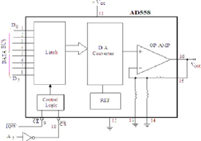
III. MICROPROCESSOR COMPATIBLE D/A CONVERTER
IJIRT 148907
INTERNATIONAL JOURNAL OF INNOVATIVE RESEARCH IN TECHNOLOGY241
Fig. 3.1 Compatible D/A converter with an op-ampIV. ADC 0808/0809
The ADC 0808/0809 is an 8-bit A/D converter with 8-channel multiplexer which can be interfaced with the microprocessor. It is the most popular, inexpensive and widely 414 used A/D converter. It is a monolithic CMOS device which uses the method of successive approximation A/D converter. It does not require external zero and full scale adjustment. The device operates with +5V d.c. supply. The conversion time is 100 μsec at clock frequency of 640 KHz. The 8-channel multiplexer can directly access any of the 8 single ended analog signals [5].
The ADC 0808 / 0809 offers following features:
High speed
High accuracy
Minimal temperature dependence
Excellent long term accuracy and repeatability
Consume minimal power
Fig. 4.1 ADC pin diagram
The pin diagram and schematic block diagrams of this IC ADC 0808 / 0809 are shown in figures 4.1 respectively. The pin description of this IC is given as:
Pins 26-28 and 1-5 – are 8 input channels IN0– IN7 (multiplexed), which are selected by the three (address) lines ADD A, ADD B and ADD C.
Pin 6 SOC – Start of conversion pin. A high to this pin starts the conversion.
Pin 7 EOC – End of conversion. This an output terminal and gives high signal when the conversion ends.
Pins 21-18, 8, 15-14 & 17 8-bit outputs (latch) pins to be connected to the port of 8255.
Pin 9 OE – Output enable pin which is connected to the positive supply.
Pin 10 CLK – Clock terminal. It is to be connected either to the external clock of frequency between 10 to 1280 KHz or the clock out frequency of the 8085A after dividing it by a factor of four may be connected to this pin.
Pin 11 VCC – Supply pin (+5 V).
Pin 12 Ref (+) – Reference pin which is to be connected to the + supply.
Pin 13 GND – Ground terminal.
Pin 16 Ref (-) – Reference pin to be connected to the ground.
Pins 25-23 – Address pins (ADD A, ADD B and ADD C). These pins are used to select the channels as given below (Table 4.1):
Table 4.1 Pins used for channels Channels Selected Address lines
C B A
IN0 0 0 0
IN1 0 0 1
IN2 0 1 0
IN3 0 1 1
IN4 1 0 0
IN5 1 0 1
IN6 1 1 0
IJIRT 148907
INTERNATIONAL JOURNAL OF INNOVATIVE RESEARCH IN TECHNOLOGY242
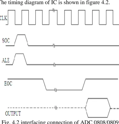
The timing diagram of IC is shown in figure 4.2.Fig. 4.2 interfacing connection of ADC 0808/0809
The interfacing connection of ADC 0808 / 0809 with the microprocessor 8085A is shown in figure 4.2. In this circuit an analog voltage, whose equivalent digital value is to be obtained, is applied to IN0. The output terminals of the ADC are connected to Port A of 8255 PPI. This port is to be used as the input port. The PC7 terminal of the Port CUpper is connected to the End of Conversion terminal of the ADC. This port is also used as the input port. The port CLower is used as the output port. The three terminals PC0 to PC2 are connected to the three address pins of the ADC 0808 / 0809 for the selection of input channel. The PC3 terminal is connected to the SOC (Start of Conversion) and the ALE terminals of the converter.
V. A/D CONVERTER USING D/A CONVERTER AND SOFTWARE
The A/D converter can also be realized using the D/A converter and the software. For this purpose the software is used to implement successive approximation A/D converter. Figure 5.1 shows the interfacing connection for this. The input analog voltage is applied to a comparator. This voltage is compared by the output of the D/A converter. The output of the comparator is sensed by the microprocessor through the PC7 of the 8255. A digital input is applied to the D/A converter, through port A of 8255.
Fig. 5.1 interfacing connection
The microprocessor first applies 00 H as the digital input to the DAC 0808 and checks through PC7 for high signal. If a high pulse does not appear at the output terminal of the comparator, the microprocessor increments the digital input by 1 and the process is repeated till a high signal appears at the output of the comparator. As a high signal appears the microprocessor stops successive approximation and the corresponding digital input value is stored in the memory location. This digital value is equivalent to the analog signal applied at VIN terminal of the comparator [5].
VI. APPLICATION
IJIRT 148907
INTERNATIONAL JOURNAL OF INNOVATIVE RESEARCH IN TECHNOLOGY243
upgrading in performance with minimal redesign ofthe product and minimum production cost. Intel 8085 has a set of instructions like MOV, MVI, STA, ADD, DIV, JMP etc. Using these kinds of instructions, microprocessor performs various operations like transfer of data, addition, subtraction, branching, storing etc [6, 8].
Some other following applications are:
Real time clock with on/off timer
Microprocessor based led dial clock
Design of microprocessor based running light
Microprocessor based automatic school bell system
Microprocessor based traffic light
Microprocessor based stepper motor control
Microprocessor based washing machine controller
Microprocessor based water level controller
Microprocessor based temperature controller
VII. CONCLUSION
After the study of all the details of microprocessor 8085, including the assembly language programming and peripheral devices we are now in a position to design some microprocessor based systems. Real time clock with on/off timer, running light, washing machine control, water level control etc. This process includes integrator-converters and voltage-to-frequency converters. The first process is faster but less accurate; the second one is more accurate. As the first process uses flash type, so it is expensive and difficult to design for high accuracy.
Microprocessor reduces cost of processing power, increases reliability focuses on real time applications and it is faster in speed also. It is used in smallest embedded system to largest main frames and super computers. Due to its wide verities of uses it has revolutionized the human civilization.
ACKNOWLEDGMENT
The First author wish to express her thanks to the Principal, Aryabhatta College, Ajmer to carry out the above work in Department of Electrical and Electronics and the Second author wish to express his sincere thanks to the Former Chairman Prof. Amit
Shastri for their encouragement and support to undertake the present work and providing the facilities in Department of Electronics. He also expresses his thanks to his colleagues in Department of Electrical and Electronics for their support.
REFERENCES
[1] R. S. Gaonkar, Microprocessor Architecture, Programming, and Applications with the 8085, 5th ed., Upper Saddle River, NJ: Prentice Hall, 2002, pp. 1–171.
[2] Dr. D.K. Kaushik, “An introduction to Microprocessor 8085” ebook Dhanpat Rai Publishing company.
[3] SenSK; Understanding 8085/8086 Microprocessor and Peripheral Ics through Questions and Answers; New Age International (P) Ltd. 2nd Edition, 2010
[4] S. K. Breckling, Microprocessor 8085 and Its Interfacing, 2nd ed., New Delhi, India: PHI Learning, 2011.
[5] Ramesh S. Gaonkar, “Microprocessor Architecture, Programming, and Applications with the 8085/8085A”, Wiley Eastern Limited. [6] Yadav J, Bhatia K & Kaushil K; Microprocessor,
IJRIT International Journal of Research in Information Technology, Volume 2, Issue 10, October 2014, Pg. 14-18
[7] RAM. B. Fundamentals of Microprocessor and Microcomputers; Dhanpat Rai Publications. 8th Edition, 2012
[8] Kathuria K, Malhotra B, RaiK; 8085 Microprocessors, IJRIT International Journal of Research in Information Technology, Volume 2, Issue 10, October 2014, Pg. 258-263
[9] Durga Devi R, Uma S, Mirunalinie S. A survey on Embedded System; International Journal of Engineering Research 3 (2), 2015, 5 - 8
[10]S Ghoshal, Microprocessor Based System Design, Macmillan India Limited, 1996
[11]M. Mano, Digital Logic and Computer Design, Prentice – Hall India
AUTHORS
First Author – Renu Bundel, Asst. Professor