Underground Cable Fault Detection Using IOT
Henna Sam.E.J1, Pavithra.U.H2, Ramakrishnan.P.V3, Riyash Basha.S4 and Mr.T.M.Sathish kumar5
1,2,3Final Year ECE Students, K.S.R. College of Engineering – Tiruchengode, India. 4Assistant Professor in ECE, K.S.R. College of Engineering – Tiruchengode, India.
Article Received: 01 March 2018 Article Accepted: 09 April 2018 Article Published: 28 April 2018
1. INTRODUCTION
Power supply networks are growing continuously and their reliability getting more important than ever. The
complexity of the whole network comprises numerous components that can fail and interrupt the power supply for
end user. For most of the worldwide operated low voltage and medium voltage distribution lines, underground
cables have been used for many decades. Underground high voltage cables are used more and more because they
are not influenced by weather conditions, heavy rain, storm, snow and pollution. Even though the Cable
manufacturing technology is improving steadily, there are still influences which may cause cable to fail during test
and operation. A cable in good condition and installed correctly can last a lifetime of about 30 years. However
cables can be easily damaged by incorrect installation or poorly executed jointing, while subsequent third party
damage by civil works such as trenching or curb edging.
1.1.Types of Faults in Cables Open Circuit Fault
When there is a break in the conductor of the cable, it is called open circuit fault of the cable. The open circuit fault
can be checked by megger. For this purpose, the three conductors of the 3-core cable at the far end are shorted and
earthed. Then resistance between each conductor and earth is measured by a megger. The megger will indicate zero
resistance in the circuit of the conductor that is not broken. However, if the conductor is broken, the megger will
indicate infinite resistance in its circuit.
1.2.Short Circuit Fault
When two conductors of a multi-core cable come in electrical contact with each other due to insulation failure, it is
called short-circuit fault. The two terminals of the megger are connected to any two conductors. If the megger gives
zero reading, it indicates short-circuit fault between these two conductors.
A B S T R A C T
Underground cables are prone to a wide variety of faults due to underground conditions, wear and tear, rodents etc. Diagnosing the fault source is difficult and entire cable should be taken out from the ground to check and fix faults. The project work is intended to detect the location of fault in underground cable lines from the base station in km using a PIC16F877A controller. To locate a fault in the cable, the cable must be tested for faults. This prototype uses the simple concept of Ohms law. The current would vary depending upon the length of fault of the cable. In the urban areas, the electrical cables run in underground instead of overhead lines. Whenever the fault occurs in underground cable it is difficult to detect the exact location of the fault for process of repairing that particular cable. The proposed system finds the exact location of the fault. The prototype is modeled with a set of resistors representing cable length in km and fault creation is made by a set of switches at every known distance to cross check the accuracy of the same. In case of fault, the voltage across series resistors changes accordingly, which is then fed to an ADC to develop precise digital data to a programmed PIC IC that further displays fault location in distance. The fault occurring distance, phase, and time is displayed on a 16X2 LCD interfaced with the microcontroller. IOT is used to display the information over Internet using the Wi-Fi module ESP8266.A webpage is created using HTML coding and the information about occurrence of fault is displayed in a webpage.
1.3.Earth Fault
When the conductor of the cable comes in contact with earth, it is called earth fault or ground fault. To identify this
fault, one terminal of the megger is connected to the conductor and the other terminal connected to earth. If megger
indicates zero reading, it means the conductor is earthed. The same procedure is repeated for other conductors of
the cable. This project is used to detect the location of fault in digital way. Locating the faulty point in an
underground cable helps to facilitate quicker repair, improve the system reliability and reduced outage period.
2. LITERATURE SURVEY
Literature survey earlier to begin a research project is essential in understanding fault in underground cable lines, as
this will supply the researcher with much needed additional information on the methodologies and technologies
available and used by other research complement around the world. Dhivya Dharani.A, Sowmya.T [1] the paper
titles as―Development of a Prototype Underground Cable Fault Detector‖ —Cable faults are damage to cables
which affects the resistance in the cable. If allowed to persist, this can lead to a voltage breakdown. To locate a fault
in the cable, the cable must first be tested for faults.
This prototype uses the simple concept of OHMs law. The current would vary depending upon the length of fault of
the cable. This prototype is assembled with a set of resistors representing cable length in Kilo meters and fault
creation is made by a set of switches at every known Kilo meters (km’s) to cross check the accuracy of the same.
The fault occurring at what distance and which phase is displayed on a 16X2 LCD interfaced with the
microcontroller. The program is burned into ROM of microcontroller. The power supply consists of a step down
transformer 230/12V, which steps down the voltage to 12V AC. This is converted to DC using a Bridge rectifier.
The ripples are removed using a capacitive filter and it is then regulated to +5V using a voltage regulator 7805
which is required for the operation of the microcontroller and other components.
Nikhil Kumar Sain, Rajesh Kajla [2] paper titled as ―Underground Cable Fault Distance Conveyed Over GSM.
This paper proposes fault location model for underground power cable using microcontroller. The aim of this
project is to determine the distance of underground cable fault from base station in kilometers. This project uses the
simple concept of ohm’s law. When any fault like short circuit occurs, voltage drop will vary depending on the
length of fault in cable, since the current varies. A set of resistors are therefore used to represent the cable and a dc
voltage is fed at one end and the fault is detected by detecting the change in voltage using analog to voltage
converter and a microcontroller is used to make the necessary calculations so that the fault distance is displayed on
the LCD display.
R.K.Raghul Mansingh, R.Rajesh, S.Ramasubramani, G.Ramkumar [3] titled as ―Underground Cable Fault
Detection using Raspberry Pi and Arduino‖-The aim of this project is to determine the underground cable fault.
depending on the length of fault in cable, since the current varies CT is used to calculate the varying. The signal
conditioner manipulates the change in voltage and a microcontroller is used to make the necessary calculations so
that the fault distance is displayed by IOT devices.
3. EXISTING SYSTEM
In general, fault location techniques for underground cable network can be categorized in two groups:
3.1.Tracer method
The tracer method is an exhaustive way to locate a faulted segment by ―walking‖ through the cable circuits. A
faulted segment can be determined from audible or electromagnetic signals and requires dispatching crew members
to the outage area. There have been various techniques largely used in the industries, including the tracing approach
through acoustic, electromagnetic or current.
3.2.Terminal method
The terminal method is a technique used to determine a fault location of a distribution cable network from one or
both ends without tracing exhaustively. A bridge technique is one of the most popular terminal methods that links
with a resistor to determine a fault location .It is a technique used to detect fault location of cable from one or both
ends without tracing.
4. DISADVANTAGES OF EXISTING SYSTEM
1. The main disadvantage is that the underground cables have higher initial cost and insulation problems at high
voltages. Another main drawback is that, if a fault does occur, it is difficult to locate and repair the fault because
the fault is invisible.
2. The Arduino and other component require 5V DC Supply. Relay requires 12V dc.
3. Angular value required time to read so some delay occur.
5. PROPOSED SYSTEM
The proposed system is an IOT enabled underground cable fault detection system. The basic principle behind the
system is Ohms law. When fault occurs in the cable, the voltage varies which is used to calculate the fault distance.
The system consists of Wi-Fi module, Microcontroller, and Real-Time Clock.
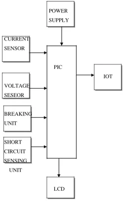
The power supply is provided using step-down transformer, rectifier, and regulator. The current sensing circuit of
the cable provides the magnitude of voltage drop across the resistors to the microcontroller and based on the voltage
6. BLOCK DIAGRAM
POWER
SUPPLY
CURRENT
SENSOR
PIC
IOT
VOLTAGE
SESEOR
BREAKING
UNIT
SHORT
CIRCUIT
SENSING
UNIT
LCD
Fig 1.1: Block Diagram of fault detection system
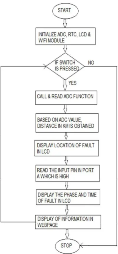
7. FLOW CHART
The input and output ports of Microcontroller, LCD display, RTC and Wi-Fi module of the system are configured
and initialized. When fault occurs (switch is pressed), the fault distance, time and phase are displayed
corresponding to that fault. The above fault information will be displayed in the webpage using Wi-Fi module.
8. INTERNET OF THINGS
The evaluation of IOT in the electrical Power Industry transformed the way things performed in usual manner. IOT
increased the use of wireless technology to connect power industry assets and infrastructure in order to lower the
power consumption and cost. The applications of IOT are not limited to particular fields, but span a wide range of
applications such as energy systems, homes, industries, cities, logistics, heath, agriculture and so on. Since 1881,
the overall power grid system has been built up over more than 13 decades, meeting the ever increasing demand for
digest the fact that power generated is not equal to the power consumed at the end point due to various losses. It is
even harder to imagine the after effects without power for a minute. Power outages occur as result of short circuits.
This is a costly event as it influences the industrial production, commercial activities and consumer lifestyle.
Government & independent power providers are continuously exploring solutions to ensure good power quality,
maximize grid uptime, reduce power consumption, increase the efficiency of grid operations and eradicate outages,
power loss & theft.
Figure 1.2: Logic behind the fault detection system
Most importantly, the solution should provide a real-time visibility to customers on every penny paid for their
energy. There is an increasing need of a centralized management solution for more reliable, scalable, and
manageable operations while also being cost effective, secure, and interoperable. In addition, the solution should
growing need for uninterrupted quality power. The goal of IOT is not just only connecting things such as machines,
devices and appliances, but also allowing the things to communicate, exchanging control data and other necessary
information while executing applications. It consists of IOT devices that have unique identities and are capable of
performing remote sensing, monitoring and actuating tasks. These devices are capable of interacting with one
another directly or indirectly. Data collection is performed locally or remotely via centralized servers or cloud
based applications. These devices may be data collection devices to which various sensors are attached such as
temperature, humidity, light, etc., or they may be data actuating devices to which actuators are connected, such as
relays.
IOT system is composed of three layers: the perception layer, the network layer, and the application layer as shown
in Figure 1.3.The perception layer includes a group of Internet-enabled devices that can percept, detect objects,
collect systems information, and exchange information with other devices through the Internet communication
networks. Sensors, Global Positioning Systems (GPS), cameras, and Radio Frequency Identification Devices
(RFID) are examples of devices that exist at perception layer. The network layer is responsible of forwarding data
from perception layer to the application layer under the constraints of devices’ capabilities, network limitation and the applications’ constraints. IOT systems use a combination of Internet and short-range networks based on the
communicated parties. Short-range communication technologies such as Bluetooth and ZigBee are used to carry
the information from perception devices to a nearby gateway. Other technologies such as Wi-Fi, 2G, 3G, 4G, and
Power line Communication (PLC) carry the information for long distances based on the application. The upper
layer is the application layer, where incoming information is processed to induce insights for better power’s
distribution design and management strategies.
Fig1.3: Architecture of IOT
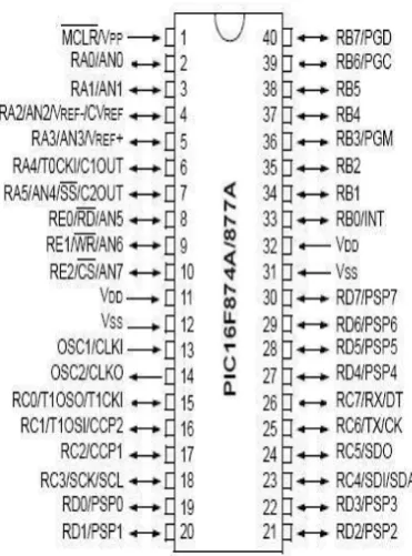
9. PIC MICROCONTROLLER
PIC (usually pronounced as "pick") is a family of microcontrollers made by Microchip Technology, derived from
parts of the family were available in 1976 by 2013 the company had shipped more than twelve billion individual
parts, used in a wide variety of embedded systems. Early models of PIC had read-only memory (ROM) or
field-programmable EPROM for program storage, some with provision for erasing memory. All current models use
flash memory for program storage, and newer models allow the PIC to reprogram itself. Program memory and data
memory are separated. Data memory is 8-bit, 16-bit, and, in latest models, 32-bit wide. Program instructions vary
in bit-count by family of PIC, and may be 12, 14, 16, or 24 bits long.
Fig 1.4: PIC Microcontroller
9.1. Long Word Instructions
Long word instructions have a wider (more bits) instruction bus than the 8-bit Data Memory Bus. This is possible
because the two buses are separate. This further allows instructions to be sized differently than the 8-bit wide data
word which allows a more efficient use of the program memory, since the program memory width is optimized to
the architectural requirements.
9.2. Single Word Instructions
Single Word instruction opcodes are 14-bits wide making it possible to have all single word instructions. A 14-bit
wide program memory access bus fetches a 14-bit instruction in a single cycle.
With single word instructions, the number of words of program memory locations equals the number of
instructions for the device. This means that all locations are valid instructions. Typically in the von Neumann
architecture, most instructions are multi-byte. In general, a device with 4-KBytes of program memory would allow
approximately 2K of instructions. This 2:1 ratio is generalized and dependent on the application code. Since each
instruction may take multiple bytes, there is no assurance that each location is a valid instruction.
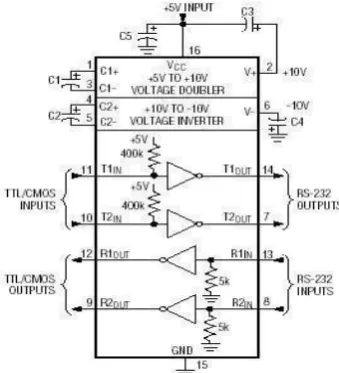
10. MAX 232- SERIALPORT INTERFACE
Fig 1.5: PINOUT DIAGRAM OF MAX232
The MAX232 is an integrated circuit first created in 1987 by Maxim Integrated Products that converts signals from
a TIA-232(RS-232) serial port to signals suitable for use in TTL-compatible digital logic circuits. The MAX232 is
a dual transmitter/dual receiver that typically issued to convert the RX, TX, CTS, RTS signals. The drivers provide
TIA-232 voltage level outputs (about±7.5volts) from a single 5-volt supply by on-chip charge pump sand external
capacitors. This makes it useful for implementing TIA-232 in devices that otherwise do not need any other
voltages. The receivers reduce TIA-232 inputs, which may be as high as ±25 volts, to standard 5volt TTL levels.
These receivers have a typical threshold of 1.3volts and a typical hysteresis of 0.5volts. The MAX232 replaced an
older pair of chips MC1488 and MC1489 that performed similar RS-232 translation. The MC1488 quad-transmitter
chip required 12 volt and-12 volt power, and MC1489 quad receiver chip required 5 volt power.
The voltage sensor is a device that coverts voltage measured between two points of an electrical circuit into a
physical signal proportional to the voltage. Implementation of voltage and current sensor techniques has become an
excellent choice to the conventional current and voltage measurements.
12. CURRENT SENSOR
Current sensor is device that detects electric current(AC or DC) in a wire that generates a signal proportional to it.
The generated signal could be analog voltage or current or even digital output. It can be then utilized to display the
measured current in an ammeter or can be stored for further analysis in a data acquisition system or can be utilized
for control purpose.
13. STANDARD SERIAL INTERFACE
The serial port is full duplex, meaning it can transmit and receives simultaneously. It is also receive-buffered,
meaning it can commence reception of a second byte before a previously received byte has been read from the
register. (However, if the first byte still hasn’t been read by the time reception of the second byte is complete, one of
the bytes will be lost.) The serial port receive and transmit registers are both accessed at Special Function Register
SBUF. Writing to SBUF loads the transmit register, and reading SBUF accesses a physically separate receive
register.
14. CONCLUSION
The short circuit fault at a particular distance in the underground cable is located to rectify the fault efficiently using
simple concepts of Ohms law. The work automatically displays the phase, distance and time of occurrence of fault
with the help of PIC 16F877A and ESP8266 Wi - Fi module in a webpage. The benefits of accurate location of fault
are fast repair to revive back the power system, it improves the system performance, it reduce the operating expense
and the time to locate the faults in the field.
REFERENCES
[1] Nikhil Kumar Sain, Rajesh Kajla, Mr.Vikas Kumar ―Underground Cable Fault Distance Conveyed Over
GSM‖ , http:// www.iosrjournals.org /2016/volume-11/ e-ISSN: 2278-1676,p-ISSN: 2320-3331, Volume
11, Issue 2 Ver. III (Mar. – Apr. 2016), PP 06-10.
[2] R.K.Raghul Mansingh, R.Rajesh, S.Ramasubramani, G.Ramkumar,―Underground Cable Fault
Detection using Raspberry Pi and Arduino‖, http://www.ijeter.everscience.org/International Journal of
Emerging Technologies in Engineering Research (IJETER) , Volume 5, Issue 4, April (2017).
[3] Mane Tejasri, Pawar Prajakta, Sabale Nayan―Underground Cable Fault Detection.‖, http://
www.ierjournals.org/InternationalEngineeringResearch Journal (IERJ) /Volume 2/ Issue 2/ Page 417-419,
[4] Swapnil Gaikwad, Hemant Pawar, Ajay Jadhav, Vidhut Kumar―UNDERGROUND CABLE FAULT
DETECTION USING MICROCONTROLLER‖, IJARIIE-ISSN(O)-2395-4396, Vol-2 Issue-3 2016.
[5] Akash Jagtap, Jayesh Patil, Bhushan Patil, Dipak Patil, Aqib Al Husan Ansari ―Arduino based
Underground Cable Fault Detection‖, International Journal for Research in Engineering Application &
Management (IJREAM) ISSN : 2454-9150 Vol-03,Issue 04, May 2017.
[6] Dhivya Dharani.A, Sowmya.T ―Development of a Prototype Underground Cable Fault Detector‖,
International Journal of Electrical, Electronics and Computer Systems (IJEECS), ISSN (Online):
2347-2820, Volume -2, Issue-7, 2014.
[7] V. Kirubalakshmi, C. Muthumaniyarasi―IOT Based Underground Cable Fault Detector. Volume 8, Issue
8, August 2017, pp. 1299–1309, Article ID: IJMET_08_08_132, ISSN Print: 0976-6340 and ISSN Online: