paper. High voltage gains are obtained by employing a coupled inductor with same primary and secondary winding turns in the converter. Beside from high voltage gain, its average value of switch current and voltage stress on switches are lower compared to conventional dc-dc converter. The steady state analysis and operating principles in continuous conduction mode are discussed. Pulse width modulation (PWM) is used to control the switches. To study the performance of the proposed converter, simulations has been carried out in MATLAB2010 environment. Feedback is also given to the circuit using a pi controller and relational operator to get a constant output voltage for such applications.
Keywords:-Bidirectional dc-dc converter, coupled inductor, PWM.
I.
INTRODUCTION
A DC-DC converter is an electronic circuit which converts a source of direct current from one voltage level to another. It is a class of power converter[11]. Bidirectional DC-DC converters has the ability to direct the current flow in both direction and thereby power. It is increasingly used to transfer power in either direction between the dc sources. These converters has become an option in applications including hybrid vehicle energy system [1]-[3], fuel cell vehicles [9], battery chargers [13] etc.
Most of the existing dc-dc converters can be categorized based on placement of energy storage as buck and boost types. In buck type, it is on high voltage side energy storage is placed and in boost type, it is on low voltage side. For isolated bidirectional dc-dc converters, sub topology is full bridge, a half bridge, a push pull circuit or their variations [9], [20]. In these converters, for operation it utilizes the leakage inductance of transformer as the main element. The half bridge types will have a higher efficiency and will reduce the device count. The full bridge types is one of the choices. But the configuration is complex and large in size and cost is high. Conventional boost/buck [1], multilevel [4], three level, sepic/zeta, switched capacitor and coupled inductor types are there in non-isolated dc-dc converters. Transformer based system is attractive, but its weight or size is a concern in the case of space craft power system applications. So transformer less is more used in high power applications. To increase the density of power, multiphase current interleaving technology with low inductance is used in high power applications. It is having better efficiency. In a three phase dc-dc converters, ripple on total current is small and low value of capacitance is used in both high and low voltage sides. Electronic switch mode dc-dc converter will convert one voltage dc level to another. The half bridge and fly back topologies are similar. Both stored energy in the magnetic core needs to be dissipated. Switched capacitor types used at high voltages applications. It will provide high step-up and step-down voltage gains as coupled inductor types.
Fig.1 Proposed bidirectional dc-dc converter
II.
COUPLED INDUCTOR
Fig. 2 Coupled inductor
Two inductors or coils that are linked by electromagnetic induction are said to be coupled inductors. The phenomenon of one inductor inducing a voltage in another inductor is mutual inductance. Circuits which contain coupled inductor are more complicated because the voltage of the coils are expressed in terms of their
current. Three parameters are required to characterize a pair of coupled inductor: two self-inductances, L1 and L2
and the mutual inductance, M. Since the coupled inductor has same turns in the primary and secondary windings, the inductance in the primary and secondary will be same and can be expressed as
L1 = L2 = L. (1)
Thus, M the mutual inductance of the coupled inductor is M=KL. (2)
Where K, is the coupling coefficient of the coupled inductor. Coupling coefficient, K is typically around
0.95.The voltage across primary and secondary windings of the coupled inductor are
𝑉𝐿1 = 𝐿2 𝑑𝑖𝐿1
𝑑𝑡 + M 𝑑𝑖𝐿2
𝑑𝑡 = 𝐿 𝑑𝑖𝐿1
𝑑𝑡 + 𝐾𝐿 𝑑𝑖𝐿2
𝑑𝑡 .
(3)
𝑉𝐿2 = 𝐿2 𝑑𝑖𝐿2
𝑑𝑡 + M 𝑑𝑖𝐿1
𝑑𝑡 = 𝐿 𝑑𝑖𝐿2
𝑑𝑡 + 𝐾𝐿 𝑑𝑖𝐿1
𝑑𝑡 . (4)
III.
STEP – UP MODE
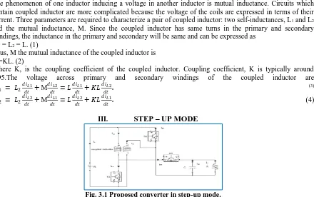
Fig. 3.1 Proposed converter in step-up mode.
The proposed converter in step-up mode[1] is shown in Fig.3.1.The pulse width modulation (PWM)technique is used to control the switches S1, S2 and S3. The operating principles and steady state analysis of continuous conduction mode is described as follows.
1) Mode 1:During this time interval (DTs), switches S1 and S2 are turned ON and switch S3 is turned
OFF. The current flow path is shown in Fig. 3.2(a). The energy in the low voltage side VL is transferred to the
primary and secondary windings of the coupled inductor. That time the primary and secondary windings are in
𝑑𝑡 = 𝑑𝑡 = 2 1+𝐾 𝐿 . for the period (1-D) Ts. (9)
From (6) and (9):
𝐷𝑉𝐿
1+𝐾 𝐿+
(1−𝐷)(𝑉𝐿−𝑉𝐻)
2 1+𝐾 𝐿 = 0 . (10)
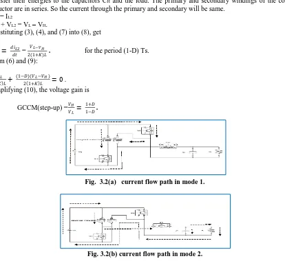
Simplifying (10), the voltage gain is
GCCM(step-up) =𝑉𝐻
𝑉𝐿 =
1+𝐷
1−𝐷 . (11)
Fig. 3.2(a) current flow path in mode 1.
Fig. 3.2(b) current flow path in mode 2.
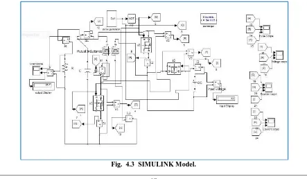
a) SIMULINK Model
Simulation has been carried out to study the performance of a proposed bidirectional dc-dc converter.
A low voltage of 14V is given as input voltage. Three switches S1, S2 and S3 are controlled by PWM technique.
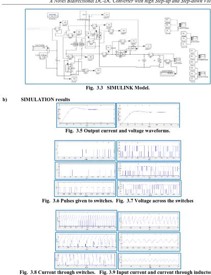
Fig. 3.3 SIMULINK Model.
b) SIMULATION results
Fig. 3.5 Output current and voltage waveforms.
Fig. 3.6 Pulses given to switches. Fig. 3.7 Voltage across the switches
Fig. 3.8 Current through switches. Fig. 3.9 Input current and current through inductors.
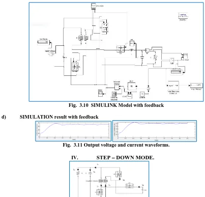
c) SIMULINK Model With Feedback
Fig. 3.10 SIMULINK Model with feedback
d) SIMULATION result with feedback
Fig. 3.11 Output voltage and current waveforms.
IV.
STEP – DOWN MODE.
Fig. 4.1 Proposed converter in step-down mode.
The proposed converter in step-down mode[1] is shown in Fig. 4.1.The pulse width modulation (PWM) technique is used to control the switches S1, S2 and S3. The operating principles and steady state analysis of
continuous conduction mode is described as follows.
1) Mode 1: During this time interval (DTs), Switch S3 is ON and switches S1, S2are OFF. The current
flow path is shown in Fig. 4.2(a). The high voltage side VH energy is transferred to the primary and secondary of
the coupled inductor, the capacitor CL and the resistive load. At this time the primary and secondary windings of
the coupled inductor are in series. The current through the primary and secondary are equal and are given as:
IL1 =IL2 (12)
VL1 + VL2 = VH – VL. (13)
Substituting (3), (4), (12) into (13), get
𝑑𝑖𝐿1
𝑑𝑡 = 𝑑𝑖𝐿2
𝑑𝑡 = 𝑉𝐻 −𝑉𝐿
2 1+𝐾 𝐿For the period DTs. (14)
2) Mode 2:During this time interval (1-DTs), switch S3 is turned OFF and switches S1, S2 are ON. The
current flow path is shown in Fig. 4.2(b). The energy stored in the primary and secondary windings of the
coupled inductor will flow to the capacitor CL and the resistive load. The primary and secondary windings of the
coupled inductor are coming in parallel. The voltage across the primary and secondary windings are
VL1 = VL2 = -VL. (15)
Substituting (3) and (4) into (15),
𝑑𝑖𝐿1 𝑑𝑡 =
𝑑𝑖𝐿2 𝑑𝑡 = −
𝑉𝐿
From (14) and (16):
𝐷(𝑉𝐻−𝑉𝐿)
2 1+𝐾 𝐿 − 1−𝐷 𝑉𝐿
1+𝐾 𝐿 = 0. (17)
Simplifying (17), the voltage gain is
𝐺𝐶𝐶𝑀(𝑠𝑡𝑒𝑝 −𝑑𝑜𝑤𝑛 )= 𝑉𝐿
𝑉𝐻=
𝐷
2−𝐷 . (18)
Fig. 4.2(a) current flow path in mode 1.
Fig. 4.2(b) current flow path in mode 2.
a) SIMULINK Model.
Simulation has been carried out to study the performance of a proposed bidirectional dc-dc converter.
A high voltage of 42V is given as input voltage. Three switches S1, S2 and S3 are controlled by PWM technique.
Fig. 4.4 Output current and voltage waveforms.Fig. 4.6 Voltage across switches.
Fig. 4.7 Current through switches. Fig. 4.8 Current through coupled inductor and output current.
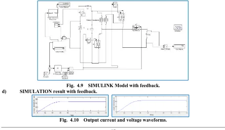
c) SIMULINK Model With Feedback
With a resistive load the output voltage will be pulsating. For a constant voltage application, the voltage is to be constant. To achieve this a feedback circuit is given to the Simulink model Fig. 4.9. In the PI controller, the values of Kp is 0.006 and Ki is 36.38 approximately. Here also the total harmonic distortion is measured and it is reduced to 0.0667 value when a filter is given.
Fig. 4.9 SIMULINK Model with feedback. d) SIMULATION result with feedback.
V.
PROPOSED CONVERTER VS CONVENTIONAL BIDIRECTIONAL DC-DC
CONVERTER.
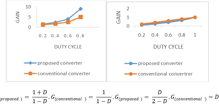
A. Voltage Gain
For various values of duty cycle D, calculate voltage gain G and the graph is plotted. The voltage gain curve for proposed converter and conventional converter in continuous conduction mode of operation are plotted[1] in such a way in Fig. 5.1. From the graph we can conclude that the voltage gain in up and step-down operations of the proposed converter are higher.
𝐺(𝑝𝑟𝑜𝑝𝑜𝑠𝑒𝑑 )=
1 + 𝐷
1 − 𝐷. 𝐺(𝑐𝑜𝑛𝑣𝑒𝑛𝑡𝑖𝑜𝑛𝑎𝑙 )= 1
1 − 𝐷. 𝐺(𝑝𝑟𝑜𝑝𝑜𝑠𝑒𝑑 )= 𝐷
2 − 𝐷. 𝐺(𝑐𝑜𝑛𝑣𝑒𝑛𝑡𝑖𝑜𝑛𝑎𝑙 )= 𝐷.
Fig. 5.2 Voltage gain of the proposed converter in step-up and down mode.
B. Voltage Stress on the Switches.
From the waveforms Fig. 3.7 and Fig. 4.6, the voltage stresses on switches S1, S2 and S3 in the proposed
converter are VDS1 = VDS2 =
𝑉𝐻+𝑉𝐿
2 (19)
VDS3 = VH+VL (20)
In the conventional bidirectional dc-dc converter the voltage stress on switches S1 and S2 are
VDS1 = VDS2 = VH. (21)
Therefore, the rated voltage of switches S1 and S2 can be selected lower in the proposed converter than
the conventional converter if the proposed converter is using for an application with high step-up and step-down
voltage gain. And the rated voltage of switch S3 can be selected as same in both proposed and conventional
converters.
C. Average value of the Switch- Current
The average value of input current IL can be found[1] from the Fig. 3.9, when the proposed converter is
operated in continuous conduction mode in step-up mode
𝐼𝐿(𝑝𝑟𝑜𝑝𝑜𝑠𝑒𝑑 )=
2𝐼𝐿1 𝑝𝑟𝑜𝑝𝑜𝑠𝑒𝑑 𝐷𝑇𝑠 + 𝐼𝐿1 𝑝𝑟𝑜𝑝𝑜𝑠𝑒𝑑 1 − 𝐷 𝑇𝑠
𝑇𝑠
= (1+D)𝐼𝐿1(𝑝𝑟𝑜𝑝𝑜𝑠𝑒𝑑 ). (22)
The average value of the input current IL when the conventional bidirectional converter is operated in step-up modein continuous conduction mode is
𝐼𝐿(𝑐𝑜𝑛𝑣𝑒𝑛𝑡𝑖𝑜𝑛𝑎𝑙 )= 𝐼𝐿1 𝑐𝑜𝑛𝑣𝑒𝑛𝑡𝑖𝑜𝑛𝑎𝑙 . (23)
The input power for same electric specifications for proposed and conventional converter is given by
𝑃𝑖𝑛 = 𝑉𝐿𝐼𝐿(𝑐𝑜𝑛𝑣𝑒𝑛𝑡𝑖𝑜𝑛𝑎𝑙 )= 𝑉𝐿𝐼𝐿 𝑝𝑟𝑜𝑝𝑜𝑠𝑒𝑑 . (24)
Substitute (22) and (23) into (24), we get
𝐼𝐿1(𝑝𝑟𝑜𝑝𝑜𝑠𝑒𝑑 )=
𝐼𝐿1(𝑐𝑜 𝑛𝑣𝑒𝑛𝑡𝑖𝑜𝑛𝑎𝑙 )
1+𝐷 . (25)
0 5 10
0 . 2 0 . 4 0 . 6 0 . 8
G A IN DUTY CYCLE proposed converter conventional converter 0 1 2
0.2 0.4 0.6 0.8 1
G
AIN
DUTY CYCLE
proposed converter
From (25) and (28), we can understand that the average value of switch current in the proposed converter is less than the conventional bidirectional converter.
VI.
CONCLUSION
A bidirectional dc-dc converter with a coupled inductor is presented in this paper. The proposed converter is having a simple circuit configuration. The operating principles and steady state analysis of the proposed converter is also explained in this paper.The proposed converter is having a high voltage gain in step-up and step-down modes than a conventional converter. The average value of switch current in the proposed converter is less than the conventional converter. The rated voltage of the switches in the proposed converter can be selected to be lower in high voltage gain applications also. From the simulation results, it is see that the waveforms agree with the operating principles and steady state analysis.
REFERENCES
[1]. Lung-Sheng Yang and Tsorng-Juu Liang, ―Analysis and Implementation of a Novel Bidirectional
DC-DC Converter,‖ IEEE Trans. Ind. Appl., vol. 59, no. 1, pp. 422-434, Jan. 2012.
[2]. M. B. Camara, H. Gualous, F. Gustin, A. Berthon, and B. Dakyo, ―DC/DC converter design for
supercapacitor and battery power management in hybrid vehicle applications—Polynomial control strategy,‖ IEEE Trans. Ind. Electron., vol. 57, no. 2, pp. 587–597, Feb. 2010.
[3]. T. Bhattacharya, V. S. Giri, K. Mathew, and L. Umanand, ―Multiphase bidirectional flyback converter
topology for hybrid electric vehicles,‖ IEEE Trans. Ind. Electron., vol. 56, no. 1, pp. 78–84, Jan. 2009.
[4]. Z. Amjadi and S. S. Williamson, ―A novel control technique for a switched-capacitor-converter-based
hybrid electric vehicle energy stor- age system,‖ IEEE Trans. Ind. Electron., vol. 57, no. 3, pp. 926– 934, Mar. 2010.
[5]. F. Z. Peng, F. Zhang, and Z. Qian, ―A magnetic-less dc–dc converter for dual-voltage automotive
systems,‖ IEEE Trans. Ind. Appl., vol. 39, no. 2, pp. 511–518, Mar./Apr. 2003.
[6]. F. Z. Peng, H. Li, G. J. Su, and J. S. Lawler, ―A new ZVS bidirectional dc–dc converter for fuel cell
and battery application,‖ IEEE Trans. Power Electron., vol. 19, no. 1, pp. 54–65, Jan. 2004.
[7]. K. Jin, M. Yang, X. Ruan, and M. Xu, ―Three-level bidirectional converter for fuel-cell/battery hybrid
power system,‖ IEEE Trans. Ind. Electron., vol. 57, no. 6, pp. 1976–1986, Jun. 2010.
[8]. S. Inoue and H. Akagi, ―A bidirectional dc–dc converter for an energy storage system with galvanic
isolation,‖ IEEE Trans. Power Electron., vol. 22, no. 6, pp. 2299–2306, Nov. 2007.
[9]. F. Zhang and Y. Yan, ―Novel forward-flyback hybrid bidirectional dc–dc converter,‖ IEEE Trans. Ind.
Electron., vol. 56, no. 5, pp. 1578–1584, May 2009.
[10]. H. Li, F. Z. Peng, and J. S. Lawler, ―A natural ZVS medium-power bidirectional dc–dc converter with
minimum number of devices,‖ IEEE Trans. Ind. Appl., vol. 39, no. 2, pp. 525–535, Mar. 2003.[11] L. S. Yang, T. J. Liang, and J. F. Chen, ―Transformerless dc–dc converters with high step-up voltage gain,‖ IEEE Trans. Ind. Electron., vol. 56, no. 8, pp. 3144–3152, Aug. 2009.