Abstract—In geomechanics, the knowledge and the
characterization of the in situ stress state is required for applications encountered in Rock Mechanics; it may be obtained by measuring the strain response of the ground under the effect of a known stress. Actually, several technics have been developed to estimate the in-situ stresses. Among these methods, we are particularly interested in the overcoring test, which consists of measuring displacements and deformations generated to the borehole walled after the relaxation involved in the drilling of a coaxial ring. If the rock model behavior is irreversible, thus, the interpretation of overcoring test becomes delicate. The analysis presented in this document is devoted to the direct problem. The tridimensional modelling is used taking into account the drill progress. In this work, the process used in the overcoring test of elastoplastic isotropic rock is analyzed by a numerical approach, by using a tridimensional modelling via the perfect elastoplastic model of Drucker-Prager without hardening. The strains studied correspond to those given by the cell CSIRO gauges (Worotnicki and al, 1976). The tridimensional study put in evidence the difference in the time for the cases of hydrostatic and deviatoric loading.
Index Terms—Stress, overcoring, tridimensional modelling,
numerical simulation, elastoplastic medium.
I. INTRODUCTION
In the design and implementation of projects, knowledge of natural constraints in the basement is a very important element in the field of civil engineering as well as in the mining or energy basement. Numerical modeling tools have been effectively developed, but paradoxically, knowledge of constraints introduced in these models is still quite shallow. One of the reasons is the difficulty and the high cost to determine the in-situ natural constraints. Their determination is assigned to a scale effect; also the variability within the massif complicates oddly the interpretation of measurements. The Overcoring technique works to measure deformations generated to the walls of a borehole after the relaxation involved by the drilling of a coaxial ring.
Knowing the deformations in twelve (12) directions and from a number of assumptions and the determination of some mechanical parameters we are able to estimate a stress tensor. Manuscript received October 31, 2012; revised November 30, 2012. This work was supported in part by the L.E.E.G.O. Laboratory of Environment, Water, Geomechanics and Structures and the U.S.T.H.B. Faculty of Civil Engineering at the University of Science and Technology Houari Boumediene, USTHB, Algeria.
The authors are with the Laboratory of Environment, Water, Geomechanics and Structures (LEEGO), Algeria.& Faculty of Civil Engineering, University of Science and Technology Houari Boumediene, USTHB, Algiers, Algeria (e-mails: [email protected], [email protected]).
II. DESCRIPTION OF THE OVERCORING TECHNIC
A. The Overcoring
The overcoring is a technical measuring of the stress state in rock formations and elsewhere in the concrete. The overcoring test consists of positioning a measuring cell in a drilled hole until the desired point where we wish to know the stress state then performing a bleeding by drilling, where, the volume of rock such delimited and containing the measuring cell is free of the enclosed stresses [5].
The difference between the deformation recording by the cell before and after the overcoring provides thereafter the access to the initial stress state prevailing in the considered rock volume under the appropriate assumption of the behavior laws.
Among the instruments, or cells, allowing the realization of these measures which have been developed and tested during the 60s, we are particularly interested by the triaxial cell which is developed by the CSIRO (Commonwealth Scientific and Industrial Research Organization) [4].
B. Description of the Cell C. S. I. R. O.
The cell C.S.I.R.O. has twelve (12) gauges rosettes divided in three (3) groups, fixed to the cylindrical cell body as shown in the Fig. 1:
Fig. 1. CSIRO cell geometry [5].
05 gauges inclined at 45 ° relative to the borehole axis
Tridimensional Numerical Contribution of Displacements
Evolution in a Rock Subjected to A Deviatoric Loading
Using Overcoring Test
05 tangent gauges (or cylindrical) 02 axial gauges
III. PRESENTATION OF THE INVERSE PROBLEM THEORY The direct problem is to fix the initial constraints sought, and then simulate numerically the overcoring test, knowing the rheology of the rock; we get the results of the deformations or displacements. The inversion of these results allows us to trace the initial stresses prevail in the rock.
IV. PRESENTATION OF THE ORIGINALLY OF STUDY MATERIAL
To investigate the possibility of burying radioactive waste in deep geological formations, conducted by ANDRA (National Agency for Radioactive Waste Management In), a testing program was carried out in situ in a potash mines gallery of Alsace (MDPA) in the basin potash Mulhouse [6].
V. INITIAL STRESSES
The initial state of stress is characterized by the major and the minor principal stresses, where, their principal directions are orthogonal to the borehole axis (Y) and the initial stress
σz.init; this latest stress is arbitrary fixed. The parametric study
will be done on the variation of stresses σh and σH.
K = H h
(1)
The ratio K is called "anisotropic ratio", it characterizes the initial state of stress: K = 1 which corresponds to the case of plane hydrostatic initial stresses (
z.init
= h =H). A high value of K corresponds to the initial stress strongly deviatoric.
The behavior model which is considered (negative compressions) is function of the deviatoric stress state D9 (σH = - 36 MPa, σh = - 12 MPa, σv = σz.init= -30 MPa), with an
anisotropic ratio K = 3 has been considered systematically for the perfect elastoplastic model of Drucker-Prager and the linear elastic model to a major initial stress level H (- 36 MPa).
VI. DEVELOPMENT OF THE TRIDIMENSIONAL MODEL
A. Assumptions and Mesh
Overcoring procedure in an isotropic rock is numerically modelled, using a tridimensional modelling. It is possible to follow the evolution of the deformation of the twelve gauges composing the CSIRO cell. The simulation is done by using the CESAR LCPC software and its new pre-processor CLEO 3D standard 4.0.7.
In this study, we are interested in cases where the behavior of the rock is elastoplastic isotrope, depending on the perfect elastoplastic model of Drucker-Prager without hardening. The tridimensional calculation with the isotropy plan emerged with the core axis (forming an angle of 0°) is performed with a hydrostatic initial stress state and two
deviator initial stresses state. Assuming that the initial state of stress is constant for a given medium, the dimensions chosen for the model are 1000 mm wide, 1000 mm high and 1300 mm length (see Fig. 2-a), where:
The Bore hole: 38 mm, with 700 mm length along the Y axis,
Hole of overcoring: internal and external diameters are =142 mm and 160 mm respectively with 700 mm length in the direction of Y axis.
Width of the groove is 9 mm.
(a)
(b)
Fig. 2. (a): Model size and imposed displacements perpendicular to facets [3]- (b): Full mesh [7].
The boundary conditions of the model were fixed so that the variation of deformation or displacement as a result of the successive phases of coring or overcoring becomes negligible. [3].
The final mesh consists of sixteen blocks or sub-structures, including fourteen were used to modelling the advancement of the core barrel during the phase overcoring. The two other correspond to the blocks before and after the coring (Fig. 2-b).
The imposed loading is determined by:
The initial major stress σH = σ1 in the X axis direction,
The initial minor stress σh = σ2 in the Z axis
Average stress σz, moy = σ3 in the direction of Y axis (the
borehole axis)
B. Calculation Method
An initialization step of the initial stress field prevailing in the rock before the procedures of coring and overcoring,
A step corresponding to the phase of coring,
The remaining fourteen computation steps corresponding to the advancement of the core barrel at the overcoring phase.
All these calculations are performed with recovery, ie the state of stress and strain at the end of step i
corresponds to the same state at the beginning of step
i+1.
VII.RESULTS AND DISCUSSIONS
The objective of this study is to verify that, for similar problems, the predicted displacements of the two models, the linear elastic isotropic and the elastoplastic model of Drucker-Prager without hardening, are reasonably close to the theoretical results or to those performed in situ.
A. Linear Elastic Isotropic Behavior
Evolution of elastic displacements depending on the progress of the core barrel
It is concluded a perfect resemblance between the evolution of the elastic displacement “w” due to a circular
gauge A90 according to the progress of the core barrel (Fig. 3) and that estimated by (Nechnech,1998) refer to the (Fig. 4). It is distinguished the same bearings, a bearing rest between the beginning and the end of the first phase (from 0 to 145mm of overcoring), then a slight compression before the influence area starting from 145 to 343 mm and a subsequent sudden variation around of the measuring cell between 343 and 400 mm with a slight compression after the influence area. Afterwards, the curve stabilized at the end of the last bearing of overcoring between 435 and 700 mm.
Fig. 3. Evolution of displacement “w” (mm) of circular gauge A90
depending on the progress of the core barrel, (Elastic model of Drucker-Prager): Isotropic material, deviatoric state of stress D9 [7].
Evolution of the plastic deformation norm NDP depending on the progress of the core barrel
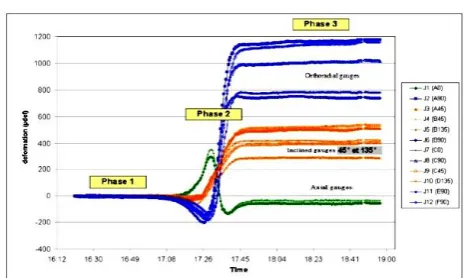
By comparing the evolution in the variation of plastic deformation norm NDP of the circular gauge A90 depending of the progress of the core barrel (Fig. 5) and the real responses of tangential gauges according the progress of the core barrel during the overcoring process developed by the INERIS team in 2010 (Fig. 6).
Fig. 4. Evolution of the deformation depending on the position of the core barrel (Elastic model of Drucker-Prager): Isotropic material, deviatoric state
of stress (Nechnech, 1998) D9 [2].
Evolution of the plastic deformation norm NDP depending on the progress of the core barrel
By comparing the evolution in the variation of plastic deformation norm NDP of the circular gauge A90 depending of the progress of the core barrel (Fig. 5) and the real responses of tangential gauges according the progress of the core barrel during the overcoring process developed by the INERIS team in 2010 (Fig. 6).
Fig. 5. Variation of the plastic deformation norm NDP of a circular gauge A90 depending on the progress of the core barrel, elastoplastic model of
Drucker-Prager, deviatoric state of stress D9 [7].
Fig. 6. Overcoring test; Typical curves of deformations obtained in the clay stone of Tournemire. [INERIS report – DRS-10-97197-04334A: Lahaie,
2010]. (Ben Ouenass A. 2010) [1].
The appearance of the NDP curve is characterized by two bearing, the first one from 0 to 145 mm and the second between 435 and 700 mm, they correspond to the beginning and at the end of overcoring process. Between the two 0,00E+00
5,00E-03 1,00E-02 1,50E-02 2,00E-02 2,50E-02
0 100 200 300 400 500 600 700 800 Avancement du carottier L (mm)
W A90
A90
3,1000E-03 3,2000E-03 3,3000E-03 3,4000E-03 3,5000E-03 3,6000E-03 3,7000E-03
0 100 200 300 400 500 600 700 800 Avancement du carottier L (mm)
NDP A90
B. Elastoplastic Behavior
bearings is defined an area called influence zone. This influence zone is formed by a small compression (or expansion depending of the considered gauge) before and after the central part. By-the other hand, by a linear variation rapid (sudden) corresponds to the overcoring at the position of measuring gauges. So we can conclude that the response of the NDP circular gauge A90 in the Fig. 5 looks like to the curve in the Fig. 6) established by INERIS (2010), this is the same for all gauges.
However, in the theory of elastoplasticity, the total strain is defined as the sum of a reversible deformation (elastic) and irreversible deformation (plastic).
e p
(2)Evolution of elastoplastic displacements depending on the progress of the core barrel
In the case of elastoplasticity, the responses of displacements u and w of all gauges have the same characteristics and the same path and curvatures according to the progress of the core barrel during the overcoring steps (Fig. 7 and 8 below).
It is also observed a regression of curves at the left, before the positioning zone of the cell, which means that there is a disturbance on the responses of recorded displacements. This is due to high plasticization in the beginning of the overcoring test and to compressive stresses variations near the measuring cell. This, concerns all the following gauges: A0, B45, C45, A90 and F90 tested in-situ (see the part elastoplastic of the curve of the Fig. 4).
The responses of the inclined gauges have a certain superposion as gauges (A45, C45) and (B45, B135) in pairs (Fig. 7). The slight difference is mainly due to the problem of symmetry of gauges. For example in the case of the rosette-gauge B we recorded negative values in Z axis of the local coordinate system instead of positive ones.
Fig. 7. Evolution of displacement w (mm) inclined gauges according to the progress of the core barrel: elastoplasticity linear isotropic loading deviatoric
D9 [7].
The circular gauge A90, represented by the variation of the displacement which depends of the progress of the core barrel (Fig. 8), almost looks like the real curve of tangential gauges elaborated by the INERIS team in 2010. This resemblance is characterized in the high compression observed at the beginning and the end of the influence zone (to the side of the location of the gauge see Fig. 6). On the other hand, the rapid variation of gauges which is quasi-linear represents a total relaxation of the rock.
Fig. 8. Evolution of displacement w (mm) gauge circular A 90 depending on the progress of the core barrel: elastoplastic material, deviatoric loading D9
[7].
At the end of the phase overcoring, all the curves representing the circular gauges are almost parallel to each other.
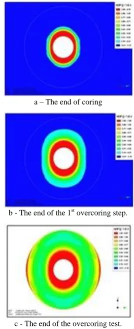
This is reflected by the high plasticization of the bore hole, as well as the replastification at the end of the first overcoring phases. This is caused by the high state of stress D9 which presents a very high anisotropic ratio (K = 3) see Fig. 8-a and 8-b.
The replastification increases gradually as the excavation of fourteen successive overcoring phases and it is important at the end of overcoring test (Fig. 8-c). This plasticizing undergone by the material during the coring is exerted differently depending on positions of the different points of the side of the borehole. This is relative to the associated directions of initial principal stresses.
a – The end of coring
b - The end of the 1st overcoring step.
c - The end of the overcoring test.
Fig. 9. (All a, b and c) Variation of isovalues of Standard Plastic Deformation NDP, State D9 (k = 3), elastoplastic Drucker-Prager [7]. -3,0000E-02
-2,5000E-02 -2,0000E-02 -1,5000E-02 -1,0000E-02 -5,0000E-03 0,0000E+00 5,0000E-03 1,0000E-02 1,5000E-02
0 100 200 300 400 500 600 700 800 Avancement du carottier L (mm)
W
(
m
m
)
B135 A45 C45 B45 D135
A90
-4,0000E-03 -2,0000E-03 0,0000E+00 2,0000E-03 4,0000E-03 6,0000E-03 8,0000E-03 1,0000E-02 1,2000E-02
0 100 200 300 400 500 600 700 800 Avancement du carottier L (mm)
W
(
m
m
)
VIII. CONCLUSION
The responses of gauges depending on the progress of the core barrel, after the influence area it is noted an increase or a decrease in amplitude depending on the gauge position. The response of the gauge will be stabilized in the end of overcoring.
The disturbance that occurs before the position of the measuring cell is the creation of the peak in the influence area due to large variations in compressive stresses which transformed to tensile stresses near the cell. Elsewhere, there is no peak in the elastic isotropic case, where the disturbance takes exactly place at the location of the cell.
The ratio K, "stress anisotropy," for a highly deviatoric loading D9 (k = 3) leads to a plasticization of all points of the corer, which is the highest around the principal minor stress. In addition, there is a replastification of the core barrel due to successive phases of overcoring excavations; this replastification becomes a double at the end of overcoring phase
.
REFERENCES
[1] A. B. Ouanas, “Interprétation de mesures de déformation en forage en terrain anisotrope: Retour d’expérience de l’utilisation de cellules CSIRO dans l’argilite de Tournemire (Aveyron),” Thèse de Doctorat. Université de Nancy, l'Institut National Polytechnique de Lorraine –LAEGO – I.N.P.L, 2010.
[2] A. Nechenech, “Modélisation numérique du problème du surcarottage: Influence de la loi de comportement de la roche,” Thèse de Doctorat de l'Institut National Polytechnique de Lorraine (I.N.P.L) –LAEGO. Ecole Nationale Supérieure de Géologie de Nancy – E.N.S.G.N, 1998. [3] G. Worotnicki, “Triaxial stress measurement cell,” Comprehensive Rock Engineering, Rock Testing and Site Characterisation. vol. 3, pp. 329-394. 1993.
[4] G. Worotnicki and R. J. Walton, “CSIRO triaxial stress measurement cell,” Proc. ISRM Symp on Investigation of Stress in Rock, Supplement, 1-8, Institution of Engineers Australia, Sydney. 1976.
[5] H. Baroudi and R. Revalor, “Descriptif des techniques de mesures de contraintes. Méthode de surcarottage, Suivi de l'évolution des contraintes. Séminaire de formation C.E.E.C. (programme COMETT),”
Mesure Des Sollicitations et Des Contraintes Dans Les Ouvrages et Les Terrains, École des Mines de Nancy. 12/16 septembre 1994. [6] K. B. Slimane, A. Cournut, J. F. D. Smet, and C. Trentesaux, “In situ
study and modeling of the mecanical behavior of a large diameter vertical blind hole in marl,” Int. Conf. on Deep Geological Disposal of Radioactive Waste, Winnipeg, pp.671-680, 1996.
[7] M. Chikhaoui, “Simulation numérique de la détermination des contraintes in situ dans un milieu élastoplastique – Modélisation tridimensionnelle,” Mémoire de Magister en génie civil. Spécialité: Géotechnique. Laboratoire LEEGO – Faculté de Génie Civil USTHB - Beb Ezzouar Alger, Algérie, 2009.
Chikhaoui Mohamedwas born on May 26th in 1976, at Ain-Defla, Algeria. Is currently an Assistant Professor at the Faculty of Civil Engineering, at the University of Sciences and Technology, Houari Boumediene, USTHB, Algeria. He is engineering civil engineering in 2001from the University of Sciences and Technology, Houari Boumediene, USTHB, Algeria. His main interests are in the field of geomechanics and geotechnical engineering. Member of the Laboratory of Environment, Water, Geomechanics and Structures (LEEGO)/USTHB
![Fig. 1. CSIRO cell geometry [5].](https://thumb-us.123doks.com/thumbv2/123dok_us/1364723.1645919/1.595.323.525.501.771/fig-csiro-cell-geometry.webp)
![Fig. 2. (a): Model size and imposed displacements perpendicular to facets [3]- (b): Full mesh [7]](https://thumb-us.123doks.com/thumbv2/123dok_us/1364723.1645919/2.595.319.524.101.525/fig-model-size-imposed-displacements-perpendicular-facets-mesh.webp)