Analysis of Thermodynamic refrigeration cycle:
Optimalisation of heat transfer rate by Pilot Control
Servo ICS Valve on Pulse Width Modulation Scheme
1
I Ketut Daging, Gunadi, Juniawan Preston Siahaan, Maimun, MH. Simanjuntak, Subroto Alirejo, Teguh Binardi,
Bambang Murtiyoso, Yusuf Syam, Basino, Ade Hermawan, Sobri, and
2Rahmad Surya HS
1 Department Fishing Technology, Faculty Fishery Machinery,
Jakarta Fisheries University, Jakarta, Indonesia; 2 Study Program of Capture Fisheries
Marine and Fisheries Polytechnic of Karawang, West Java, Indonesia
Abtract-- The Proper refrigerant flow settings can improve the overall efficiency of the system. On several refrigeration systems, the load will vary over a wide range, requiring the use of an evaporator heat transfer rate control, one of which is a pulse width modulation scheme. But the scheme faces many problems, as it often implies reliability issues. Some require technical skills to provide the level of efficiency or stability of the system originally assured. The ICS is an valve of Pilot control servo which work on an air conditioner system on vessel. ICS Pilot Control Servo setting is a regulator to set up the refrigerant flows which is certainly analyses through thermodynamic analysis due to a stability category experiment and instability of a refrigeration cycle to obtain the highest optimization value. The result on highest stablitiy by setting up ICS in suction parameter with low pressure between 4 – 6 kg/cm2 where shows 25 A
on electric driver motor with debit of refrigerant of ⁄ the room temperature shows di
with COP range .
Index Term-- Evaporator Heat Transfer Rate, Servo Control Pilot Valve, Thermodynamic Analysis
INTRODUCTION
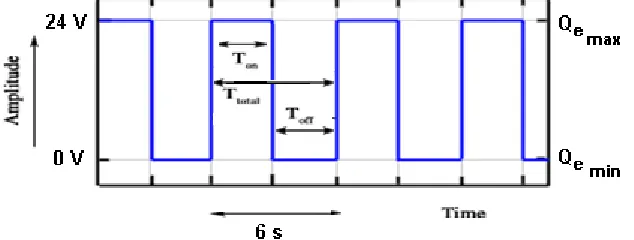
Literature Search. Characteristics, temperature and enthalpy on R507 refrigerant can be seen from the table showing the value of fluid and the density of the fluid type in the liquid and gas form (Franklin, Powell, Naeni, 1994). Danfoss (2001) designs an electrically operated expansion valve for a cooling system where the valve capacity is adjusted by modulating a pulse width of 6 seconds. If maximum cooling is required, the valve will remain open for almost 6 seconds from that period. Conversely, if a minimum cooling amount is required, the valve will remain open for almost 1 second of the period. The amount of cooling required is determined by the controller. If no cooling is required, the valve remains closed and functions as a solenoid valve. Alexander Lifson and Michael F Taras (2010) the patent application publication finds a pulsed suction valve for a refrigerant flow rate system in the exposure settings on the pulse width modulation control thus reducing the capacity of the flowing refrigerant system. X.F Wang, K. Tang, P.S Hrnjak, 2014 in thelast research is a pulsed press fall experiment system that can affect evaporator performance. This study considers the increase in heat transfer rate
performance in the evaporator occurring as a result of the pulsed pressure drop method. Pilot Valve Control of ICS servo type by Danfoss A/S, 2004 describes ICS scheme and its design. The design includes a wide open or on/off pressure, temperature and electric combination and a crankcase following installation of ICS on low pressure and high pressure side for refrigeration optimization. To regulate the ICS design combination required thermodynamic analysis..
Thermodynamic analysis. William Bolton, 2006 in the
thermal system has two basic blocks forming the system, ie resistance and capacitance where thermal resistance R is the resistance to the heat flow rate Q and defined as . is the hot temperature difference flow . For heat transfer between two points in convection mode, Newton's cooling law states that ( ). Where the heat flow rate (Q) produced is directly proportional to the heat transfer coefficient (U), surface area (A) and the temperature difference (∆T) that occurs. The thermal resistance for this heat transfer mode is thus equal to 1/UA. Thermal capacitance is a measure of time for the internal energy stored in the system. If the heat flow rate into the system is Q1 and the outflow rate is Q2, then the rate of change of system internal rate is . Increase in internal rate can cause temperature changes. Where M ais a mass and Cp is heat specific capacity. Therefore this equation can be written
.
heat power associated with the temperature, and the volume of the material. The laws of thermodynamics were first introduced by James Prescott Joule. The first legal sound of thermodynamics is: The increase of the internal energy that occurs from a thermodynamic system is proportional to the difference between the amount of heat energy added and the
work done by the system to its environment.. Larsen, 2005 mention that by understanding the processes that take place in a refrigeration system experienced by the refrigerant that circulates within the system, the arrangement of the whole process can be expressed in the form of a basic cycle that
drives the refrigeration system.
Control structure of refrigeration unit (Larsen, 2005)
Lienhard IV, 2001 states that the compressor unit changes the refrigrant volume in the refrigeration cycle is affected by the temperature changes in the evaporator unit and in the condenser unit outside the system. The cooling capacity can be determined by regulating the energy balance of the evaporator.
Research Gap. Selection of instruments and data or parameters observed and researched is to determine the optimization of refrigeration system, such as compressor parameters (High Pressure and Low Pressure), the compressor power that occurs at that time, the type of refrigerant (R507)
to determine the enthalpy to the pressure that produces the refrigerant volume rate through the expansion valve AKV PWM, with pressure limits set by the pressure process control valve (Pilot Control Servo-ICS) to keep the volume stability of refrigerant volume. A simple airflow scheme that circulates on a ship as shown in the figure where the outside air flow is open ( ) arranged in such a way that tangent to the
flow of load air temperature ( ) so the achievement of
room temperature in the vessel is highly dependent on wall temperature ( ) resulted.
Air Cooling Flow Scheme
Wall temperature ( ) certainly related to the number of heat transfer rates that occur in the evaporator component. Variable
AKV and ICS scheme control
The identification of the control elements in this scheme that plays a role is AKV and ICS. Valve capacity AKV control with pulse-width modulation. The signal will be transmitted in one period for 6 seconds and removed from the valve coil. This makes the valve open and close for refrigerant volume purposes. The relation between opening and closing times indicates an actual capacity. If there is an indispensable refrigerant requirement, then the valve will open almost all for 6 seconds in one period. In other words, the valve keeps opening in a small period. The amount of refrigerant required
is determined by the controller. When no refrigerant is supplied, the valve closes again. All of that is controlled by the input setting in EKC.
ICS valve are pilot valves operated for regulating of pressure, temperature, and function ON/OFF used on the refrigeration system. ICS valve designed for high and low pressure refrigerant. On air conditioning units on ICS scheme ships are as follows.
A Scheme of ICS with EVM, CVP and CVC in AC unit on vessel
On scheme of danfoss A/S, 2004, ICS no pilot schemes like this where ICS includes EVM, CVP (LP) and CVC. As it known EVM is regulates ON/OFF, CVP (LP) is constant regulation pressure LP and CVC is crankcase pressure regulation. From the scheme can be seen that the working method ICS is crankcase pressure regulation with regulation of shut off combined with constant pressure regulation LP. For setting ICS this is needed thermodynamic analysis of refrigeration cycle.
Research Aims. Initially the air-conditioning units on the vessel never reached the desired temperature where the system worked at the lowest stability so that the temperature of the
Figure Relationship of PWM with Heat Transfer Rate of Evaporator as Width of Amplitude
Materials And Methods.. Variable input data ie; Characteristics of Refrigerant 507, Electric current flowing in the compressor driving motor ( ), condenser temperature ( ) and evaporator temperature ( ). Based on then the power of the
compressor is determined ( ̇ ) through formulas ̇ √ . Condenser temperature ( ) and evaporator temperature ( ) can describe Mollier diagram of a refrigeration cycle that occurs so that the mass rate of refrigerant ( ̇)
determined by formula ̇ ̇
( ) and the refrigrant volume rate through the formula ̇
̇
( ).
Consequently, the rate of heat transfer released can be determined ( ̇ ) di kondensor then the rate of heat transfer in the evaporator ( ̇ ) through formulas ̇ ̇( ) and ̇ ̇ ̇. While the heat transfer rate in the evaporator ( ̇ )
determines the value of the wall Temperature ( ) which is generated by using a formula ̇
,where ( ) ( )
( )
( )
or can be seen in the graph below.
Approach and benefits. In this study focused on servo valve observation ICS and AKV scheme Pulse Width Modulation (PWM), thermodynamic analysis of the refrigeration cycle, conducting experiments by regulating the pressure valve servo valve CVP (LP) to optimize the system with the room
Result. The results of the observations and experiments conducted for the purpose of system optimization is achieved by showing three categories, among others :
1. Lowest stability category. where shows 12 A on
the driving motor with the refrigerant volume rate
23.64-25.86 ⁄ . The lowest stability observed indicates room temperature of di
with COP range . this data gather by direct observation.
Tabel of Lowes stability category
( ) ( ) ( ) ̇
̇
( ⁄ ) ( ) ̇ ( ) COP ( )
-9,00 40,80 4,13 23,64 16,99 21,12 3.76 18.80
-13,00 40,00 4,13 25,86 16,13 20,26 3.43 19.70
2. Unstable category. where move unstable up and down start from 16 A upto 21 A continuously it is called unstable conditio. The experimental results data on the servo pilot valve ICS on opening valve CVP (LP). COP the highest that can be seen in the table and graphic images on the compressor monitor .
Tabel of unstable category
( ) ( ) ( ) ̇
̇
( ⁄ ) ( ) ̇ ( ) COP ( )
-2,00 44,00 7,23 41,58 26,32 33,55 4.18 15,50
-6,30 43,50 7,06 36,69 28,72 35,77 3.73 14,40
-12,00 43,00 6,71 39,22 24,93 31,64 3.23 16,20
-15,00 42,50 6,37 39,82 22,76 29,12 3.02 17,20
-18,00 42,00 6,19 41,38 21,38 27,58 2.83 17,90
-21,00 41,80 5,85 41,31 19,45 25,30 2.63 18,80
-25,00 41,50 5,51 41,04 17,55 23,06 2.39 19,70
Figure of image monitor compressor unstable categories
3. From the above observations and experiments it is made the highest stability with the adjustment of the valve servo valve at the opening CVP (LP) by looking at the intermediate pressure parameters 4-6 kg/cm2 so that at the highest stability where
shows 25 A on the driving motor with the refrigerant volume rate 40.50-43.40 ⁄ . The highest stability indicates
room temperature of di with COP range . The experimental data can be
seen on the table and monitor the compressor and the image indicator .
Tabel Kategori Kestabilan Tertinggi
( ) ( ) ( ) ̇
̇
( ⁄ ) ( ) ̇ ( ) COP ( )
-2,00 45,00 8,60 40,50 36,86 45,46 4.04 10,57
Figure of graph Monitor compressor highest stability
CONCLUSION
(1) Experiments maximizing the falling process on a pulse width modulation scheme in AKV with the adjustment of the ICS pilot servo valve in this study should consider the amount of pressure CVP (LP) ie suction to the compressor, if too high passes 6 kg/cm2 or too low below 4 kg/cm2 then it is not achieved in temperature through thermodynamic analysis of the evaporator heat transfer rate which consequently the desired room temperature will never be reached.
Figure of wall temperature indicator ( )
(2) With the highest stability of the experimental results, the PWM duty cycle is obtained ½ where in the period of 6 seconds on the AKV is 3 seconds on 3 seconds off or 50% so the width of the area what happened was from upto where the pressure parameters move so far 0.82 kg/cm2 ON/OFF.
(3) Added a duty cycle 67% but because the rate of refrigerant
volume that occurs is 40.50-43.40 ⁄ the result of thermodynamic calculation analysis where maximum
displacement of Compressor Bitzer 4N.2Y is 67,7 ⁄ which means the effectiveness of the compressor has exceeded 60% so that the matter is undertaken with consideration of working hours and maintenance.
ACKNOWLEDGEMENTS
The authors are grateful to the SMART-Fish Indonesia, Jakarta Fisheries Univercity, University of Tasmania and Austaralia Mariteme College
REFERENCES
[1] W. Hong, E. Granryd, H. Kraft ; A PWM Control System for Regulating Refrigerant Flow Into an Evaporator, 1992.
[2] Xiaofei Wang; Ke Tang; Predrag S. Hmjak ; Effect of WM on
Perfomance of an Evaporator, 2014
[3] Lifson, Alexander (Manlius, NY, US) Taras, Michael F. (Fayetteville, NY, US) Refrigerant System With Pulse Width Modulation Control In Combination With Expansion Tool Control, 2008.
[4] Suction Modulation Valve For Refrigerant System With Adjustable Opening For Pulse Width Modulation Control, 2010
[5] Stoecker, W.F. Refrigeration and Air Conditioning. McGraw-Hill. 1998.
[6] ASHRAE Handbook, 1981 Fundamentals, American Society of Heating, Refrigeration and Air-Conditioning, Engineers, Atlanta, Ga 30329.
[7] Danfoss, A/S. Refrigeration and Air Conditioning Controls. Technical Brochure. Electrically Operate Expansion Valves Type AKV 10, AKV 15 and AKV20 Valves. Refrigeration Control Systems. ADAP KOOL. October 2001.
[8] Danfoss A/S. Refrigeration and Air Conditioning Control. Manual.
Controller for control of Industrial Evaporator EKC 135A.
ADAP-KOOL. 2002.
[9] Danfoss A/S. Refrigeration and Air Conditioning Division. Automatic Controll for Industrial Refrigeration Systems. Application Handbook. Danfoss A/S, http://www.danfoss.com. RA Marketing/MWA. 2006.
[10] John H. Lienhard IV/John H. Lienhard V. A Heat Transfer Textbook, Third Edition. June, 2001.
[11] Larsen, Lars Finn Sloth. Model Based Control of Refrigeration Systems, Ph. D. Thesis. NordBorg, Denmark. November, 2005. [12] Mihir Shen,. Principle of Thermal Control. University of Notre
Dame. USA, January 2004.
[13] Miller, Rex, Mark R. Miller. Air Conditioning and Refrigeration. Mc. Graw-Hill, 2006.
[14] Wang, Shan K. Handbook of Air Conditioning and Refrigeration. Mc Graw-Hill. 2001.