Prediction and Optimization of Tool Wear On A22E
(Bimetal Bearing Material) Using RSM and Genetic
Algorithm
1R.Babu,
2Dr. D. S. Robinson Smart,
3Dr. G.Mahesh,
4M. Shanmugam
1 Research Scholar, Department of Mechanical Engineering, Karunya School of Mechanical sciences, Karunya University, Coimbatore, Tamil Nadu, India.
2. Professor,Department of Mechanical Engineering, Karunya School of Mechanical sciences, Karunya University, Coimbatore, Tamil Nadu, India.
3 Professor,Department of Mechanical Engineering, Sree Sakthi Engineering College, Coimbatore, Tamil Nadu, India.
4Deputy General Manager (Operations), Bimetal Bearings Limited, Coimbatore, Tamil Nadu, India. 1[email protected], 2[email protected], 3[email protected]
Abstract-- Tool wear is an important criterion in hard finish
facing operation, which increases the temperature on the work piece, vibration, cutting force and decreases the surface roughness. In this present study, spindle speed, feed rate, depth of cut and end relief angle are taken as an input parameters. Experiment is conducted on A22E Bimetal bearing material using M42 HSS tool material in finish hard facing and tool wear was measured using tool maker’s microscope. Design of Experiments (DoE) methodology is used to conduct the experiment. Response Surface Methodology is used to predict the tool wear. The second order mathematical model in terms of machining parameters was developed. The direct and interaction effect of the machining parameters with tool wear were analyzed, which helped to select process parameter in order to reduce tool wear which ensures quality of the facing operation.
Index Term--
Spindle speed, Feed rate, Depth of cut, End Relief
angle, Tool wear, Response Surface Methodology (RSM), Genetic Algorithm (GA).
1. INTRODUCTION
In the recent scenario, due to the competitive marketing strategy the major goal of the manufacturing industry is to increase productivity and product quality with lesser production time. The quality of a product is strongly associated with the condition of the cutting tool. Mainly cutting tool plays a major role in manufacturing due to wear and breakage, so tool wear is found to have a direct impact on the quality of the product such as surface finish, dimensional accuracy and cost of the finished product is increased due to tool failure. The tool failure and the detection of tool failures are essential to improve manufacturing quality and to increase the productivity. The author [1] defined an empirical relationship between tool life and cutting speed (VTn = C) and C are coefficients.
Cutting tool life is one of the most important economic considerations in metal cutting. In roughing operations, the tool material, the various tool angles, cutting speed, and feed
rates are usually chosen to give an economical tool life. Clearly, any tool or work material improvement that increases tool life without causing unacceptable drops in production will be beneficial. To form a basis for such improvements, efforts have been made to understand the behavior of the tool, how it physically wears, the wear mechanisms, and forms of tool failure. Cutting parameters, work piece material, cutting tool geometry have a crucial influence on the accomplishment of desired product quality, tool wear, surface roughness, cutting force and temperature rise in tool and work piece etc. During turning and facing operation, friction between cutting tool and work piece materials plays a key role in temperature rise, wear etc. Among the above, tool wear has been found to be a most influencing factor. CNC machining centers play a major role in machining industry, even though spindle speed, feed rate, depth of cut were already programmed before machining but the machining performance and product quality are not guaranteed up to standard level. Therefore, the optimum turning and facing operation have to be accomplished.
parameters using CBN cutting tools in finish hard turning operation of hardened 52100 bearing steel. The authors suggest that the adhesion is the dominant wear mechanism within the range of cutting conditions. The performance of PCBN tool in the finish turning of GCr15 bearing steel was investigated to determine the influence of the work piece hardness on changes in cutting temperature and tool wear characteristics [6]. An experimental investigation has been done to clarify the effects of tool nose radius and tool wear on residual stress distribution of hard turning of bearing steel (JIS SUJ2) by using CBN tools with different nose radius, results the tool nose radius affects the residual stress distribution significantly[7]. The authors [8] conducted a simulation analysis of high speed hard turning of AISI 52100 bearing steel to study the cutting parameters of speed, feed, cutter geometry and work piece hardness results cutting force and feed force increase with increasing feed, tool edge radius, negative rake angle and work piece hardness. The authors [9] conducted an experiment to study the hard turning by using CBN tool of AISI 52100 bearing steel. The main objectives focus on tool wear and forces. The relationship between cutting parameters are analyzed using RSM by considering cutting speed, feed rate and depth of cut and machining output variables such as surface roughness, cutting forces were analyzed and modeled. The depth of cut plays a major role that influence cutting forces as compared to the feed rate and cutting speed. The authors [10] suggested that the cutting speed is the most influencing factor which effects tool life of turning of hardened 100Cr6 and PCBN cutting tools. The experiment was conducted using CBN insert of finish turning of hardened 52100 bearing steel. The objective of this study is to present a analytical methodology to find the CBN tool flank wear rate [11]. An orthogonal hard turning tests were conducted to study the effects of flank tool wear and cutting parameters (cutting speed and feed rate), on white and dark layer formation in hardened AISI 52100 bearing steel, using PCBN inserts [12]. An extensive study has been performed to investigate the tool-wear mechanisms of CBN cutting tools in finish turning of the X155CrMoV12 (AISI D2) cold work steel, X38CrMoV5 (AISI H11) hot work steel, 35NiCrMo16 hot work steel and 100Cr6 bearing steel (AISI 52100). A large variation in tool-wear rate has been observed in machining of these steels [13]. The main objective of the present study is to investigate the effects of process parameters (cutting speed, feed rate and depth of cut) on performance characteristics (tool life, surface roughness and cutting forces) in finish hard turning of AISI 52100 bearing steel with CBN tool. The optimization was carried out using ANOVA and RSM. The results show that feed rate and cutting speed strongly influence the surface roughness and tool life [14]. The authors [15] concluded that the cutting force was 50% larger and feed and thrust forces were 100% larger when turning AISI 52100 ball bearing steel of hardness 63 HRC as compared to turning the same material having hardness 32 HRC. The authors [16] conducted an experiment to model the relationship between tool wear and cutting parameters in turning processes. An experiment was conducted to clarify the effects of tool nose
radius and tool wear on residual stress distribution in hard turning of bearing steel JIS SUJ2. The results obtained in this study shows that the tool nose radius affects the residual stress distribution significantly [17]. The authors [18] conducted an experiment to find the CBN tool wear in hard turning, results adhesion is the dominant wear mechanism in turning hardened 52100 bearing steel with a hardness of 62 HRC using a low CBN content tool. An experimental study was carried out by using CBN tool during the turning of AISI 52100 bearing steel. The flank wear rate is low when turning at low cutting speed; the flank wear rate becomes quite large and sensitive to the feed rate [19]. The model was proposed and conducted an experiment in turning hardened 52100 bearing steel using the KD050 low CBN content insert. The CBN tool crater wear rate is formulated and validated over a wide range of cutting conditions [20]. The authors [21] presented a predictive model based on the artificial neural network (ANN). An experiment was conducted on hard machining of 52100 bearing steel, and the numerical results shows that more compressive residual stress in both axial and circumferential direction of the machined surface were obtained if higher values of the feed rate were chosen. The authors [22] proposed a model and validated through experimentally in finish turning of hardened 52100 bearing steel using a low CBN content tool, results suggest that adhesion is the dominant wear mechanism within the range of conditions that were investigated. An experimental investigation was carried out by using PCBN inserts.58 to machine finish hard turning of AISI 52100 bearing steel and suggested that the chamfer angle has a great influence on the cutting forces and tool stresses. All cutting force components increase with an increase of the chamfer angle [23]. An experimental investigation has been conducted to clarify the effects of tool nose radius and tool wear on residual stress distribution in hard turning of bearing steel JIS SUJ2 and suggested that the tool wear increases, the residual stress machined surface increases [24].
Various researchers have developed the surface roughness predictive models for the conventional hard turning of bearing materials. From the literature sources, it is found that the machining of A22E (BIMETAL BEARING MATERIAL) metal matrix composite is an important area of research, there is a limited research available in hard turning and facing operation of bearing materials on surface roughness.
BIMETAL Bearings are primarily used in engines of automobiles. The bearings are meant to reduce the friction between the moving parts of the engine crankshaft or crank shaft. The construction of Bimetal metal bearing consists of three layer structure consisting of strong steel backing. The back provides bearing rigidity and its press fit under severe conditions of increased temperature and cycling loads, a thin inter layer and lining of an aluminium alloy. Bimetal bearings are most often are produced as a combination of the following materials:
Steel with white metals
Steel with cast bronze
Steel with aluminium alloys
Fig. 1. Aluminium alloy bearing (BIMETAL Bearing)
In the present study, an attempt has been made to investigate the tool wear by considering the process parameters such as spindle speed, feed rate, depth of cut and end relief angle in hard facing operation using Response surface Methodology (RSM) approach. This methodology helps to obtain best possible cutting conditions and tool geometry in dry facing of A22E bearing material using M42 HSS tool material. The mathematical model is developed using Design Expert 6.0 package and also been tested by the analysis of variance test (ANOVA).
III. INFLUENCE OF END RELIEF ANGLE ON SINGLE
POINT CUTTING TOOL
The angle between front surface of the tool & line normal to base of the tool is known as End relief angle. End relief angle is used to minimize physical interference. If the relief angles are too large, the cutting edge will be weakened and in danger of breaking. If the cutting relief angle is too small, it causes the wear on the flank of the tool, thereby, significantly reducing the tool life. In general, for hard and tough material, the relief angle should be 6 to 8 degrees for HSS tools and 5 to 7 degrees for carbide tools. For medium steels, mild steels, cast iron, the relief angle should be 8 to 12 degrees for HSS tools and 5 to 10 degrees for carbide tools. For ductile materials such as copper, brass, bronze and aluminium, ferritic malleable iron, the relief angle should be 12 to 16 degrees for HSS tools and 5 to 14 degrees for carbide tools. The authors finally concluded that larger relief angle generally tend to produce a better surface finish [25].
Fig. 2. Single point cutting tool
IV. OPTIMIZATION BY USING GA
A Genetic Algorithm (GA) is a search technique used in computing to find true or approximate solutions to optimization and search problems. Genetic algorithms are categorized as global search heuristics. Genetic algorithms are a particular class of evolutionary algorithms that use techniques inspired by evolutionary biology such as inheritance, mutation, selection, and crossover. The evolution usually starts from a population of randomly generated individuals and happens in generations. In each generation, the fitness of every individual in the population is evaluated, multiple individuals are selected from the current population (based on their fitness), and modified (recombined and possibly mutated) to form a new population.
The most important components in a GA consist of:
Individual - Any possible solution
Population - Group of all individuals
Search Space-All possible solutions to the problem
Chromosome-Blueprint for an individual
Trait - Possible aspect (features) of an individual
Allele - Possible settings of trait (black, blond, etc.)
Locus - The position of a gene on the chromosome
Genome - Collection of all chromosomes for an individual
Table I
PROCESS FACTORS AND THEIR LEVELS
Table II
EXPERIMENTAL DESIGN MATRIX AND RESPONSE FACTORS
Run Spindle Speed
(A) rpm
Feed Rate (B) mm/rev
Depth of Cut (C) mm
End Relief Angle (D) degree
Tool Wear(T)
(Observed Value)mm
1 500 0.06 1.6 14 0.131
2 500 0.06 1.2 10 0.156
3 600 0.12 1.4 12 0.254
4 500 0.1 1.2 10 0.103
5 700 0.06 1.2 14 0.142
6 600 0.08 1.4 12 0.032
7 700 0.1 1.2 14 0.122
8 600 0.08 1.4 16 0.145
9 600 0.08 1.4 12 0.058
10 500 0.06 1.6 10 0.126
11 700 0.1 1.2 10 0.163
12 600 0.08 1.4 8 0.068
13 700 0.06 1.6 14 0.112
14 700 0.1 1.6 14 0.147
15 500 0.1 1.6 10 0.139
16 600 0.08 1.4 12 0.058
17 500 0.1 1.2 14 0.138
18 400 0.08 1.4 12 0.147
19 700 0.06 1.6 10 0.036
20 500 0.1 1.6 14 0.211
21 700 0.1 1.6 10 0.105
22 600 0.08 1.4 12 0.029
23 600 0.08 1.8 12 0.057
24 600 0.06 1.4 12 0.084
25 700 0.06 1.2 10 0.038
26 800 0.06 1.4 12 0.104
27 600 0.08 1.4 12 0.142
28 600 0.04 1.4 12 0.128
29 500 0.06 1.2 14 0.248
30 600 0.08 1 12 0.157
With this analytical model, an objective function with constraint can be created, and computation time can be saved. The RSM seeks for the relationship between design variable
and response through statistical fitting method. The response, tool wear (T) can be expressed as function of process
Variables Unit Coded Variable Level
Lowest Low Centre High Highest
-2 -1 0 +1 +2
Spindle Speed rpm 400 500 600 700 800
Feed Rate mm/rev 0.04 0.06 0.08 0.1 0.12
Depth of Cut mm 1 1.2 1.4 1.6 1.8
parameters. The end relief angle (D), spindle speed (A), feed rate (B) and depth of cut (C) as shown in Eq. (1)
Tool wear (T) = ψ(Diu, Aiu, Biu, Ciu) + eu---(1)
where,
ψ - response surface, eu - residual,
u - no of observations in the factorial experiment
iu - represents level of the ith factor in the uth observation.
When the mathematical form of ψ is unknown, this function can be approximated satisfactorily within the experimental region by polynomials in terms of process parameter variable. The selected design matrix, is a three-level, four factor central composite rotatable factorial design (CCD) consisting of 30 sets of coded conditions. The ranges of all the parameters were fixed by conducting trial runs. This was performed by varying one of the parameters while retaining the rest of them as constant values. The upper limit of a given parameter was coded as (+2) and the lower limit was coded as (–2).The intermediate levels of -1, 0, +1 of all the variables have been calculated by interpolation. Thus, all the 30 experimental runs to allow the estimation of the linear, quadratic and two way interactive effects of the process parameters.
Xi = 2(2X − (Xmax + Xmin)) --- (2) (Xmax − Xmin)
Where,
Xi - The required coded value of a variable X X - Is any value of the variable from Xmin to Xmax.
Xmin - Is the lower limit of the variable Xmax - Is the upper limit of the variable The intermediate values coded as −1, 0, and 1.
VI. EXPERIMENTAL SETUP
The test specimen Bimetal Bearing of size 95 mm diameter and thickness 2 mm are selected for experimental purpose. The outer side of bimetal bearing consists of steel and inner side is made up of aluminum. Bimetal bearing is softest and it consists of 6 - 20% tin, 1% copper, 2- 4% silicon and highly strengthened by nickel and other elements. These type of bearings used in the passenger cars with low and medium load gasoline engines. The experiments were conducted on special type of CNC lathe with M42 HSS single point facing tool under dry condition. The machining operations were carried out as per the conditions provided by the design matrix. The tool wear was measured using tool maker’s microscope on the flank surface of the single point turning tool specimen. The machining of Bimetal Bearing experimental set-up is shown in Fig.2.
Table III
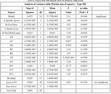
ANOVA TABLE FOR THE PREDICTION OF SPINDLE VIBRATION
Analysis of variance table [Partial sum of squares - Type III]
Sum of Mean F p-value
Source Squares df Square Value Prob > F
Model 0.072 14 5.173E-003 3.11 0.0184 significant
A-Spindle Speed 9.322E-003 1 9.322E-003 5.60 0.0318
B-Feed Rate 6.370E-003 1 6.370E-003 3.83 0.0693
C-Depth of cut 3.825E-003 1 3.825E-003 2.30 0.1502
D-End Relief angle 0.012 1 0.012 7.28 0.0165
AB 4.865E-003 1 4.865E-003 2.92 0.1079
AC 4.556E-005 1 4.556E-005 0.027 0.8708
AD 3.306E-005 1 3.306E-005 0.020 0.8898
BC 4.064E-003 1 4.064E-003 2.44 0.1389
BD 1.785E-003 1 1.785E-003 1.07 0.3167
CD 1.563E-006 1 1.563E-006 9.391E-004 0.9760
A^2 5.808E-003 1 5.808E-003 3.49 0.0814
B^2 0.026 1 0.026 15.77 0.0012
C^2 2.703E-003 1 2.703E-003 1.62 0.2218
D^2 2.635E-003 1 2.635E-003 1.58 0.2274
Residual 0.025 15 1.664E-003
Lack of Fit 0.016 10 1.621E-003 0.93 0.5724 not significant
Pure Error 8.745E-003 5 1.749E-003
Cor Total 0.097 29
VII.DEVELOPMENT OF MATHEMATICAL MODEL
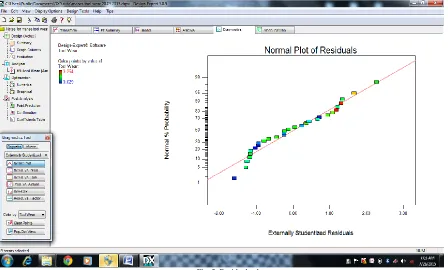
The analysis is carried out with the experimental data using Design Expert V 9.0.4 software of state ease. The model is checked for its adequacy using ANOVA (analysis of variance). Table VIII shows ANOVA table for the prediction of tool wear (T). It is observed from the Table VIII that the model is significant and the lack of fit is not significant which infers the significance of the model. Values of Prob> F less than 0.05 indicate the model terms as in significant and the values greater than 0.10 indicate the model terms as not significant. The Model F-value of 3.11 implies that the model is significant. There is only a 0.25% chance that an value this large could occur due to noise. The "Lack of Fit F-value" of 0.93 implies the Lack of Fit is not significant relative to the pure error. There is a 12.05% chance that a "Lack of Fit F-value" this large could occur due to noise. Non-significant lack of fit is good. The Fig.5 shows the Predicted Vs Actual model. The regression equation obtains from the Design Expert software in terms of actual factors are given:
Tool Wear (T) = +2.43364 2.43646E003* A 19.19687* B -1.03552* C -0.023240* D +8.71875E-003 * A * B 8.43750E005 * A * C 7.18750E006 * A * D +3.98438 * B * C -0.26406 * B * D +7.81250E-004 * C * D +1.45521E-006 * A2 +77.31771 * B2 +0.24818 * C2+2.45052E-003 * D2.
Where,
A = Spindle speed in rpm B = Feed rate in mm/rev C = Depth of cut in mm D = End Relief angle in degree
VIII. RESULTS AND DISCUSSION
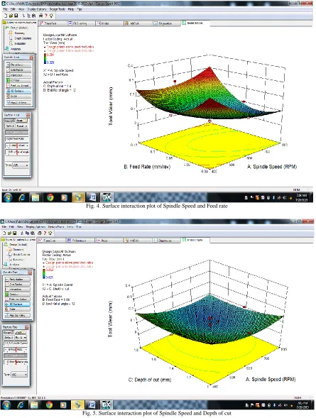
The interaction effect of these process parameters on tool wear were discussed below. Fig. 4 shows the interaction effect of feed rate and spindle speed on tool wear. As the increase in spindle speed from 600 rpm to 800 rpm the tool wear value is
low, whereas the feed rate has the inverse relationship on the tool wear. Therefore, higher
spindle speed and feed rate between 0.06mm to 1mm has to be chosen as low tool wear. Fig.5 shows the interaction effect of spindle speed and depth of cut on tool wear. It is evidenced
from the figure that at lower spindle speed and higher depth of cut has a significant influence. The tool wear increases when the spindle speed is higher and low depth of cut. Fig. 6 shows the interaction effect of spindle speed and relief angle on tool wear. From the Figure
Fig. 4. Surface interaction plot of Spindle Speed and Feed rate
Fig. 6. Surface interaction plot of Spindle Speed and End Relief Angle
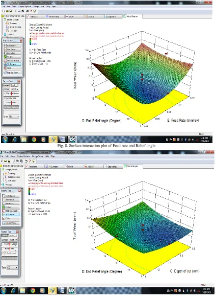
Fig. 8. Surface interaction plot of Feed rate and Relief angle
Fig. 9. Surface interaction plot of depth of cut and relief angle is noted that the both spindle speed and relief angle are
influencing the tool. The tool wear is significantly higher between 12° to 16° and also the similar result is observed between 400 rpm to 500 rpm. From the result, the industry preferring to fix the relief angle between 8° to 10°. Fig. 7 shows the interaction effect of feed rate and depth of cut on
and depth of cut between 1.4 mm to 1.6 mm will produce lower tool wear as shown in Fig.9.
VIII. EVALUATION OF GA RESULTS
In this present study, the optimization wear was carried out to minimize the cutting parameter based on Genetic Algorithm methodology.The minimization of tool wear by using GA can be expressed by the equation
Minimize: T (A, B, C, D)
Within ranges of cutting parameters,
400 rpm ≤ A ≤ 800 rpm
0.04 mm/rev ≤ B ≤ 0.12 mm/rev
1 mm ≤ C ≤ 1.8 mm
8 ° ≤ D ≤ 16°
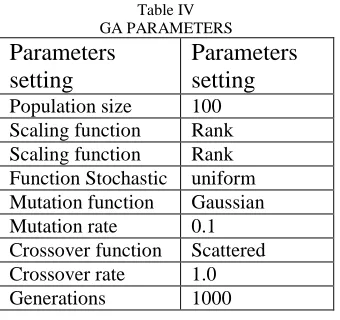
The number of the initial population size, the type of selection function, the crossover rate, mutation rate and the generations to be considered to get the best optimal results. The Table 4 shows the GA operators. By solving the optimization problem using MAT LAB 7.0, GA predicts the optimum tool wear as 0.0180 mm for the machining of Bimetal bearing in the selected cutting condition range. The GA-predicted tool wear value (best fitness function) is expected to be lower than the minimum tool wear value of the experimental and regression models.
Table IV GA PARAMETERS
Parameters
setting
Parameters
setting
Population size 100 Scaling function Rank Scaling function Rank Function Stochastic uniform Mutation function Gaussian
Mutation rate 0.1
Crossover function Scattered Crossover rate 1.0
Generations 1000
IX. VALIDATION OF THE MODEL
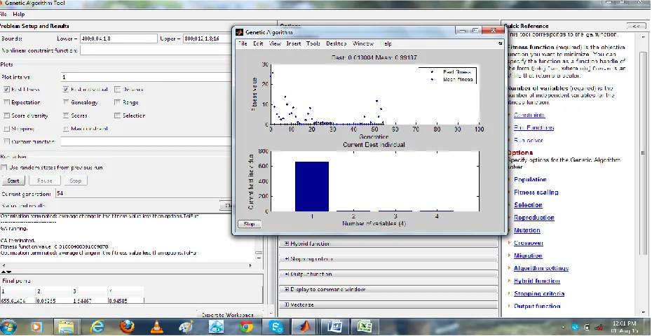
Table II shows that a regression model developed using CCD by the RSM of DoE. Fig.10 shows the comparison of predicted vs experimental value of Tool wear from RSM of DoE. Table 5 shows the comparison of predicted vs experimental value of Tool wear. The GA-predicted optimum conditions were further validated with physical measurements. The percentage of error is found to be within ±2 % which shows the validity of the model. The experimental results of tool wear with the optimum cutting parameters (as predicted by GA) shows the good agreement. Figure 10 shows the performance of fitness value with generation and the best individual performances of variables in coded form.
Fig. 10. shows the performance of fitness value with generation and the best individual performances of variables in coded form.
Table V
OPTIMIZED PROCESS PARAMETER PREDICTED BY GA
X. CONCLUSION
From the regression model developed using Central Composite Design (CCD) by the Response Surface Methodology (RSM) of Design of Experiments (DoE), the experimental investigation has been done for facing operation considering, the factors such as Spindle Speed, Feed Rate, Depth of cut, and End relief angle to predict tool wear of Bimetal Bearing, the following conclusions are drawn:
The Spindle Speed and Feed rate are the most important parameters to be considered for tool wear compared to the other factors such as depth of cut and end relief angle. The better tool life was obtained at the end relief angle (8°-10°) and spindle speed (600 rpm to 800 rpm). The tool wear is minimum value at the region of feed rate (0.06mm - 0.1 mm).The tool wear is minimum at the region of depth of cut (1.4 mm – 1.6 mm). Further GA predicts the optimum tool wear as 0.0180 mm for the machining of Bimetal bearing in the selected cutting condition range. The confirmatory result shows good arguments for experimental vs predicted value.
REFERENCE
[1] Taylor, F. W, On the Art of Cutting Metals, The American Society
of Mechanical Engineers, (1906) New York, USA
[2] Devendiran. SK, Manivannan. S, Rajeswari, C, Joshua Michael
Amarnath and Apoorv Prasad, Bearing fault diagnosis using CWT, BGA and Artificial Bee Colony Algorithm, International Journal of Mechanical & Mechatronics Engineering, 15 (03), 2015,1-16.
[3] Yong Huang and Steven Y.Liang, Modelling of CBN tool crater
wear in finish hard turning, The International Journal of Advanced Manufacturing Technology, 24, ( 9-10), 2004, 632-639.
[4] Yong Huang and Steven Y.Liang, Effect of Cutting Conditions on
Tool Performance in CBN Hard Turning, Journal of Manufacturing Process, 7(1), 2005, 10-16.
[5] Yong Huanga and Ty G. Dawson, Tool crater wear depth modeling
in CBN hard turning, Wear, 258(9), 2005, 1455–1461.
[6] Liu. X.L, Wen. D.H, Li. Z.J, Xiao. L. and Yan. F.G. Cutting
temperature and tool wear of hard turning hardened bearing steel, Journal of Materials Processing Technology, 129(1–3), 2002, 200– 206.
[7] Meng Liu, Jun-ichiro Takagi and Akira Tsukuda, Effect of tool
nose radius and tool wear on residual stress distribution in hard turning of bearing steel, Journal of Materials Processing Technology 150, 2004, 234–241.
[8] Qian. L , and M.R. Hossan, Effect on cutting force in turning
hardened tool steels with cubic boron nitride inserts, Journal of
Material Processing Technology, 191(1-3),2007,274-278.
Trial Spindle Speed
(A)
Feed rate (B)
Depth of cut (C)
End relief angle
(D)
Confirmatory test for Surface roughness
% error Predicted
GA model
Experimental Value
rpm mm/rev mm Degree µm µm
1 700 0.08 1.6 12 0.114 0.113 0.87
2 500 0.06 1.2 8 0.084 0.081 0.35
[9] Boucha. K, Athmane. M. Y, Mabrouki. T and Rigal. F. J. Statistical analysis of surface roughness and cutting forces using response surface methodology in hard turning of AISI 52100 bearing steel with CBN tool, Int. Journal of Refractory Metals & Hard Materials, 28, 2010, 349–361.
[10] Banga, G.C and Abrao, A.M. Turning of hardened 100Cr6 bearing
steel with ceramic and PCBN cutting tools. J. Mater. Process. Technol. 144, 2003.143–237–241.
[11] Yong Huang and Steven Y. Liang, Modeling of CBN Tool Flank
Wear Progression in Finish Hard Turning, Transactions of the ASME, 126, 2004, 98- 106
[12] Attanasio, C. Cappellini, G. Rotella, R. M’Saoubi and Umbrello.
D. Tool wear effects on white and dark layer formation in hard turning of AISI 52100 steel, Wear, 286–287, 2012, 98–107.
[13] Gérard Poulachon, Bandyopadhyay. B.P, Jawahir. I.S. Sébastien
Pheulpin and Emmanuel Seguin , Wear behavior of CBN tools while turning various hardened steels, Wear 256, 2004, 302–310.
[14] Samir Khamel1, Nouredine Ouelaa and Khaider Bouacha,
Analysis and prediction of tool wear, surface roughness and cutting forces in hard turning with CBN tool, Journal of Mechanical Science and Technology 26 (11), 2012, 3605-3616.
[15] Konig. W. Komanduri. R. Tonshoff. H. K. and Ackershott. G.
Machining of hard materials, Annals of the CIRP, 33 (2), 1984, 417-428.
[16] Liu. XL, Wen. DH, Li. ZJ, Xiao. L and Yan. FG. Cutting
temperature and tool wear of hard turning hardened bearing steel. Journal of Material Processing Technology, 129(1–3), 2002, 200– 206.
[17] Meng Liu, Jun-ichiro Takagi and Akira Tsukuda, Effect of tool
nose radius and tool wear on residual stress distribution in hard turning of bearing steel, Journal of Materials Processing Technology 150, 2004,234–241.
[18] El-Helieby. S.O.A and Rowe. G.W. A quantitative comparison
between residual stresses and fatigue properties of surface-ground bearing steel (EN31), Wear, 58, 1980, 155–172.
[19] Lin Z-C and Chen D-Y. A study of cutting with a CBN tool.
Journal of Materials Processing Technology 49, 1995, 149–164.
[20] Yong Huang and· Steven Y. Liang, Modelling of CBN tool crater
wear in finish hard turning, International Journal of Advanced Manufacturing Technology, 24, 2004,632–639.
[21] Umbrello. D, Ambrogioa. G, Filice, L.and Shivpuri, R. An ANN
approach for predicting subsurface residual stresses and the desired cutting conditions during hard turning. Journal of Materials Processing Technology, 189, 2007, 143–152.
[22] Yong Huang and Dawson. Ty G. Tool crater wear depth modeling
in CBN hard turning, Wear. 258, 2005, 1455–1461.
[23] Kurt, A. and Ulvi, S., “The effect of chamfer angle of
polycrystalline cubic boron nitride cutting tool on the cutting forces and the tool stresses in finishing hard turning of AISI 52100 steel,” Materials and Design, 26(4), 2005,351-356.
[24] Meng Liu, Jun-ichiro Takagi and Akira Tsukuda, Effect of tool
nose radius and tool wear on residual stress distribution in hard turning of bearing steel, Journal of Materials Processing Technology, 150 (3), 2004, 234–241.
[25] Edward G. Hoffman,, Christopher J., McCauley.,and Muhammed
Iqbal Hussain., Shop Reference for Students and Apprentices, New York : Industrial Press, 2nd ed. 2000.
[26] Logesh. K, Muralinath. P, Poyyamozhi. N, Dilip Raja.N and