Abstract— Stable platforms with different degrees of freedom (DOF) have numerous applications in industry and trade, such as in aerospace, astronomy and robotics. The advantage of these platforms is the sustainability of their behavior and performance under different environmental and work conditions. Different types of equipments like imaging systems are placed in them as a load to have stable behavior. Stable platforms with different DOF are either of the force or indicator stabilization types. The present study offers an overview of the structure and function of single axis force stabilizers and analyzes the dynamic and kinematic equations governing them. The behavior and performance of the target platform in open loop and closed loop conditions is simulated in MATLAB/SIMULINK using these equations and the characteristics of existing gyroscopic single axis force stabilizer. In open loop mode, the performance of the system under 11.5O/sec angular velocity of body is evaluated. In closed loop mode, system response is evaluated under the influence of an external sinusoidal wave with an amplitude of 0.3 Newton meters torque which is applied around the stability axis of the stable platform. The simulation result shows the consistency of the simulation results with the actual behavior of the platform under the same working conditions.
Index Term— Force stabilizer, gyroscope, indicator stabilizer, simulation.
I. INTRODUCTION
Sets and systems in industry and trade use stable platforms with different degrees of freedom (DOF) for imaging. These stable platforms have many applications in trade and industry such as automotive industries, aerospace industries, military industries, medical equipment industries and etc. These systems require imaging and a camera with a resolution that is not affected by vibration and consecutive jolting to identify, track and record the target. These platforms are usually placed in the nose of a guided device and can search the space within their field of view by observing the principle of sustainability. Like any other control system, the output of the platform axis angle is compared with reference input in the imaging system line of sight and a compensator issues the appropriate torque command in response to the generated error.
The present study examined a gyroscopic single axis force stabilizer in which an imaging system is placed. The final
M.S. Mirzajani Darestani, is with Young Researchers and Elite club, Parand Branch, Islamic Azad University, Parand, Iran. (e-mail:
performance criteria for the stabilizer system are the quality, sharpness and contrast of the image created by the optical sensor in the presence of carrier and target movement.
Reduced volatility is usually considered the measure of proper functioning of the stabilizer.
Recent advances have improved stabilizer performance. For example, increased operational bandwidth directly reduces turbulence. Advances in gyroscopes, actuators and electronic systems enable new controllers to operate with more bandwidth. Volatility and disordered and unwanted movement in a stabilizer decrease as the noise decreases in gyroscopes, actuators and electronic components.
Previous studies examining gyroscopic stabilizers have discussed identification of platform systems, stabilizer design, evaluation of the application of these platforms in different industries, and determination of test and evaluation methods. [1] is about designing controller for an electromechanical actuator with time delay. In this article the captured data, related to several test sets at different conditions for system identification, were used for model estimation and validation purposes. In [2], authors address three main topics; experimental identification, uncertainty modeling, and robust control design for a real EMA harmonic drive system. In this article, the linear model of the harmonic drive system is identified based on the test data. The captured data, related to several test sets at different conditions, were used for model estimation and validation purposes. In [3], a comparative study of adaptive vibration control approaches is presented for the system identification for micro-electro-mechanical systems (MEMS) z-axis gyroscope. In [4] and [5], the structure and operation of inertial stabilized platforms were studied. In these articles, the equations of motion related to these platforms were also fully discussed. Researchers in [6] specifically studied the direct and indirect stabilization of imaging system in two axis platforms and the performance of these two methods were also discussed and compared to each other. The present study modeled a sample gyroscopic single-axis force stabilizer and obtained the equations necessary to model and simulate the stabilizer. The structure of the gyroscopic single-axis force stabilizer was simulated using SIMULINK in MATLAB to allow evaluation of its behavior and performance
Simulation of Single-Axis Force Stabilizer
Behavior in Open Loop and Closed Loop
Conditions According to its Equations of
Motion
under various operating, environmental and functional conditions. The goal is to reduce the cost required to carry out practical and laboratory experiments for evaluation of the behavior of this stabilizer.
Next sections of this article are as follow: In section 2, an introduction of single-axis force stabilizer is presented. Section 3 was assigned to the dynamic modeling of table platform components. Section 4 discusses about the kinematic equations of stable platform. Section 5 was assigned to the dynamic equations of single-axis stabilization system. In section 6 evaluation of stability and design of controller for single axis force stabilizer is presented. In section 7, the simulation results are presented. Section 7 is the conclusion part of the article.
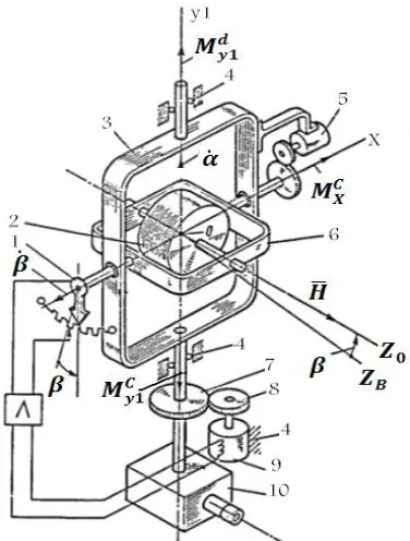
II. ACTIVE GYROSCOPIC SINGLE-AXIS FORCE STABILIZER Fig. 1 shows an active gyroscopic single-axis force stabilizer with a camera attached to its outer frame for the purpose of stabilization. The set of a gyroscope at 3 DOF and a camera form the stable platform. Outside intruder torques of which affect the axis prioritize ̇ for the inner frame and creates deviation. The torque reversal engine generates the main gyroscope axis to reduce and limits gyroscope priority by measuring the deviation angle using goniometer no. 1 to generate a feedback signal and send a command to torque maker engine no. 9 to maintain the angle at near zero.
Fig. 1. Active single axis force stabilizer for camera stabilization: (1) goniometer; (2) gyroscope rotor; (3) stable platform; (4) body; (5) controlled
torque maker (tracker); (6) rotor frame; (7) and (8) gear box; (9) stabilizer motor; (10) stabilized object (camera).
The gyroscopic torque has the task of neutralizing the intruder torque with a priority speed of ̇ at the first moment and immediately after becomes a non-zero value, controlling restorer torque is created by the feedback circuit
and helps the gyroscopic torque. The torque ends and all outside intruder torque is neutralized by the controlling torque [7]. The outer frame and the set of the camera become stable around the axis despite the rotation of the body and the camera remains constant in inertial space despite the movement of the body. This type of gyroscopic stabilizer is called an active force gyroscopic stabilizer.
III. DYNAMIC MODELING OF STABLE PLATFORM A. Gimbal Coordinate System
An orthogonal coordinate system takes the form of a tree diagram which includes all members of the stabilizer system as shown in Fig. 2. The ( ) coordinates are relative to the platform, ( ) are relative to the y gyro and ( ) coordinates are relative to the body.
Fig. 2. Tree diagram of gimbal coordinate system.
Coordinates of each components can be defined as a vector and transferring it from member to member by suitable linear transformation matrix. Transformation matrix from the stable platform to the body is defined as (1) where is the angle of body relative to the stable platform.
( 1 ) [
] B. Gyro Coordinate System
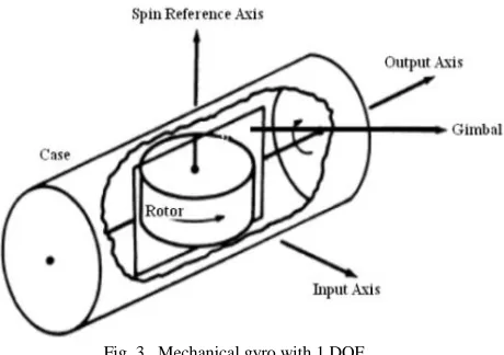
Fig. 3. Mechanical gyro with 1 DOF.
For obtaining transformation matrix from stable platform to y gyro ( ), platform should rotate around axis then should rotate around axis. Finally, the transformation matrix from stable platform to gyro y is as (2):
( 2 ) [
] [
]
[
]
IV. KINEMATIC EQUATIONS OF STABLE PLATFORM A. Kinematics of Stable Platform
The angular velocity vector of platform ⃗⃗⃗⃗⃗ equals the sum of the angular velocity vectors of the body [ ⃗⃗⃗⃗⃗ ] and relative angular velocity between the body and stable platform (angular velocity of stable platform relative to the body [ ⃗⃗⃗⃗⃗⃗⃗⃗⃗ ]) [8]:
⃗⃗⃗⃗⃗ ⌊ ⌋ ⃗⃗⃗⃗⃗ + ⃗⃗⃗⃗⃗⃗⃗⃗⃗ (3) The angular velocity of the stable platform in the coordinate system is expressed relative to inertia in the form of (2). Note that the body angle is defined relative to the stable platform as θ; thus, the angular velocity of stable platform relative to the body equals θ̇.
( 4 ) ⃗⃗ [
] [ ] [ ̇] [ ̇]
[ ]
The derivative of this vector in a stable platform coordinate is:
( 5 ) ⃗⃗ ̇ [ ̇ ̈] [
̇ ̇
̇ ]
B. Kinematic Equations of y Gyro
The angular velocity vector of the y gyro in the y gyro coordinate system is [9]:
( 6 )
⃗⃗⃗⃗⃗⃗ ⌊ ⌋ ⃗⃗⃗⃗ ⃗⃗⃗⃗⃗⃗⃗⃗⃗⃗
( 7 ) ⃗⃗ [
] [ ̇]
( 8 ) ⃗⃗ [
̇
] [ ]
The derivative of (8) in a stable platform coordinate is:
( 9 ) ⃗⃗ ̇ [
̇ ̇
̇ ̇ ̈
] [ ̇ ̇ ̇ ]
V. DYNAMIC EQUATIONS OF SINGLE-AXIS STABILIZATION SYSTEM
Any member of the system acts as a rigid body and torque equation is as (10):
( 10 ) ⃗⃗ =i ̇⃗⃗
⃗⃗⃗ net torque, which is inserted into each frame, includes the torque applied to that frame from the adjacent outer frame and the reaction torque from the adjacent inner frame to that frame. The relevant equations are expressed in the coordinate system of each member. The members and adjacent frame are defined as shown in Fig. 2. Dynamic equations for this type of stabilizer in form of force are written such that they start with the innermost member (the gyro) and continue to the outermost member (the body).
The symbol [*] on the torque component denotes the existence of that component on the dynamic joint axis [free] between two adjacent members. These dynamic axes are denoted as a dotted line in Fig. 2. The axes denoted a continuous line are those bound by members. The constraints denote the reaction torque in the hinge-bound axis. The free axis represents 1 DOF between the two neighboring members of the system [10].
A. Gyro Dynamic Equations
If the gyroscope body is considered to be a part of the body connected to the platform, then the moving part of the gyroscope (the floating section) requires dynamic equations for the inner frame and its accessories and the gyroscope rotor. In this case, the total angular momentum of the floating section can be shown in form of a vector in (11) [11]:
( 11 ) ⃗⃗ [ ] ⃗⃗ ⃗⃗
In which ⃗⃗ is the total angular momentum of the floating part of the gyroscope and ⃗⃗ is the angular momentum of the gyro rotor (gyro kinetic moment) and is:
( 12 ) ⃗⃗ [ ] [ ]
is the polar inertia of the rotor, is the angular velocity of the twister rotor and is considered to be constant. [ ] is the moment of the main inertia of the floating part as shown in (13):
( 13 ) [ ] [
Where the moments of inertia of the rotor axis are included in and , but does not include the polar moment of inertia of the rotor, and ⃗⃗ is the absolute angular velocity of the floating part [12]. Equation (14) can be deduced by considering the above definition and (11) as:
( 14 ) ⃗⃗ [ ] , ̇ [ ̇ ̇ ̇ ]
Using the Euler-Newton torque equation produces:
( 15 ) ∑ ̇ ̇ ⃗⃗ ⃗⃗
The vector multiplication terms of (15) can be calculated as:
( 16 ) ⃗⃗ ⃗⃗ [ ]
Substituting (14) and (16) into (15) produces:
( 17 ) ∑ [ ] [ ̇ ̇ ̇ ] [ ]
The term required for simulation of a gyro relates to the hinge axis as:
( 18 ) ̇
In which is obtained using (19) [13]. The frictional torque equals the negative coefficient of friction in gyro angular velocity compared to the stable platform as:
( 19 ) ̇
is the viscous damping coefficient for a floating gyro and is the control torque to direct the stable platform toward a particular direction.
B. Dynamic Equations of Stable Platform
The total angular momentum of the stable platform can be shown in form of a vector as:
( 20 ) ⃗⃗ [ ] ⃗⃗
Where ⃗⃗⃗⃗⃗ is the angular momentum of the stable platform and ⌊ ⌋ is the main inertia moment of the stable platform and can be expressed in the Newton-Euler equation as [14]:
( 21 ) ∑ ⃗⃗ ⃗⃗ ̇
In which ⃗⃗ ̇ is a derivative of the angular momentum vector of the stable platform compared to the inertia as:
( 22 ) ⃗⃗ ̇ ⃗⃗ ̇ ⃗⃗ ⃗⃗
The main inertia moment of stable platform is defined as:
( 23 ) [ ]
Substituting (4) and (23) into (22) produces:
( 24 ) ⃗⃗ [ ] [ ] [ ]
Using the derivative of (24) produces:
( 25 ) ⃗⃗ ̇ [ ̇ ]
The vector multiplication in right side of (24) can be calculated as (26):
( 26 ) ⃗⃗ ⃗⃗ | ⃗ | ⃗
According to (25), (26) and (24) produce:
( 27 ) ⃗⃗ ̇ [ ̇ ] [ ] [ ̇ ]
To calculate the torque exerted by the gyro on the platform, is the matrix of the converting gyro on the platform caused by the orthogonality of converting matrixes as:
( 28 ) [ ] [ ]
Torque exerted by gyro on the stable platform can be calculated as: ( 29 ) ⃗⃗ ⃗⃗ [ ]
Torque exerted by the body on the stable platform can be calculated as: ( 30 ) ⃗⃗ [ ]
In which is obtained using (31). Note that the frictional torque exerted on the platform by the body is equal to the negative viscous damping coefficient [ ] at an angle to the stable platform relative to the external frame [ ̇ ], which means: ( 31 ) ( ̇) ̇
Where is the control torque of the stabilizer motor that stabilizes the platform around the y axis [15]. The total external torque exerted on the stable platform can be calculated as: ( 32 ) ∑ ⃗⃗ ⃗⃗ ⃗⃗ [ ]
( 33 ) [ ] [ ̇ ]
Rewriting the second equation for simulation in (33) produces:
( 34 ) ̇
Rewriting (35) produces:
( 35 ) ̇
Two terms should be transferred to the left side of the equation [16]. This equation is then extended using (17) as:
( 36 ) ̇
The use of gyro kinematic (9) produces:
( 37 ) ̇ ̇ ̇ ( 38 ) ̇ ̇
In which is the sentence of ̇ that does not contain ̇ .
( 39 ) ̇
Substituting (38) and (39) into (37) produces:
( 40 ) ̇
In which does not contain ̇ :
( 41 )
Here, components containing ̇ are separated from other sentences. Equation (17) produces:
( 42 ) ̇
Gyro kinematic (5) produces:
( 43 ) ̇ ̇ ̇ ( 44 ) ̇ ̇
In which is a sentence of ̇ that does not contain ̇ . ( 45 ) ̇
Substituting (45) into (44) produces:
( 46 ) ̇
In which does not contain ̇ :
( 47 )
Substituting (40) and (46) into (36) produces:
( 48 ) ̇ ̇ ̇
Terms containing ̇ in (48) on the left side become [17]: ( 49 ) ̇
In which is:
( 50 )
And can be calculated using (41) and (47), respectively, and using (32). Rewriting (49) produces:
( 51 ) ̇
VI. EVALUATION OF STABILITY AND DESIGN OF CONTROLLER FOR SINGLE AXIS FORCE STABILIZER
Evaluation of the stability of the single axis force stabilizer assumes angular velocities for the body and their
rate of zero. Equation (4) can be rewritten using these assumptions as:
( 52 ) ⃗⃗ [ ̇]
It can be concluded from (8) using these assumptions that: ( 53 ) ⃗⃗ [ ̇ ̇ ̇ ]
Substituting (52) and (53) into (18) and (51) and performing linearization on resulting equations around the zero operating point (with angles and angular velocity of the platform being zero) produces:
( 54 ) θ̈ ̇θ̇ ̇ θθ̇ ( 55 ) ̈ θ̇ θ̇ ̇
By linearization of (54) and (55) around zero operating point (angles and angular velocities of platform is zero) [18]: ( 56 ) θ̈ ̇ θ θ̇ ( 57 ) ̈ θ̇ ̇
Assuming ̇, the system can be expressed as:
( 58 ) ̇
In which state variables are as (59):
( 59 ) θ θ̇ ̇
Coefficient matrix of state variables is as (60):
( 60 ) [ θ ]
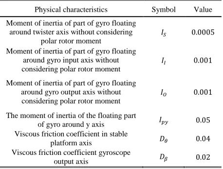
Table I shows the total physical characteristics of stable single axis force stabilizer.
TABLE I
PHYSICAL CHARACTERISTICS OF STABLE SINGLE AXIS FORCE STABILIZER
Physical characteristics Symbol Value
Moment of inertia of part of gyro floating around twister axis without considering
polar rotor moment
Moment of inertia of part of gyro floating around gyro input axis without considering polar rotor moment
Moment of inertia of part of gyro floating around gyro output axis without considering polar rotor moment
The moment of inertia of the floating part
of gyro around y axis Viscous friction coefficient in stable
platform axis
Viscous friction coefficient gyroscope
The stability of the system can be evaluated using the Routh-Hurwitz method. The characteristic equation is obtained by solving for the determinant of the matrix as:
( 61 )
Table II lists the Routh-Hurwitz array calculated for characteristic (61). The stability condition of Routh-Hurwitz requires no change of sign in the first column of the left side of Table 2. The following two conditions must always be met.
The stability condition of system can be rewritten as: ( 62 )
TABLE II
ROUTH-HURWITZ ARRAY FOR CHARACTERISTIC EQUATION
0
0
0
VII. SIMULATION
The simulation is done under open-loop and closed-loop conditions.
A. Open-loop system response
Assume that the control input is zero and evaluate the system response under external disturbances.
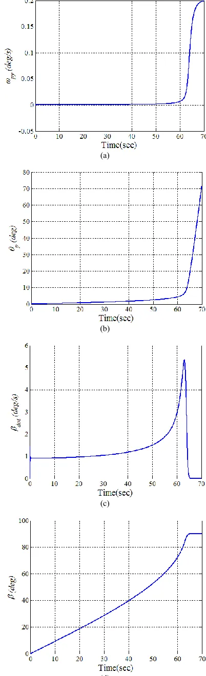
1) Simulation results
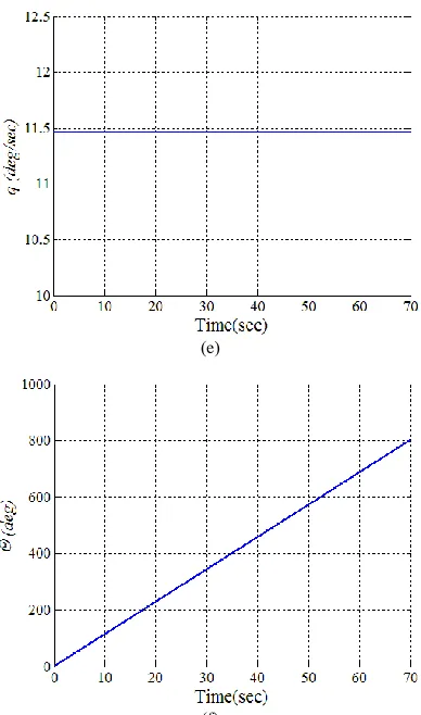
Evaluate the response of the system under the constant angular velocity of the body (11.5°/sec) in this open-loop simulation. The platform does not deviate as long as there are gyroscopic effects. When the angle for output axis of gyro [ ] reaches about 90°, the gyro no longer has the necessary efficiency and is colloquially locked. The gyroscopic effects will be lost and the platform will become unstable. The simulation results can be seen in Fig. 4.
( a )
( b )
( c )
( e )
( f )
Fig. 4. (a) Absolute angular velocity of stable platform in line with y axis; (b) absolute angle of stable platform in line with y axis; (c) relative angular velocity between floating gyro and stable platform; (d) relative angle between floating gyro and stable platform; (e) absolute angular velocity of body in line with y axis; (f) absolute angle of the body in line with y axis (Euler angle).
B. Closed-loop system response
The derivative proportional controller [PD] is used in this mode and input control gains are selected as follows with the provisions of stability and several manual adjustments:
Simulation in this mode is equivalent to open-loop simulations in which the controller begins to act and stabilizes the platform and damps the disturbance.
2) Simulation results
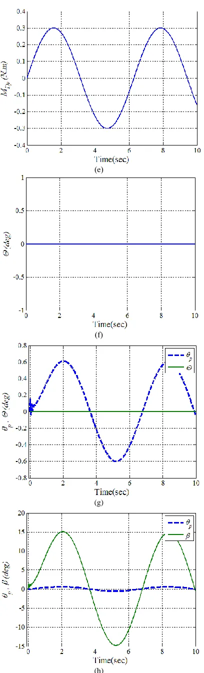
The closed-loop system response is evaluated under the influence of an external periodic torque applied around the stability axis on the stable platform. The intruder outer torque is considered to be a sinusoidal wave with amplitude of 0.3 Newton meters. As observed, the gyro output axis angle also makes a periodic change to provide the signals necessary to neutralize the intruder torque. The oscillating angle of the platform in this mode is caused by the feedback that enters the controller from it. The simulation results can be seen in Fig. 5.
( a )
( b )
( c )
( e )
( f )
(g)
(h)
Fig. 5. (a) Absolute angular velocity of stable platform in line with y axis; (b) absolute angle of stable platform in line with y axis; (c) relative angular
velocity between floating gyro and stable platform; (d) relative angle between floating gyro and stable platform; (e) absolute angular velocity of the body in line with y axis; (f) absolute angle of the body in line with y axis (Euler angle); (g) comparison between absolute angle of stable platform in line with y axis and absolute angle of the body in line with y axis (Euler angle) (h) comparison between absolute angle of stable platform in line with y axis and relative angle between floating gyro and stable platform.
VIII. CONCLUSION
The present article is an introduction to the structure and function of single axis force stabilizers and the possible applications of this type of stabilizer. The equations governing single axis gyroscopic force stabilizers were analyzed and its structure and performance were simulated in MATLAB/SIMULINK. The results of simulation were evaluated in the closed-loop and open-loop modes. In open loop mode, the performance of the system under 11.5O/sec angular velocity of body is evaluated. In closed loop mode, system response is evaluated under the influence of an external sinusoidal wave with amplitude of 0.3 Newton meters torque which is applied around the stability axis of the stable platform. The results indicate that the stabilizer behavior for the conditions defined in the simulations is what would be expected under real applications.
The use of these platforms under different environmental conditions and the direct influence of environmental conditions on the behavior of the stabilizer components must be considered. Evaluation of the effects of environmental conditions such as temperature and humidity on the behavior of the components and overall performance of these platforms is a promising area of future research.
REFERENCES
[1] R. Salloum, B. Moaveni and M.R., Arvan, “Robust position control design for an electromechanical actuator with time delay,”
The 22nd Iranian Conf. on Electrical Engineering (ICEE), Tehran, Iran, 2014, pp. 1227-1232.
[2] R. Salloum, M.R. Arvan and B. Moaveni. (2014). Robust Lead Compensator Design for an Electromechanical Actuator Based on H∞ Theory. Automatic Control and Information Sciences, 2 (3), pp. 53-58.
[3] J. Fei and Y. Yang. (2012). Comparative study of system identification approaches for adaptive tracking of mems gyroscope. Int. Journal of Robotics and Automation, 27 (3), pp. 1-8.
[4] M. Masten. (2008). Inertially stabilized platforms for optical imaging systems tracking dynamic targets with mobile sensors.
IEEE Trans. Control Systems Magazine, 28, pp. 47-65.
[5] J.M. Hilkert. (2008). Inertially stabilized platform technology concepts and principles. IEEE Trans. Control Systems Magazine, 28, pp. 26-46.
[6] P.J. Kennedy and R.L. Kennedy. (2003). Direct versus indirect line of sight (LOS) stabilization. IEEE Trans. Control Systems Technology, 11, pp. 3-15.
[7] H. Khodadadi, M. Jahed Motlagh and M. Gorji, “Robust control and modeling a 2-DOF inertial stabilized platform,” Int. Conf. on Electrical, Control and Computer Engineering, Pahang, Malaysia, 2011, pp. 223-228.
[9] M. Abdoa, A. Toloei, A. Vali and M.R. Arvan. (2014). Modeling, control and simulation of cascade control servo system for One axis gimbal mechanism. Int. Journal of Engineering, 27, pp. 157-170.
[10] W. Ji, Q. Li, B. Xu, J.j. Tu and D.a. Zhao, “Cascade servo control for LOS stabilization of opto-electronic tracking platform design and self-tuning,” Int. Conf. on Information and Automation, Zhenjiang, China, 2009, pp. 1034-1039.
[11] J. Eklånge, “Design and Implementation of a Test Rig for a Gyro Stabilized Camera System,” M.S. Thesis, Dept. Electrical. Eng., Linköping Univ., Linköping, Sweden, 2006.
[12] L. Zhi-qiang, Z. Zhi-yong, Z. Qing-kun and F. Da-peng. (2013). Parameter identification of inertially stabilized platforms using current command design. Springer, 20, pp. 342–353.
[13] F. Branes. (1971). Stable Member Equation of motin for a Three-Axis Gyro stabilized Platform. IEEE Trans. on Aerospce and Electronics System, AES-7 (5).
[14] T. Aruga, N. Wada, A. Ming, N. Kurakane, M. Satoh, H. Takeuchi and S. Tazoe, “Development of a Small Tracking Camera System for Mobile Platforms,” Int. Conf. on Information and Automation, Zhuhai/Macau., 2009, pp. 939-944.
[15] A. Ashwin, R. Seshia, H. Tim and M. Stephen, “An Integrated Micro Electromechanical Resonant Output Gyroscope,” In Proceedings, 15th IEEE Micro Electro Mechanical systems Conf., Las Vegas, NV, Jan. 20-24, 2002.
[16] A. Ashwin and B. Seshia. (1996). Integrated Micromechanical Resonant Sensor for Inertial Measurement Systems. Indian Institute of Technology, Bombay.
[17] P.B. Ljung. (1997). Micro machined Angular Rate Sensor. PhD thesis, University of California, Berkeley.
[18] U.G. Trends. (1997). Modern Gyroscope Technology. Martinenko Education Journal of Sorosovski, No 11, Russian.
M.S. Mirzajani Darestani was born in Rudbar, Gilan, Iran in 1989. He received the M.S. degree in electronics engineering from the Islamic Azad University, Tehran Central Branch, in 2015. He is Ph.D. student in electronics engineering in Islamic Azad University, Arak Branch.