Computational study on stress & deflections
of Glass Epoxy Composites
T. Prasad1, R. Naresh Kumar Goud2, P.Chinna Sreenivas Rao3 and K. Srinivasa Chalapati4
I. INTRODUCTION
Composite are gaining wider acceptance for use on board warships and submarines due to number of advantages viz. high strength to weight ratio, ability to be molded into complex shapes, better EMI performance, absence of corrosion palliatives which otherwise are source for electronic and magnetic signature. Composite materials made from E-Glass fibers and epoxy resins have become very popular as a radome material due to its outstanding transparency to microwave and having good mechanical properties.
The increasing popularity of the material for underwater application are posing great difficulties to the designer to select right combination of composition & shape of radome due to the complex nature of the structure and the loading conditions for the useful operation life.
1
Anurag Group of Institutions, Hyderabad, India.
2Anurag Group of Institutions, Hyderabad, India.
3Anurag Group of Institutions, Hyderabad, India.
4Anurag Group of Institutions, Hyderabad, India.
e-ISSN:2278-621X
Abstract: Composites find their applications in many fields. One of the major being the air craft
Industry where it is used for the manufacture of the radomes. The manufacturing of the E-glass epoxy composite in the laminate form involves the design of the mould and the manufacturing of a composite laminate using the 8mould. The laminate is manufactured by table tap pre-preg method manually and then subjected to a compressive load for thorough distribution of resin in respective lamina and then finally subjected to curing by gradual heating towards high temperature in a closed control thermal oven. Then test the manufactured laminate for its tensile strength and Young’s modulus.
Mechanical properties of composite materials are influenced by several process etc. Conducting the tests on standard specimens and evaluating mechanical properties is the most important aspect in design of composite material applications. The micro-mechanics and failure mechanism of composite material is very complex compared to the conventional isotropic materials. Depending on the reinforcement, composition content & its percentage, appropriate theory & failure mechanism can be considered for designing the radome made of E-Glass epoxy composite.
The word composite – means consisting of two or more distinct parts. Thus a material has two or more chemically distinct constituents or phases, on a macro scale, having a distinct interface separating them, may be considered a composite material. Only when the constituent phases have significantly different physical properties and thus the composite properties are noticeably different from the constituent properties that we have come to recognize these materials as composites. Modern structural composites, frequently referred to as Advanced Composites are a blend of two or more components, one of which is made up of stiff, long fibers, and the other, a binder or matrix which holds the fibers in place. The fibers are strong and stiff relative to the matrix and are generally orthotropic (having different properties in two different directions). The fiber, for advanced structural composites, is long, with aspect ratio (length to diameter ratios) of over 100.
II. METHODOLOGY
Any material in an elongated form such that it has very high length to diameter ratio is called a fiber. Fibers are much stiffer and stronger than the same material in bulk form. Materials have actual strengths which are several magnitudes lower than the theoretical strengths. This difference is due to the inherent flaws in the material. As the fibers become smaller in diameter, it reduces the chances of an inherent flaw in the material, thereby the strength is increased. The different types of fibers are,
a) GLASS FIBERS
These fibers graded as E, A, C, S, Z, M & D.
‘E’ glass is electrical grade which is having high bulk electrical resistivity and high surface resistivity.
‘A’ glass in one which is having high alkali content and of very limited use.
‘C’ glass is a chemical quality and used for corrosion resistance to acids.
‘S’ glass has higher strength and elastic modulus than E glass.
‘Z’ glass is used to reinforce the cement products.
‘M’ glass has high value of young’s modulus but specific strength is low.
‘D’ glass has low dielectric loss value and hence is specifically suited for high performance electronic applications radomes etc.
direct melt process, the molten glass is introduced into platinum bushing, where the molten glass is gravity fed through a multiplicity of holes in the base of the bushing.
b) CARBON AND GRAPHITE FIBERS
Strictly speaking, the term “graphite” fibers is a misnomer since there is no true graphite crystal structure in the fibers. The term ‘graphite fiber’ is used to describe fibers that have a carbon content in excess of 99% whereas the term “carbon fiber” describes fibers it have a carbon content of 8095%. The carbon content is a function of the heat treatment temperature.
c) ARAMID FIBERS
Aramid fiber is a generic term for a specific type of ‘aromatic polyamide fiber’. It is also defined as a manufactured fiber in which the fiber forming substance is a long chain synthetic polyamide in which at least 85% of the amide linkages are attached directly to two atomatic rings, compared to nylons and other conventional polyamides since the latter polymers contain few if any aromatic groups in the main chain of the polymer.
III.RESULTS AND DISCUSSIONS:
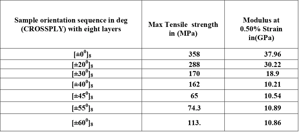
Tensile tests were performed on balanced symmetric laminates of (± 0)8 , (± 20)8 , (± 30)8 , (± 40)8 , (± 45)8 , (± 55)8 ,(± 60)8 degree orientation. The tensile test were performed on the laminates which are made as per the ASTM D-638 specifications.
The test was performed in the CIPET, Hyderabad laboratories and saint GOBAIN VETROTEX India private Ltd. Quality control laboratories, Hyderabad and DRDL Hyderabad laboratory. The consolidated test results are furnished in table No. 5.1.
Sample orientation sequence in deg
(CROSSPLY) with eight layers Max Tensile strength in (MPa)
Modulus at 0.50% Strain
in(GPa)
[±00]8 358 37.96
[±200]8 288 30.22
[±300]8 170 18.9
[±400]8 162 10.21
[±450]8 65 10.54
[±550]8 74.3 10.89
[±600]8 113. 10.86
5.5.1 Experimental Setup for Deflection test:
The deflection to be induced in the specimen is estimated by conducting the deflection tests on the specimens of laminates [±0]8,[±20]8,[±30]8,[±40]8,[±45]8,[±55]8 and [±60]8. The photograph of the experimental setup is shown in Fig. No. 5.2 and the schematic diagram is shown in the Fig.No.5.3.The experimental set up is instrumental in estimating the deflection to be induced to simulate the required bending stress in the specimen subjected to flexural bending .
Fig. No. 5.2 Experimental setup for deflection test
Making use of the Experimental setup, deflection test is performed on the [±0]8, [±20]8, [±30] 8,[ ±40] 8,[ ±45]8,[±55]8 and [±60]8 specimens. As the total load could not be simulated on deflection test due to experimental setups’ geometrical constraints, the experimental results were extrapolated to estimate actual deflection. This is done origin lab software. The deflection test results and estimated deflection are furnished in the following sections 5.5.1 (a) to (g) on the specimens .The specifications of these specimens are furnished in the table No. 5.2.
Table no. 5.2 Specification with respect to the orientation of stacking.
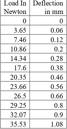
5.5.1 (a) Deflection test on [±0]8
Table no 5.3 Load versus Deflection experimental data of [±00]8 specimen
Load In Newton Deflection in mm 0 0 3.65 0.06 7.46 0.12 10.86 0.2 14.34 0.28 17.6 0.38 20.35 0.46 23.66 0.56 26.5 0.66 29.25 0.8 32.07 0.9 35.53 1.08 S.No of Test Sample orientation sequence in deg (CROSSPLY) effective length of specimen in mm. thickness of specimen in mm number of layers
-5 0 5 10 15 20 25 30 35 40 0.0 0.2 0.4 0.6 0.8 1.0 1.2 D ef le ct ion I n m m
Load In Newtons on [± 00
] Laminate
Equation y = a + b*x Adj. R-Square 0.96796
Value Standard Error
B Intercept -0.09438 0.03523
B Slope 0.02997 0.00164
Fig. no 5.4 Load versus deflection curve of cantilever beam for [± 00] Balanced symmetric laminate
The deflection behaviour is almost linear, the equation of the fitted line is y = .02997x -0.09438
From this equation the approximate deflection ‘y’ to be induced to simulate bending load ‘x’ of 320 Newton is given by,
y = 320*.02997 -0.09438
Then ‘y’ (Deflection) = 9.5mm
The eccentricity given at the hinge, δ = x*2.1mm = 9.5* 2.1mm = 20 mm
5.5.1 (b) Deflection test on [±200]
8 specimen:
Table no 5.4 Load versus Deflection experimental data of [±200]8 specimen
-5 0 5 10 15 20 25 30 35
0.0 0.2 0.4 0.6 0.8 1.0 1.2
Def
lectio
n
in
m
m
Load In Newton
Equation y = a + b*x Adj. R-Square 0.99839
Value Standard Error B Intercept -0.02829 0.00815 B Slope 0.03252 3.93817E-4
Fig. No 5.5 Load versus Deflection of [±200]8 specimen
IV.CONCLUSIONS
1) Tensile tests were performed on balanced symmetric laminates of (±0)8, (±20)8, (±30)8, (±40)8, (±45)8, (±55)8, (±60)8 degree orientation. The maximum tensile occurs at (±0)8, orientation, minimum tensile stress at (±0)8.
2) Making use of experimental set up, deflection test is performed on the (± 0)8 , (± 20)8 , (± 30)8 , (± 40)8 , (± 45)8 , (± 55)8 ,(± 60)8 specimens. As the total load could not be simulated on deflection test due to experimental setups geometrical constraints, the experimental results were extrapolated to estimate actual deflection.
V. REFERENCES
1. Balram gupta, “Aerospace Materials” Vol. 1 to 5, S Chand and company.
2. “Aalysis and performance of fiber composites”, Agarwal BD and Boutman LJ, John Wiley and sons.
3. “Mechanics of composite materials”, Jones RM, Mcgraw Hill. 4. Titterton G, “Aircraft materials and process”, 5 edition.
5. Greenhalgh RJS, Baynham E, Evans D, Canfer S, Robertson S, Morrow D, Temple S. Strength of epoxy-resin-based insulation systems in transverse tension and shear using two novel test pieces. International Journal of Adhesion & Adhesives 2003;23(6):485–494.
6. Peter Ifju P, Myers D, Schulz W. Residual stress and thermal expansion of graphite epoxy laminates subjected to cryogenic temperatures. Composites Science and Technology 2006;66(14):2449–2455.
7. Saniee FF, Majzoobi GH, Bahrami M. An experimental study on the behavior ofglass–epoxy composite at low strain rates. Journal of Materials Processing Technology 2005;162–163(1):39– 45.
9. Cindy Foreman, “Advanced composites”.

![Fig. no 5.4 Load versus deflection curve of cantilever beam for [± 00] Balanced symmetric laminate](https://thumb-us.123doks.com/thumbv2/123dok_us/1403049.1652429/6.612.184.431.70.247/load-versus-deflection-curve-cantilever-balanced-symmetric-laminate.webp)
![Table no 5.4 Load versus Deflection experimental data of [±200]8 specimen](https://thumb-us.123doks.com/thumbv2/123dok_us/1403049.1652429/7.612.193.420.116.291/table-load-versus-deflection-experimental-data-of-specimen.webp)
