IJIRSE/Vol 3. Iss. 6/ Page 231
Satellite Image Resolution Enhancement Using
Multi Scale Decomposition and Anisotropic Diffusion
N. Aruna1, P. Prasanna Murali Krishna2 1 PG Student, 2 Associate Professor
Dept. of ECE , Dr. SGIET College of Engg., Markapur, Andhra Pradesh, India. [email protected] [email protected]
Abstract— Nowadays satellite images are used in many applications such as astronomy, geographical information systems and geosciences studies. Due to low frequency nature of satellite images it may appear as blurred images. To increase the frequency of these images, image resolution enhancement techniques are used. In this paper we propose a new satellite image resolution enhancement technique based on Multi Scale Decomposition and Anisotropic Diffusion. In the proposed resolution enhancement technique uses Dual Tree Discrete Wavelet Transform (DT-DWT) to decompose an input low resolution satellite image into different sub bands. Combine the filtered high frequency sub bands and the low resolution input image using Inverse DT-DWT to reconstruct a resolution enhanced image. Then, apply the Anisotropic Diffusion (an Edge preserving smoothing filter) to this image for denoising the image and to cater for the artifacts generated by DT-DWT. The quantitative (Peak signal to noise Ratio and Mean square Error) visual results show the superiority of the proposed technique over the conventional resolution enhancement techniques.
Keywords – Resolution Enhancement (RE), Interpolation, Dual Tree Discrete Wavelet Transform (DT-DWT), Edge Preserving Smoothing (EPS).
I. INTRODUCTION
Tree-IJIRSE/Vol 3. Iss. 6/ Page 232
Discrete Wavelet Transform (DT-DWT) is shift (or rotation) invariant and directional selective. In this letter, a Multi scale Decomposition and Edge preserving Smoothing based image resolution enhancement (DTDWT-EPS) technique is proposed which generates sharper high resolution image. According to the quantitative and visual results, the proposed technique outperforms the aforesaid state of art and conventional techniques for Satellite Image enhancement.
II. IMAGE RESOLUTION ENHANCEMENT TECHNIQUES
Several research papers and reports were addressed the subject of resolution enhancement and PSNR improvement of an image by using several image resolution enhancement techniques and algorithms. Wavelets play a significant role in multi resolution analysis. In this section we review past work relevant to the image resolution enhancement. A literature survey in this area finds a significant amount of work in knowing about different techniques employed in enhancing the resolution of the images.
A. DISCRETE WAVELET TRANSFORM
DWT decompose the image into different subband images namely LL, LH, HL and HH. The frequency components of the sub bands cover the full frequency spectrum of original image. Interpolation can be applied to these four subband images. In wavelet domain the low resolution image is obtained by low pass filtering of the high resolution image. The low resolution image (LL-subband) is used as input in this resolution enhancement process. Interpolation carried out using adjacent pixel algorithm. In parallel the low resolution input image is also interpolated separately. Finally Inverse DWT has been applied to combine high frequency subband images and interpolated input image to achieve a high resolution output image.
B. STATIONARY WAVELET TRANSFORM
The SWT is wavelet transform algorithm is similar to that of DWT, just the size of sub bands produced by SWT is same as that of input image size because it not use down sampling as it is used in DWT, Which is created to remove lack of translation invariance of DWT. Information loss occurs due to down sampling in each of the DWT sub bands caused in the respective sub bands. SWT also known as undecimated wavelet transform. As like DWT, the SWT also divides the input image into different sub bands. The SWT is an inherently redundant scheme as the output of each level of SWT contains the same number of samples as the input. So for a decomposition of N level there is a redundancy of N in the wavelet coefficients.
C. DUAL TREE –DISCRETE WAVELET TRANSFORM
IJIRSE/Vol 3. Iss. 6/ Page 233
Figure-1: Dual Tree Discrete Wavelet Transform (DT-DWT) structure
The DT-DWT of an image produces two complex valued low frequency subband images and six complex valued high frequency subband images. The high frequency subband images are the result of direction selective filters. They show peak magnitude responses in the presence of image features oriented at ±75º, ±15º, and ±45º directions with 4:1 redundancy. After that the interpolation is applied to the high frequency subband images. In wavelet domain the low resolution image is obtained by low pass filtering of the high resolution image. Therefore, in place of using low frequency subband images which contain less information than the original input image, we are using the input low resolution image for the interpolation. By interpolating the input image by β/2 and the high frequency subband images by β and then applying Inverse DT-DWT operation to get super resolved image. This is due to the fact that the interpolation of the isolated high frequency components will preserve more than the interpolating the input image directly.
III. INTERPOLATION
Interpolation has been widely used in image processing widely. In mathematics, Bicubic interpolation is an extension of cubic interpolation for interpolating data points on a two dimensional regular grid. The interpolated surface is smoother than corresponding surfaces obtained by bilinear interpolation or nearest-neighbor interpolation. Bicubic interpolation can be accomplished using either Lagrange polynomials, cubic splines, or cubic convolution algorithm. In image processing, bicubic interpolation is often chosen over bilinear interpolation or nearest neighbor in image resampling, when speed is not an issue. In contrast to bilinear interpolation, which only takes 4 pixels (2×2) into account, bicubic interpolation considers 16 pixels (4×4). Images resampled with bicubic interpolation are smoother and have fewer interpolation artifacts.
Suppose the function values and the derivatives , and are known at the four corners , , , and of the unit square. The interpolated surface can then be written
IV. EDGE PRESERVING SMOOTHING
The main loss of an image after being resolution enhanced by applying interpolation is on its high frequency components, which is due to smoothing caused by interpolation. The problem of image smoothing is to reduce undesirable distortions, due to the presence of noise or the poor image acquisition process and that negatively affects analysis and interpolation processes, while preserving important features such as homogeneous regions, discontinuities, edges and textures. In order to increase the quality of super resolved image, it is essential to preserve all the edges in an image. Filtering is perhaps the most fundamental operation of image processing and computer vision. Examples of edge preserving smoothing are Bilateral Filter, Guided Filter and Anisotropic Diffusion. Guided filter is an explicit image filter, derived from a local linear model; it generates the filtering output by considering the content of a guidance image, which can be the input image itself or another different image.
Anisotropic diffusion: Nonlinear anisotropic diffusion filtering is a procedure based on nonlinear evolution partial differential equations which seeks to improve images qualitatively by removing noise while preserving details and even enhancing edges. In particular, Perona and Malik proposed the following nonlinear diffusion approach to image filtering. It produces a family of parameterized images, but each resulting image is a combination between the original image and a filter that depends on the local content of the original image.
IJIRSE/Vol 3. Iss. 6/ Page 234
where denotes the Laplacian, denotes the gradient, is the divergence operator
and is the diffusion coefficient. controls the rate of diffusion and is usually chosen as a function of the image gradient so as to preserve edges in the image. Pietro Perona and Jitendra
Malik pioneered the idea of anisotropic diffusion in 1990 and proposed two functions for the diffusion coefficient:
the constant K controls the sensitivity to edges and is usually chosen experimentally or as a function of the noise in the image.
V. PROPOSED TECHNIQUE
Figure-2: Block diagram of proposed DT-DWT-EPS Image Resolution Enhancement Algorithm
In the proposed algorithm (DT-DWT-EPS), we decompose the LR input image (for the multichannel case, each channel is separately treated) in different sub bands by using DT-DWT as shown in Fig.1 (i.e. image coefficient sub bands and wavelet coefficient sub bands). Image coefficient subband contains low pass filtered image of the LR input image, therefore, high frequency information is lost. To cater for it, we have used the LR input image instead of image coefficient sub bands. The HF sub bands are interpolated by factor β using the bicubic interpolation (having good approximation capabilities) and combined with the β/2 interpolated LR input image. Then we apply the Inverse DT-DWT to these filtered sub bands along with the interpolated LR input image to reconstruct the super resolved image Although the DT-DWT is almost shift invariant, however, it may produce artifacts after the interpolation of wavelet coefficient sub bands. Therefore, to cater for these artifacts Edge Preserving Smoothing (EPS) filter is used. All interpolated wavelet coefficient sub bands are passed through the EPS filter. The resolution enhancement is achieved by using directional selectivity provided by DT-DWT, where the high frequency sub bands contribute to the sharpness of the high frequency details in six different directions, such as edges.
The Mean square Error (MSE) represents the cumulative squared error between the reconstructed and the original image. The low value of MSE leads to low value of error.
∑ ∑[ ( ) ( )]
IJIRSE/Vol 3. Iss. 6/ Page 235
PSNR usually expressed in terms of logarithmic decibel value. PSNR adjusts the quality of the image which the higher the PSNR refers to the better quality is the image.
The PSNR be calculated as
(
)
Where „MAX‟ is the maximum fluctuation in input image, for an 8-bit image, value of „MAX‟ is 255. Thus the MSE and PSNR are two error metrics used to compare image reconstruction quality.
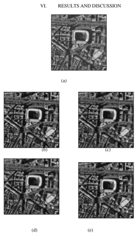
VI. RESULTS AND DISCUSSION
(a)
(b) (c)
(d) (e)
Fig. 3. (a) Original LR image (b) DT-DWT-RE (c)DT-DWT-EPS(Bilateral). (d)DT-DWT-EPS(Guided). (e)DT-DWT-EPS (Anisotropic Diffusion).
IJIRSE/Vol 3. Iss. 6/ Page 236
such as MSE and PSNR. Fig.3 shows the RE images of input image. To ascertain the effectiveness of the proposed DT-DWT-EPS algorithm over other wavelet domain RE techniques, different LR optical images obtained from the Satellite Imaging corporation web page were tested. Note that the LR image has been obtained by down sampling the original HR image by a factor 4.
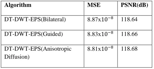
TABLE. 1
Comparisons of the Existing and Proposed Techniques for the Input image shown in Fig. 3(a).
Algorithm MSE PSNR(dB)
DT-DWT-EPS(Bilateral) 8.87x 118.64
DT-DWT-EPS(Guided) 8.83x 118.66
DT-DWT-EPS(Anisotropic Diffusion)
8.81x 118.68
Table-1 shows the proposed techniques provide improved results interns of MSE and PSNR as compared with other techniques. It can be clearly shows that the results of the proposed algorithm DT-DWT-EPS(Anisotropic Diffusion) are much better than the RE images obtained using other techniques. Not only visual comparison but also quantitative comparisons are confirming the superiority of the proposed method.
CONCLUSION
This paper proposes a novel image resolution enhancement technique based on DT-DWT and EPS filter. The technique decomposes the LR input image using DT-DWT. Wavelet coefficients and Input image were interpolated using the Bi-cubic interpolator. DT-DWT is used since it is shift invariant as well as directional selective and generates fewer arty facts; as compared with DWT. EPS (Anisotropic) filtering is used to preserve the edges and de-noising the image and to further enhance the performance of the proposed technique in terms of MSE and PSNR. Simulation results highlight the superior performance of proposed technique. In future we work to extend this project to get the good efficiency and accurate results.
REFERENCES
[1] M. Z. Iqbal, A. Ghafoor, and A. M. Siddiqui “Satellite Image Resolution Enhancement Using Dual-Tree Complex Wavelet Transform and Nonlocal Means” IEEE Geoscience and Remote Sensing Letters, vol. 10, no. 3, pp. 451-- 455, MAY 2013
[2] R. C. Gonzalez, R. E. Woods and S. L. Eddins, “Digital Image Processing,” 2nd Edition, Pearson Education, New Jersey, 2002.
[3] H. Demirel and G. Anbarjafari, “Discrete wavelet transform-based satellite image resolution enhancement,” IEEE Trans. Geosci. Remote Sens.,vol. 49, no. 6, pp. 1997–2004, Jun. 2011.
[4] H. Demirel and G. Anbarjafari, “Image resolution enhancement by using discrete and stationary wavelet decomposition,” IEEE Trans. Image Process., vol. 20, no. 5, pp. 1458–1460, May 2011.
[5] I. W. Selesnick, R. G. Baraniuk, and N. G. Kingsbury, “The dual-tree complex wavelet transform,” IEEE Signal Prcess. Mag., vol. 22, no. 6, pp. 123–151, Nov. 2005.
IJIRSE/Vol 3. Iss. 6/ Page 237
[7] H. Demirel and G. Anbarjafari, “Satellite image resolution enhancement using complex wavelet transform,” IEEE Geosci. Remote Sens. Lett.,vol. 7, no. 1, pp. 123–126, Jan. 2010.
[8] M. Protter, M. Elad, H. Takeda, and P. Milanfar, “Generalizing the nonlocal-means to super-resolution reconstruction,” IEEE Trans. Image Process., vol. 18, no. 1, pp. 36–51, Jan. 2009
[9] .M. Nagao and T. Matsuyama. “Edge preserving smoothing”. Computer Graphics and Image Processing, 9:394–407, 1979.
[10] C. Tomasi and R. Manduchi, “Bilateral filtering for gray and color images,” in Proc. IEEE Int. Conf. Computer Vision, Jan. 1998, pp. 836–846.
[11] J. Weickert, Anisotropic Diffusion in Image Processing, B. G. Teubner Stuttgart, 1998.
[12]. P. Perona and J. Malik, Scale Space and Edge Detection Using Anisotropic Diffusion,Proc. IEEE Comp. Soc. Workshop on Computer Vision, Miami Beach, November 30 –December 2, 1987, IEEE Computer Society Press, Washington, pp. 16 – 22, 1987.
Authors Profile:
N. Aruna received B.Tech Degree in Electronics&Communication Engineering from MBES college of Engg, Ambajogai in 2003. Currently she is pursuing M.Tech at Dr.SGIET Engg College, Markapur. Her research interests include Image Processing and signal processing.