Development of a Advanced Computerised
Biometric Attendance Logging System for
Institutions of Higher Learning
Vinesh Thiruchelvam
Shaima Wahid
School of Engineering, School of Engineering,
Asia Pacific University, Asia Pacific University,
Kuala Lumpur, Malaysia. Kuala Lumpur, Malaysia.
E-mail: [email protected] E-mail: [email protected]
Abstract — The desertion presents an advanced wireless fingerprint based attendance logging system that consists of an electronic fingerprint device and desktop attendance management application that shall be updated based on the data received from the hardware wirelessly through the Xbees communication modules. The system design and components have been selected carefully ensuring maximum efficiency. The system was successfully implemented, results were obtained, each function was tested and compared with theoretical results.
Index Term-- fingerprint, attendance system, Xbees communication, desktop attendance management.
I. INTRODUCTION
Attendance management is the act of managing attendance or presence in the workplace setting which motivates staff attendance and minimizes loss due to employee downtime. It is one of the most basic and important management links. This will ensure that a real-time staff attendance can be reflected, which can be easily monitored by competent authorities and in this study it is for Asia Pacific University (APU).
Staff attendance management is considered as a major part of today’s human resource systems that take organization towards better human resource practice, systems and excellence. Hence regular attendance and punctuality are expected of all employees or staff in a work setting.
In particular, when the type of the job is very sensitive and might impact the future of many people such as staff or lecturers in universities, schools or institutions. If any of the staff is absent that might hamper, mess or postpone many of the university and students operations and activities, especially if that staff member is a lecturer. If the lecturers do not attend their classes regularly or they are late then their performance and ability to complete the prescribed curriculum as required and on time will be affected which will have an impact on the student learning process. Thus, in any institutions, schools or universities it is very necessary to keep regular track on attendance of staff.
Attendance management has traditionally been approached using time clocks and timesheets, but this traditional paper-based method can easily allow impersonation or lost and
proves through life failure and absence of accuracy in manual voting system.
Attendance systems with the use of Biometrics proved to be the most popular, mature, and reliable and secured among all other technologies used in automatic personal identification and the fingerprint recognition method is the preferred type of all available biometrics (face shape, fingerprints, voice and eye). Since it is unique to each individual (Even identical twins do not carry identical fingerprints) [1], they do not change over time, and fingerprints have high matching accuracy rates and inherent ease the acquisition of the numerous sources.
Hence, in this project, an advanced wireless fingerprint-based attendance system for Asia Pacific University (APU) is proposed. The proposed system is combining three different
technologies; EMBEDDED SYSTEMS, BIOMETRIC
recognition and WIRELESS technology. The proposed system has been improved to be distinguished from the existing ones in many different aspects such as type of network used to transfer data, components used, programing languages used and adding more features such as creating desktop application for records management and analyzing trendy reports automatic generation. The research main concern is to ensure APU continuous operation, increase in staff productivity, improving the enterprises management efficiency by strictly monitoring and reporting staff attendance regularity with the use of an efficient and flexible embedded wireless system [2].
II. METHODOLOGY
The system implementation broadly consists of two main parts i.e. the hardware design (fingerprint device) and the software development (desktop application). However, the implementation and construction of the hardware prototype, software development and the system operating procedure of the proposed system would be explained in more details.
The implementation of the proposed system mainly consists of two main stages: hardware implementation stage and software implementation stage.
A. Hardware Implementation
1. Construction Details
Once the components were carefully selected, the datasheet of each component has been studied in order to know the power requirements of each component and all the technical details that would help to construct the system.
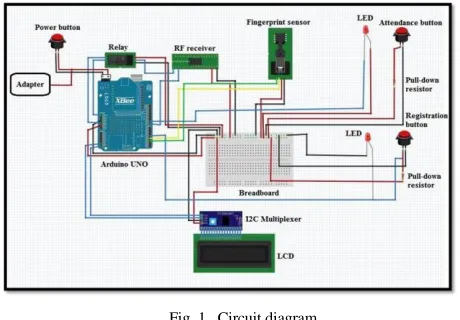
Fig. 1. Circuit diagram
The hardware circuit diagram consists of the main board Arduino Uno microcontroller that interfaces and controls all the other system components; Adafruit optical fingerprint sensor, the RF 4 channels remote control kit, Xbee series 2 wireless module, and its compatible shield LCD display, three push button switches (ON/OFF, registration and attendance switches), two LEDs indicators for the switches and Relay. Besides that, the circuit includes some other supporting components for the main elements, as each one of the switches is connected with 1k ohm resistor as well as the PCP board that would be used to make a common power input source (Vcc) and common ground coming from the main Arduino board to connect all the components through. However, this circuit is powered up using an adapter power supply which converts AC current to 5V DC.
The Xbee shield is stuck on the top of the Arduino Uno board making use of the TX and RX serial communication ports and allowing all the other components to be connected to the Arduino pins through the available pins on the top of the Xbee shield. So, the TD (transmit data) green wire and RD (receive data) yellow wires of the Adafruit fingerprint sensor are connected to the Arduino Uno digital pins 2 and 3 respectively. While the power input red wire and the black wire are plugged into the common power input and ground on the PCP board.
The RF remote control kit has been utilized in this project for making a wireless remote, which takes the input signal from the transmitter remote (by Administrator) through to the receiver RF receiver module connected to Ardunio. The output from the receiver is used to drive the Relay that acts as a reset
button from a distant place as well as to activate the registration mode through Arduino (by coding).
The power and ground pins of the receiver module are pulled to the common Arduino power input and ground on the PCP. Whereas the output pin D3 of the RF receiver is connected to Arduino digital Pin 8 and D1 is connected to the enable pin of the Relay IN pin. So, when the digital output D1, is high the relay will operate (the remote control is pressed and the signal is sent to the corresponding pin D1 on the receiver). While, the pins on the other side of the relay are connected as follow, the NO (normally open connection) pin is connected to the reset pin on the Arduino and the COM (common connection pin) is connected to the ground such that it acts like a switch that is normally open, then when the relay is triggered/operate the NO connects to COM by the electromagnet inside the relay and supply to the load is provided (activated the reset pin on the Arduino [3].
On the other hand, the circuit has three main push button switches; power or ON/OFF button that is connected directly to the power supply adapter, registration and attendance buttons that are used to control (activate and deactivate ) the registration and attendance mode.
Xbee series 2 module was mounted on the top of the Xbee shield which is stuck on the Arduino board. Power is taken from the 5V pin of the Arduino and regulated on-board (shield) to 3.3VDC before being supplied to the XBee [4].
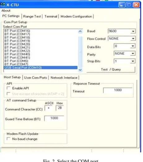
However, in order to achieve two- way point to point communication in order to implement the system methodology and accomplish the objectives. Two Xbee modules were used, one has to be configured as a coordinator and another one as a router. However, configuration of the Xbee modules has been done at AT mode using X-CTU software and the steps are shown below:
Xbee configuration as a coordinator:
Fig. 2. Select the COM port
Then, “Test/Query” option was pressed. Once it works and the port descriptions were displayed, the “Modem Configuration” Tab was selected.
Next, the “Always Update Firmware” was clicked, followed by “Read” to get data from XBee.
After that, “under Function Set select “ZIGBEE COORDINATOR AT”, preferable PAN ID for example “1234” was set and the SH and SL ID were recorded in order to set Router module.
Then, “Write” option was clicked in order for X-CTU terminal to start loading the parameters that have been set.
Xbee configuration as a router:
At first, plug the XBee S2 module on XBee USB to Serial port adapter and plug the USB cable to computer, then run the X-CTU software.
Next, “ZIGBEE ROUTER AT” was selected under Function Set, PAN ID was set “1234” (should be similar to the coordinator), and the DH and DL address were keyed based on the SH and SL recorded from coordinator module (DH: 13A200, DL: 408C1470).
After that, “Write” option was clicked and X-CTU had started loading the parameters which were being set.
Once the configuration was done, both Xbee modules are paired together and can talk to each other once they get powered (data is sent and received from one Xbee to another) [5].
2. Programming
The software used to program the hardware is Arduino (version 1.5.4) and the code was written in C language. Once the code was written and built up successfully, it has been
verified before it was fed to the Arduino and worked successfully.
The code starts by declaring the libraries, variables and functions as well as allocating the microcontroller ports to the fingerprint serial communication ports. The TD (transmit data) pin from the fingerprint is allocated to be connected to pin 2 on the UNO microcontroller and RD (receive data) pin is allocated to be connected to pin 3 in the UNO microcontroller.
The Xbee wireless serial communication baud rate was defined to be 9600, while the fingerprint serial baud rate was selected to be 57600 the communication needs to be faster as shown below;
Fig. 3. Xbee Communication Coding
There are basically three main modes in the code, Registration/enrollment mode, Attendance/verification mode and the Select mode which is out of the two main modes.
All the three modes are written inside one main loop that acts like a class which assigning the 3 switches to 3 variables:
Fig. 4. Loop Switching Coding
Fig. 5. Registration Coding
The getFingerprintEnroll (id) function, is first to get the ID from the serial port (coming from desktop) as an array, to convert it to integer and to pass it to the hardware in order to allow staff to place his/her fingerprint for registration. It first waits and asks the staff member to place his/her fingerprint, then this fingerprint would be tested against one of 4 cases: in case the fingerprint capturing exposed to any type of error it would not accept it. Otherwise, it would ask the staff member to remove his/her finger, and then to place back again to capture more features and increase reliability. Then if no error was occurred, fingerprint features were captured and stored successfully and it would be bound along with the perceived attendance ID (ID stored).
The second mode in the system is the
attendance/verification mode, which is activated once the attendance switch (assigned to rp) is being low. Once this mode is ON, (“Attendance Mode”) message would be displayed on the screen and the staff member/user would be asked to place his fingerprint for attendance logging. After that the getFingerprintIDez() would be called.
Fig. 6. Verification Mode Coding
The getFingerprintIDez() is a function in which three other pre-made functions from Adafruit library are called; getImage() , finger.image2Tz() and fingerFastSearch().
Through these functions the captured fingerprint image would be obtained and processed under different cases to ensure that image is clear and has no errors. Then the
fingerprint would be searched and compared with all the pre-stored images (1 to N searching technique) considering validation in each step to avoid any type of error or mismatched.
After all these functions are implemented, if the fingerprint is verified and matched successfully, match function would be implemented to send back the attendance ID of the particular staff member to the desktop application in order to record the attendance in the database.
B. Software Implementation
The software implementation parts include the development of the desktop application that is used for the attendance management. As well as the development of the database that is used to store the staff details and attendance recorders to retrieve them back when it is needed.
However, the desktop application interface has been developed with C#.NET programming language using C# 2010 Express. Where, the database has been developed with MySQL using EasyPHP local server.
Database structure
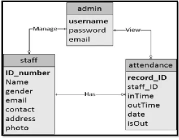
Fig 7 shows the ERD (Entity relationship diagram), which represents the database structure:
Fig. 7. Entity relationship diagram
Mainly there is one user (administrator) that can affect the database. There are three tables in this database (APU), a table that contains administrator information; a table that contains staff information and a table that contains the staff attendance records. Admin has the privilege to manage the staff information and view their attendance and each of the staff has attendance records in the attendance table.
Desktop Application
Fig. 8. Main Admin Login Page Platform
The important component in this page is the login button and the code for it is shown below. When the administrator presses on the login, it first checks and ensures that the username and password fields are not empty. Otherwise, it would not allow the admin to log in and a message saying ("please enter the username/password") would be displayed.
Fig. 9. Admin Logging Coding
C. Working Principle
As a new staff member comes and before proceeding to the hardware station he/she has to go to the administration counter to be registered in the desktop database through desktop application interface. Then to proceed to the fingerprint device station along with one authorized admin to complete registration and to enroll his fingerprint.
Once the staff member presses the registration switch, the system will wait for activation from the authorized admin who carries the RF remote control (transmitter module). This remote control set acts as another push button, so once the authorized administration pressed the assigned key on the remote, the signal would be sent to the corresponding pin on the RF receiver module and thus activates the registration mode.
When the registration mode is activated, it first requests for an ID from the desktop by sending ‘W’ character to desktop in order to store the fingerprint along with this ID (attendance ID).
Once the desktop application interface received this message it would automatically assign attendance ID for the particular staff member and send it to the hardware to be tied and stored along with the fingerprint image. Once this is done, this new staff member can enroll his finger and once enrolling is done successfully the hardware device would send the following confirmation message ‘S’ the desktop application in order for the staff data to be stored. However, this registration process is a onetime process for every new staff member.
In each working day the staff member has to log his attendance twice a day in order to record time in and out time out. So, if the staff member presses the attendance button s/he would be directly allowed to place his fingerprint, once staff member places his/her fingerprint, a fingerprint sensor captures the images, extracts its features and compares the captured image with all the pre-stored fingerprint images in the sensor memory (1 to N matching). Then, if it is matched with one of them, the assigned attendance ID for the particular fingering is sent to the desktop application in order to store the attendance record for that particular staff member and the ID would also be displayed on the LCD for the staff to ensure that his/her attendance is recorded successfully. Otherwise, if the placed finger is not pre-registered in the system, it would not be identified by the system and it will keep asking to place a fingerprint.
All these system processes and transmission of data between hardware device and desktop software are only allowed if the wireless communication is ON. If there is any problem in the connection between them there will be a notification message on the tray and the connection status on the desktop application configuration window would be changed to ‘Not Connected”, so that the administrator can fix the problem and reestablished the connection.
III. RESULTS
This section presents the results which define and demonstrate that the system has successfully accomplished its objectives. Thus, first the circuit diagram design as shown in figure 1, was implemented practically and it the components were connected exactly in the same way. The implemented system prototype is shown in Figure 10 below;
The picture above shows the prototype of the electronic fingerprint device (hardware part) that mainly used for fingerprint enrollment/ registration and fingerprint verification for staff attendance records. So, figures below show some of the important LCD output results of the implemented prototype for both functions; registration and attendance logging:
A. Registration process:
As mentioned above, after the registration mode is activated by both registration switch button and RF remote, the system will wait for ID form the desktop to allow staff member to enroll his/her fingerprint.
Then, once the attendance ID is being revived, the system will ask the staff to place his finger twice for accurate capturing and if the two enrolled finger were same, the registration process is done and the revived ID that would be stored along with the fingerprint for attendance is displayed on the LCD screen. Otherwise, in case if any error occurred registration will not be allowed and an error message would be displayed on the LCD.
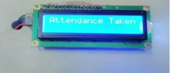
B. Attendance Logging:
Once the staff member presses the attendance button to record his/her attendance, the attendance mode will directly be activated and system will ask the staff member to place his/her finger for attendance:
Fig. 11. Successful Attendance Logging
On the other hand, the desktop application was successfully developed and can handle staff registration and management functions.
Once all the fields are filled and all the information is in the correct format a new staff member will be registered successfully and data will be stored in the database in STAFF table as shown in figures below:
Fig. 12. Successful staff registration on the desktop Application
C. Daily Report
Daily reports will be obtained by selecting the required date, while the monthly reports will be generated after insertion of the required month and year. However, to ensure that the coding done and developed functions (daily report and monthly trending report) are working fine, they were tested using data of 20 staff members for complete two months (40 working days) [7], under different time conditions: on time, late in, early out or no record at all.
Fig. 13. Daily Report Test result
D. Monthly Reports
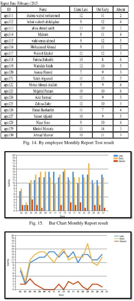
The figures below show the obtained monthly attendance report for February month:
Fig. 14. By employee Monthly Report Test result
Fig. 15. Bar Chart Monthly Report result
Fig. 16. Line Chart Monthly Report result
Based on the entered data for the test, all the different types of obtained monthly reports from the test give affirmative results. As the same data entered to or received to from database are being displayed [8].
The two charts for monthly trending reports shown in Fig 15 and 16 clearly illustrate the total number of staff absents,
latecomers and early leavers for each working day in February month in accordance with the total staff number. Even though, both charts are displaying same data, but each gives different analysis. The bar chart gives the actual number of each category per day to easily compare them, while the line chart gives a clear overview of the overall performance of staff during February month and it can show the change in staff performance over the same period of time for the three different groups (absents, latecomers and early leavers) which can be easily measured [9].
The only possible error that might occur in this report is that the displayed staff data is not accurate and this could happen if the data from the hardware are wrong, not received on time or was due to any problem in the wireless communication. However, the probability of error occurrence is very low.
IV. CONCLUSION
With the great advancement in technology, many electronic attendance management systems have been emerged and help to increase organizations’ productivity and make administrators’ life easy. The main purpose of this system was to monitor the staff attendance accurately and automatically analyse their performance in a very short time and to avoid all different type of errors. This project meant to develop more reliable, fast and efficient system wireless fingering attendance system with low cost. The implemented system was tested and proved that it was reliable, efficient and secured enough to be real time life and does not malfunction at least for some period of a few years. This was made possible by achieving all the objectives and aim.
V. REFERENCES
[1] Cappelli, R. et al. (2007) Fingerprint Image Reconstruction from
Standard Templates. EEE Transactions on Pattern Analysis and Machine Intelligence, 29 (9). p .1489-1503.
[2] AbedelKarim, A. & AbdelQader, A. (2014) Electronic Student
Attendance Recording System. International Journal of Computers & Technology, 4 (2). p. 220-224.
[3] Gomathi.B & Priyadarshini.S, V.(2013) Modernized Voting Machine
using Finger Print Recognition. International Journal of Scientific & Engineering Research, 4 (5). p. 156-161.
[4] Hangzhou Zhian . (2008) ZFM-20 Series Fingerprint Identification
Module . 1st ed. Cambridge: Cambridge University.
[5] Sudhanshu Pandey, Mithilesh Kumar Chaubey, Saurabh Kumar
Srivastava, Roma Pal,& KIT Kanpur. (2012) Xbee BASED Device Control with Feedback. International Journal of Advanced Technology. 2(2). p .1-5.
[6] Shoewu .O, &. Idowu. O.A .(2012) Development of Attendance
Management System using Biometrics. Science and Technology. 13(1). p .300-307.
[7] Wale, S. & Patil, S.(2014) Indigenous Development of Automated
Wireless Fingerprint Attendance System. International Journal of Scientific & Engineering Research, 11(2).
[8] YanWang, Liu, H, & Feng, J. (2010) The Design of an Intelligent Security Access Control. Scientific Research (SCIRP), 01(1). p. 30-33.
[9] Sairam, K. (2002) Bluetooth in Wireless Communication. IEEE
Communications Magazine, 5(4). p. 96.
[10] Karthikeyan.A,& Sowndharya.J.(2012) FINGERPRINT BASED
IGNITION SYSTEM. International Journal Of Computational Engineering Research. 2(2). p. 236-243.
[11] Kristensen T. (2012) Two Different Regimes of Fingerprint