Evolvement of Computer Aided Software Engineering (CASE) Tools: A
User Experience
G.K.A. DIAS
University of Colombo School of Computing, University of Colombo, Sri Lanka
ABSTRACT
Computer Aided Software Engineering was originally used in 1982. Several CASE tools were introduced to the market in late 1980s. None of the CASE tools that were introduced during this time fully incorporate a methodology. CASE tools that were available during ‗90s usually confirm to some system development methodology. They automate part or all of the supported methodology. In the mid-nineties, with the rise of Object Orientation, the traditional CASE tools were perceived as a failure by many people. The OO CASE tools introduced during this time had the notation battle to fight. This made comparing the tools quite difficult because people were more comparing the diagramming notations than the tool's features themselves. "OO notation wars" ended after the introduction of UML in 1997. New set of CASE tools that supported UML diagrams were introduced after 1997. These CASE tools were categorized as Upper, Lower and I-CASE tools. After 2001, agile software development support was also incorporated in to CASE tools. Latest versions of some of the CASE tools currently available support the Model Driven Engineering (MDA) and Executable UML(xUML). This paper discusses the evolvement of CASE tools –a user experience from 1982 onwards to date.
Keywords: Computer Aided Software Engineering, Upper CASE, Lower CASE, I-CASE, Model Driven Engineering, xUML.
1. INTRODUCTION
Computer Aided Software Engineering was origi nally used by Nastec Corporation of Southfield, Michigan in 1982. Several CASE tools were introduced to the market in late 1980s. The evolvement of CASE tools can be categorized in to three eras; namely ‗80s, ‗90s and present CASE tools. They are described below with author‘s experience.
2. CASE TOOLS IN ‘80S
The term CASE was originally used by Software Company, with their original integrated graphics and text editor called GraphiText. This Editor also was the first
microcomputer-based system to use hyperlinks to cross-reference text strings in documents. GraphiText's successor product, DesignAid was the first microprocessor-based tool to logically and semantically evaluate software and system design diagrams and build a data dictionary. [1]
The next entrant into the market was Excelerator introduced in 1984 by Index Technology in Cambridge, Mass. While DesignAid ran on Convergent Technologies and later Burroughs Ngen networked microcomputers, Index launched Excelerator on the IBM PC/AT platform. Excelerator became popular and was the best seller in 1989. According to the PC Magazine of January 1990, well over 100 companies were offering nearly 200 different CASE tools. Other packages that were discussed in this article were Analysis/Designer toolkit from Yourdon, Automate Plus from Learmonth & Burchett Management systems, DesignAid from Nastec Corp., IEW/Analysis and Design Workstations from KnowledgeWare, Pose from Computer Systems Advisers, teamwork from Cadre Technologies, Visible Analyst Workbench from Visible Systems Corp., and vsDesigner from Visual Software. [2]
Analysis of the above CASE Software is shown in the following Table 1 and Table 2.
Table 1: Analysis of CASE tools in 1989 Set 1 [2]
Case Tools
Po
se
Visib
le
Ana
ly
st
Wo
rk
b
en
c
h vS
De
sig
n
er
Ana
ly
st
/De
sig
n
er
To
o
lk
it
Te
a
m
wo
rk
List Price
$
5
9
5
/M
o
d
u
le
$
5
9
5
/M
o
d
u
le
$
9
9
5
0
$
2
3
5
0
$
4
9
9
5
Techniques Supported
Process Specs Y N Y Y Y Physical Database Y N N N N Structure Chart Y N Y Y Y Jackson Structure N N Y N N Warnier-Orr-charts N N Y N N
Nassi-Schneiderman charts
N N N N N
Flow Charts N Y N Y Y Action Charts Y N Y N N Decision Tables or
Trees
N N N N Y
State transition N N Y Y Y
Table 2: Analysis of CASE tools in 1989 Set 2 [2]
Case Tools
Auto
m
a
te
Pl
u
s
De
sig
n
Aid
Ex
ce
ler
a
to
r
IEW/Ana
ly
st
a
n
d
De
sig
n
Wo
rk
sta
tio
n
List Price
$
6
9
0
0
$
6
9
0
0
$
8
4
0
0
$
8
6
2
5
Techniques Supported
Entity Relationship Y Y Y Y Data Model Y Y Y N Logical Database Y Y N Y Data Flow Y Y Y Y Decomposition N Y Y Y Process Specs Y N Y Y Physical Database Y Y N N Structure Chart Y Y Y Y Jackson Structure N Y Y Y Warnier-Orr-charts N Y N Y Nassi-Schneiderman
charts
N Y N Y
Flow Chart Y Y Y Y Action Chart N Y N Decision Tables or
Trees
N Y Y N
State Transitions N Y N N
3. CASE TOOLS IN ‘90S
3.1 Introduction
CASE tools that were available (including the later versions of some of the CASE tools mentioned in 2.0) during 90‘s usually confirm to some system development methodology. They automate part or all of the supported methodology. When using these CASE tools the organizations had to consider whether the features of a CASE tool fit the methods they use in system development or whether they wish to modify
their methods to obtain CASE benefits.[3][4] Some of the PC CASE tools that were available during this time are given in Table 3. [4][5]
Table 3: Some of the PC CASE tools that were available in early ‘90s. [4][5]
Product Vendor Hardware
Analyst Designer ToolKit
Yourdon IBM PC and Compatibles
Automate + LBMS IBM PC and Compatibles
CASE 2000 Nastec Corp. IBM PC Compatibles, VAZ Workstations Excelerator Index
Technologies
IBM PC Compatibles, Sun, Apollo
Information Engineering Workbench
Knowledge Ware IBM PC Compatibles, IBM MVs, DEC VAX Teamwork Cadre
Technologies
Sun,Apollo,VAX, HP 9000
Deft Deft Inc. Macintosh
Oracle *CASE Oracle Corp. IBM PC and Compatibles, Sun
A variety of methodologies were used in CASE tools during this time. Some of them are given below and are listed in Table 4 with their supportive techniques.
HIPO (Hierarchy and Input, Process and Output Methods)
LSDM (Learmouth Structured Development Method)
SSADM (Structured Systems Analysis and Design Method)
-YSM (Yourdon Structured Method)
CASE Method (The Method used by Oracle Corporation)
JSD (Jackson Structured Design Method)
Following are the techniques that were popular during that time.
Table 4: Some of the System Development Methodologies used in ‘90s with their supportive techniques [4]
Design Methods
Techniques
HIPO FHD,IPO charts
LSDM DFD,ERD,Data Analysis, ELH SSADM DFD,ERD,Data Analysis, ELH YSM DFD,ERD, STD,SC
CASE Method
DFD,ERD, Data Analysis, FHD, Matrix Plotting
JSD PSD
The author had experience with three of the tools mentioned in Table 3.
They were Automate +, Deft and Oracle Case. They are briefly described below with Simple CASE, a CASE tool developed by the author for teaching purposes.
3.2 Automate Plus (Version 3.0)
Automate + was a commercially available CASE tool for IBM PC and compatible machines. The only system development methodology supported by this tool was LSDM. Hence Automate + provided only the techniques that are needed for LSDM methodology. SSADM was a more popular derivative of LSDM. Two main notations for DFDs (Yourdan/Demarco and Gane & Sarson) were supported by the tool whereas only the Benchman/Chen (arrow head) and Martin (Crowsfeet) notations for ERD were supported. A User had to select the notations required at the installation time. It also supported drawing of Structure Charts and Physical design. Version 3.0 of Automate + supported only up to the system design stage. Supported Logical Design, Physical Data Design and Physical Process design. [6][4]
3.3 Deft (Version 3.1)
Deft was a commercially available CASE tool for Macintosh PCs. It does not support any of the traditional design methodologies directly. It supported the techniques DFD,ERD and PSD. For DFDs it supported Yourdan/Demarco and Gane and Sarson notations where as for ERD it supported Benchman/Chen, Martin and IRM notations. [7]
The form editor in Deft allowed a user to design application screens, forms and reports. The Design compiler in Deft ensured design integrity by analyzing design diagrams for syntactical and logical correctness. Deft dictionary allowed the user to check and repair a dictionary, and merge dictionaries from different users. Compiled designs could be interfaced by the Deft Gateway module with the users host applications development environment. Gateway module also
allowed the user to ‗reverse engineer‘ an Ingress SQL or QUEL database the user had already created. [7][4]
3.4 Oracle *CASE (CASE * Designer ver. 1.1 ,
CASE *Dictionary ver. 5.0)
Oracle *CASE was a commercially available CASE tool for SUN workstations, IBM PC‘s and compatibles. Oracle *CASE supported only a method call CASE *Method. It supported four techniques namely DFD,ERD, FHD and Matrix Plotter. Dictionary module of the tool supported the following features.[8]
- Holds development definitions and modules
- Uses an Oracle relational database repository
- Can be accessed through the diagrams
- Can generate default application, customize forms and reports
- Facilities to cross check completeness and accuracy of the modules.
The interface of Oracle *CASE is very hard to learn. It supports only Gane & Sarson notation for DFDs and Oracle *CASE notation (its own) for ERD.
3.5 Simple CASE
Sri Lanka being a developing country, a number of factors prevented widespread use of the commercially available CASE tools during ‗90s. They are namely the high cost of the initial investment for the package, and the steep learning curve their users have to undergo in order to exploit the package. The wide variety of notations that were available during this time and the limited subset of design techniques supported by most commercially available CASE tools is another negative point. These problems were major problems for educational environment where the high cost cannot be justified and the steep learning curve is unacceptable. [7][8][6]
4. PRESENT CASE TOOLS
4.1 Introduction
In the mid nineties, with the rise of Object Orientation, the traditional CASE tools were perceived as a failure by many people. The first OO CASE tools had the notation battle to fight, which made comparing the tools quite difficult because people were more comparing the diagramming notations than the tool's features themselves. "OO notation wars" ended by Rumbaugh, Booch, and Jacobson after getting together on UML and ended the controversy. After the introduction of UML in 1997 this was resolved. [9]
4.2 CASE tools with UML support
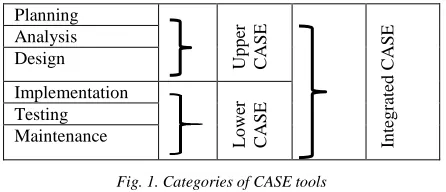
New set of CASE tools that supported UML diagrams were introduced after 1997. Some of the present CASE software packages are used primarily to support the analysis workflow to create integrated diagrams of the system and to store information regarding the system components (often called upper CASE). There are also CASE software that support the design workflow that can be used to generate code for database tables and system functionality (often called lower CASE). Integrated CASE, or I-CASE, contains functionality found in both upper CASE and lower CASE tools. They support tasks that happen throughout the system-development process. Figure 1 illustrate these categories of CASE tools. [10]
Planning
Up
p
er
CASE
In
teg
ra
ted
CAS
E
Analysis Design
Implementation
Lo
we
r
CASE
Testing Maintenance
Fig. 1. Categories of CASE tools
The following Table 5 summarizes the features of these categories of case tools. [1][10]
Table 5: Summary of features related to categories of CASE tools.
Upper CASE Supports Business modeling
They do not support implementing , testing and maintenance
Eg. Diagramming tools such as UML tools which support drawing of UML diagrams.
Lower CASE Do not support Planning,
Analysis and Design
Eg. Tools to support code generation.
Integrated CASE They are helpful in all the stages of SDLC, from Requirement gathering to Testing and documentation
Many good CASE tools are available in the marketplace now to support object-oriented systems development. The following are some of the popular tools.
Enterprise Architect, Poseidon, Visual Paradigm, Rational Rhapsody
Rational Rose which supports the Rational Unified Process was very popular in early millennium. The author had experience with Rational Rose 2002 which consists of a very user friendly UML diagramming editor. This version also has a code generation and reverse engineering facility which supports C++, Visual C++ and Visual Basic. [11]
More examples of currently available CASE tools can be found in Wikipedia.org [12].
The benefits of using CASE are numerous. With CASE tools, tasks can be completed and altered much faster, development information is centralized, and information is illustrated through diagrams, which are easier to understand. Potentially, CASE can reduce maintenance costs and improve software quality, and enforce a discipline for the users. Many modern CASE tools that support object-oriented systems development supports round-trip engineering (a development technique). Round-trip engineering supports not only code generation but also the reverse engineering from code to UML diagrams. For example, a tool that supports UML diagrams can generate programming code that can be modified by the programmers, at which point the UML diagrams will need to be changed as they no longer accurately represent the code. Most tools for UML also supports the generation of UML diagrams from code. In this way, the system can evolve via diagrams and via code. This is called round-trip engineering.[1] [10] The central component of any CASE tool is the CASE repository or data dictionary. The CASE repository stores the diagrams and other project information, such as screen and report designs, and it also keeps track of how the diagrams fit together. For example, most CASE tools will give a warning if you place a field on a screen design that does not exist in your structural model. As the project evolves, project team members perform their tasks using CASE components. [10]
4.3 CASE tools with Agile development support
practice-based for effective modeling and documentation of software-based systems. Even though Agile has its critics and is not recommend for all software development projects, the methodologies have gained a strong hold in recent years. Currently there are number of CASE tools that supports Agile Development. Some of the earlier case tools that supported UML based methodologies have included modules to support agile development or plug-ins to their latest versions. They also can connect with other tools. [13][14][15][16].
4.4 Other Categories and features of CASE tools
Computer-aided software engineering (CASE) tools assist software engineering managers and practitioners in all the activities associated with the software process. They automate project management activities, manage all work products produced throughout the process, and assist engineers in their analysis, design, coding and testing work. CASE tools can be integrated within a sophisticated environment. Some authors have categorized the CASE tools into the following categories. [17]
- Project Management Tools
- Analysis and Design Tools
- Object-Oriented Software Engineering
- Testing Tools
- Formal Methods
- Client/Server Tools
- Web Engineering Tools
- Reengineering Tools
4.5 CASE Tools supporting Model Driven
Engineering(MDA), Executable UML(xUML)
MDE is an approach to software development where models rather than programs are principal outputs of the development process. The programs that execute on hardware/software platform are then generated automatically from the models. MDE allows engineers to rethink about systems at a high level of abstraction. This is without worrying about the details of their implementation. This will speed up the design and implementation and reduces the likelihood of errors. In order to support model driven engineering, software engineers need to construct graphical models with information about the ways in which operations defined in the models are implemented. This is possible with the subset of UML 2 called executable UML or xUML. [18][19]
Andro MDA, Star UML, BoUML, MagicDraw and Enterprise Architect are some of the CASE tools that supports MDA. Details about the Tools that support
MDA can be found in Madhavi Karanams publication [20].
Executable UML (xUML of xtUML) method is the successor to the Shlaer-Mellor method. It is both a software development method and highly abstract software language. The fundamental notion behind model-driven engineering is that completely automated transformation of models to code should be possible. To achieve this, there should be a possible way to Construct Graphical models whose semantics are well defined and also need to a way of adding information to graphical models about the ways in which the operations defined in the model are implemented. This is possible using a subset of UML 2, called Executable UML. [10][18] To create an executable subset of UML, the three model types are needed.[18]
1. Domain models (Domain Chart ) : Provides a view of the domain being modeled, and the dependencies it has on other domains.
2. Class models (Class diagram) : Define the classes and class association for domain.
3. State models (Statechart diagram) : Defines the states, events, and state transition for class or class instance. Addition to above models, there is another element to represent the dynamic behavior of the model. The dynamic behavior of the system may be specified declaratively using the UML‘s action language. Action language is like a very high-level programming language where able to refer to objects and their attributes and specify actions to be carried out. [18]
Examples of a tools that supports xUML can be found in modeling-languages.com and ‗Papyrus‘ web site [21][22]
5. CONCLUSION
CASE tools that were introduced before mid 1990s support traditional methodologies or do not fully incorporate a methodology. New set of CASE tools that supported UML diagrams were introduced after 1997. Some of the currently available tools support Agile Development as well as Model Driven Engineering and xUML.
REFERENCES
[1]
https://en.wikipedia.org/wiki/Computer-aided_software_engineering, Last Accessed January, 2017
[2] PC Mag 1990, https://books.google.lk/books?id=ySO 4VbD0-mcC
[3] G.K.A. Dias, Dr. E.K. Seneviratne , Prof Alec Gray , ―An, Architecture for a Simple CASE tool‖, Proceeding of SEARCC 1995, Colombo. ISBN -955-9155-03-2, Sarvodaya Vishvalekha
[4] G.K.A. Dias ,―Prototype Computer Aided Software Engineering Tool for teaching purposes‖, MPhil Project Report ,University of Wales , 1995.
[5] A.S. Fisher, ―CASE –Software Development Tools‖, John Wiley & Sons Inc., 1988
[6] Learmouth & Burchett Management Systems, ‗Automate Plus Manual‘ Version 3.0 User manual, 1986.
[7] Def Inc.,‘DEFT User‘s Manual‘ , version 3.1, 1987 [8] Oracle Corporation, UULTD, Training Series, ‗System
Design and Generation Techniques with Oracle CASE Course Notes‘, 1992
[9] Hubert A. Johnson, Laura Wilkinson, ―Case tools in object-oriented analysis and design‖, Journal of Computing Sciences in Colleges archive, Volume 19 Issue 2, Pages 306-313, December 2003
[10]Alan Dennis, Barbara Haley , David Tegarden, Systems analysis design, UML version 2.0 : an object oriented approach, 5th edition, John Wiley & Sons, 2015 [11]Terry Quatrani, ―Visual Modeling with Rational Rose
2002 and UML‖, Addison Wesley, 2002
[12]List of Unified Modeling Language Tools, https://en.wikipedia.org/wiki/List_of_Unified_Modelin g_Language_tools, Last Accessed January, 2017 [13]Paul Krill, ―Developer picks: 7 hot tools for agile
development‖, InfoWorld, Oct 29, 2013
[14]To agility and beyond: The history—and legacy—of agile development https://techbeacon.com/agility- beyond-history%E2%80%94-legacy%E2%80%94-agile-development, Last Accessed January, 2017 [15]https://en.wikipedia.org/wiki/Agile_software_developm
ent, Last Accessed January, 2017 [16]
https://www.visual- paradigm.com/solution/agiledev/agile-development-tool/, Last Accessed January, 2017
[17]Computer Aided Software Engineering, http://www.mhhe.com/engcs/compsci/pressman/olc_lin kedcontent/casetools.htm#test, Last Accessed January, 2017.
[18]I. Sommerville, "Software Engineering,", Boston, Addison-Wesley,10th edition, 2016
[19] https://en.wikipedia.org/wiki/Model-driven_engineering#Tools
[20]Madhavi Karanam, MDA Tool Support for Model Driven Software Evolution: A Survey, International Journal of Computer Science Engineering (IJCSE), pp 11-17, 2015
[21] http://modeling-languages.com/list-of-executable-uml-tools/, 2015
[22]Papyrus for Real Time (Papyrus-RT), https://projects.eclipse.org/projects/modeling.papyrus-rt, 2017.
![Table 3: Some of the PC CASE tools that were available in early ‘90s. [4][5]](https://thumb-us.123doks.com/thumbv2/123dok_us/1327407.1640913/2.612.80.295.81.554/table-pc-case-tools-available-early-s.webp)