R E S E A R C H P A P E R
Open Access
A practical person authentication system
using second minor finger knuckles for door
security
Daichi Kusanagi, Shoichiro Aoyama, Koichi Ito
*and Takafumi Aoki
Abstract
This paper proposes a person authentication system using second minor finger knuckles, i.e., metacarpophalangeal (MCP) joints, for door security. This system acquires finger knuckle patterns on MCP joints when a user takes hold of a door handle and recognizes a person using MCP joint patterns. The proposed system can be constructed by attaching a camera onto a door handle to capture MCP joints. Region of interest (ROI) images around each MCP joint can be extracted from only one still image, since all the MCP joints are located on the front face of the camera. Phase-based correspondence matching is used to calculate matching scores between ROIs to take into consideration deformation of ROIs caused by hand pose changes. Through a set of experiments, we demonstrate that the proposed system exhibits the efficient performance of MCP recognition and also show the potential possibilities of second minor finger knuckles for biometric recognition.
Keywords: Finger knuckle, Biometrics, Phase-only correlation, Door security, Metacarpophalangeal joint
1 Introduction
A hand has a lot of biometric traits such as fingerprint, palmprint, finger/palm vein, finger knuckle, and hand geometry. Among such traits, a finger knuckle is a rel-atively new biometric trait in contrast with famous bio-metric traits such as face, fingerprint, and iris [1]. An outer surface of a finger has three knuckles: a distal inter-phalangeal (DIP) joint, a proximal interinter-phalangeal (PIP) joint, and a metacarpophalangeal (MCP) joint as shown in Fig. 1. Kumar et al. [2] categorized three finger joints into major and minor finger knuckles, where a DIP joint is a first minor finger knuckle, a PIP joint is a major fin-ger knuckle, and an MCP joint is a second minor finfin-ger knuckle. It is easy to capture such patterns on a finger knuckle by a camera. This advantage allows us to develop a flexible and compact biometric authentication system. A finger knuckle is also expected to be distinctive as well as a fingerprint and a palmprint, although statistical analy-sis using a huge dataset has to be required to demonstrate the uniqueness of finger knuckle patterns [2]. This paper
*Correspondence: [email protected]
Graduate School of Information Sciences, Tohoku University, 6-6-05, Aramaki Aza Aoba, Sendai, Japan
focuses on the use of finger knuckle patterns to develop a person authentication system for door security.
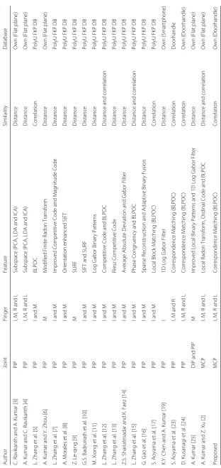
Table 1 shows a summary of researches on finger knuckle recognition. Most researches [3–17] focused on recognition algorithms for texture patterns of PIP joints and evaluated its performance using a public finger knuckle image database such as the PolyU FKP database [18]. The images in the PolyU FKP database are cap-tured under the controlled conditions, since the subject puts his/her finger on fixed blocks in order to reduce the spatial variations and capture clear line features of a fin-ger knuckle. Although it is suitable for researchers to develop a fundamental recognition algorithm using finger knuckle patterns, it may not be practical. Most researches [6, 7, 11–16, 19] employed coding approaches to extract features by applying spatial filters to images and binariz-ing their responses, where a variety of types of Gabor filter are usually used as a spatial filter. Effectiveness of such coding approaches have been demonstrated in iris recognition [20] and palmprint recognition [21]. Some researches [8–10] employed local feature descriptors such as SIFT and SURF, which are used in the field of computer vision. Another approach [5, 12, 15, 17] employed Band-Limited Phase-Only Correlation (BLPOC), which is an
Distal interphalangeal (DIP) joint
Proximal interphalangeal
(PIP) joint
Metacarpophalangeal (MCP) joint
Fig. 1A taxonomy of finger knuckle joints:Blue-colored circlesindicate distal interphalangeal (DIP) joints,green-colored circlesindicate proximal interphalangeal (PIP) joints, andred-colored circlesindicate metacarpophalangeal (MCP) joints
image matching technique using the phase components in 2D Discrete Fourier Transforms (2D DFTs) of given images [22]. Among of them, some researches [15–17] exhibited efficient performance on person authentication using finger knuckle patterns.
There are also a few works on finger knuckle recog-nition under practical situations. Kumar et al. [4] have proposed a finger knuckle recognition algorithm using multiple patterns acquired from the index, middle, ring, and little fingers. They demonstrated that the matching score calculated by combining four PIP joints is effective for person authentication. Cheng et al. [19] have proposed a contactless PIP joint recognition system using a cam-era embedded on smartphones. This was the first attempt to develop a practical person authentication system using PIP joints for smartphones. Therefore, the recognition performance was not necessarily good. Aoyama et al. [23] have proposed a finger knuckle recognition system for a door handle. This system acquired PIP joint patterns when a user takes hold of a door handle and recognized a person using acquired patterns. Hence, the users do not pay attention to the authentication process. This system also used the combined information of the four knuck-les to improve performance of finger knuckle recognition. Kusanagi et al. [24] have developed an improved version of Aoyama’s system by using video sequences.
There are a few works on finger knuckle recognition using MCP and DIP joints compared with PIP joints. Kumar [25] has proposed a finger knuckle recognition algorithm using both major and first minor finger knuckle patterns, i.e., PIP and DIP joints. Combination of two
joint patterns improved performance of finger knuckle recognition. Kumar et al. [2] have also considered the use of texture patterns around MCP joints to identify per-sons. Both works gave us the fundamental investigation of biometric recognition using minor finger knuckle joints, since the performance has been evaluated using images of a hand with the fingers and thumb spread apart put on a flat plane.
This paper focuses on the use of second minor finger knuckles, i.e., MCP joints, for biometric recognition and develop a practical person authentication system using MCP joints. We consider person authentication using MCP joints for a door handle which is inspired by the concept of Aoyama’s system [23]. Aoyama’s system has to embed a camera into a door, since this system captures texture patterns on PIP joints when a user took hold of a door handle, resulting in increasing the cost. Local images around each PIP joint are not always extracted from only one still images suggested by Kusanagi et al. [24]. On the other hand, our proposed system uses MCP joints for per-son authentication. Texture patterns on MCP joints can be captured using a camera attached on a door handle. In this case, MCP joints are located on the front face of the cam-era. Therefore, a local image around each MCP joint can be extracted from only one still image. Phase-based cor-respondence matching [26] is used to calculate matching scores between MCP joint patterns as well as the con-ventional PIP joint recognition systems [23, 24]. Through a set of experiments, we demonstrate that the proposed system exhibits the efficient performance of MCP recog-nition and also shows the potential possibilities of minor finger knuckles for biometric recognition.
The main contributions of this work are summarized as follows:
1. This is the first attempt to use finger knuckle pattern on MCP joints for person authentication in a practical situation.
2. The prototype of a door security system using finger knuckle recognition is developed. The use of MCP joints makes it possible to develop a user-friendly person authentication system for door security.
2 Finger knuckle recognition system for door security
This section describes an overview of the proposed sys-tem. We develop the MCP joint recognition system inspired by the concept of finger knuckle recognition systems for door handles [23, 24].
the thumb. Therefore, DIP joints are not suitable to use person authentication for door security.
The conventional systems using PIP joints consist of a handle, a camera, and a light source, where the camera has to be located so as to face toward PIP joints. When a user takes hold of a door handle, the system captures an image or a video sequence and recognizes a user using PIP joint patterns. The advantage is that the image acquisition process is not intrusive, that is, the user only has to open the door by taking hold of the door handle. The disadvan-tage is that the shape of PIP joints may be varied in each image acquisition due to hand pose variations, resulting in decreasing the recognition performance. In addition, the camera and the light source have to be embedded into the door. Hence, the door has to be refined and it takes much cost.
According to the fundamental investigation by Kumar et al. [2], MCP joints have sufficient distinctiveness for person authentication as well as PIP joints. MCP joints can be captured by attaching a camera onto a door handle and using the ambient light. Therefore, only a lit-tle effort is required to make a system for MCP joint recognition compared with the case of PIP joint recog-nition. Moreover, the variation of MCP joints is smaller than that of PIP joints, when a user takes hold on a door handle.
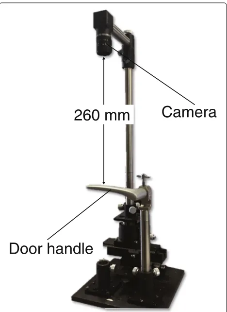
To clarify the potential possibilities of MCP joint recog-nition based on the above consideration, we developed a prototype system for MCP joint recognition as shown in Fig. 2. Table 2 shows the specification of the developed system. The camera is located above the door handle, assuming that the camera is attached on the door. There is no light source, that is, the ambient light is used to take images, assuming the indoor use. Images captured by this system include illumination changes caused only by the ambient light. In practical situation, images include strong daylight, reflection, etc., resulting in images with halation and blur, which significantly decrease recognition perfor-mance. In order to take desired images for MCP joint recognition, an appropriate camera filter and an optional light source have to be used.
3 MCP joint recognition
This section describes the proposed MCP joint recog-nition algorithm, which consists of four steps: (i) image acquisition, (ii) region of interest (ROI) extraction, (iii) ROI matching, and (iv) score fusion. Figure 3 shows the flow diagram of the proposed algorithm. The detail of each step is described in the following.
3.1 Image acquisition
An image of back of a hand including the MCP joints of the index, middle, ring, and little fingers is captured under ambient light conditions using a camera located onto a
Door handle
260 mm
Camera
Fig. 2Overview of the developed system for MCP joint recognition
door handle. Figure 4a shows an acquired input image by the developed system.
3.2 ROI extraction
This step extracts a ROI image from the captured hand image. The position of MCP joints is detected according to the valleys between fingers. The size of images is 1280 × 960 pixels as mentioned in Section 2. The captured image is resized into 640×480 pixels in order to reduce the amount of memory usage and the computation time, assuming that this algorithm is implemented on embed-ded systems. The input image is indicated by f(n1,n2),
where 1≤n1≤480 and 1≤n2≤640.
Table 2Specification of the developed system
Camera PointGrey FL3-U3-13E4C-C [31]
Image size 1280×960 pixels
Lens μ-tron 0420
Focal length 15 mm
Image acquisition
ROI extraction
Matching Matching Matching Matching
Database Image acquisition
ROI extraction
Score fusion
Genuine/Impostor
Enrollment Matching
Index Middle Ring Little
Fig. 3Flow diagram of the proposed MCP joint recognition system
First, both ends of a hand are detected from the input image. The edge image fe(n1,n2) as shown in Fig. 4b is
obtained by applying the Sobel filter tof(n1,n2). The
posi-tion between the camera and the door handle is fixed. Hence, the location of the door handle in the image is known in advance. Letd be the center of the handle in the vertical direction anddbe the coordinate of the end on the handle toward the door in the vertical direction as shown in Fig. 4b. In the case of the developed system,
d=220 andd =300. The horizontal coordinate of both ends of a hand is detected by
el = min
n2|fe(d,n2) >0
, (1)
er = max
n2|fe(d,n2) >0
, (2)
whereelanderindicate the vertical coordinate of left and
right ends of the hand, respectively.dis used to detecter,
since the right-sided end on the handle may be detected as the edge of the hand, ifdis used.
Next, the vertical coordinate of each finger is obtained. To reduce the effect of background noise, the region
f(n1,n2) located around the door handle is extracted
fromf(n1,n2)as follows:
f(n1,n2)=f(n1,n2)|320≤n1≤380,el≤n2≤er. (3)
As mentioned above,f(n1,n2)can be extracted from the
fixed position off(n1,n2), since the relation between the
camera and the handle is fixed in the developed system. The range 320 ≤ n1 ≤ 380 is empirically determined so
as to extract the region between MCP and PIP joints in this paper. Figure 4c shows the extracted regionf(n1,n2).
The intensity value around the boundary between fingers is lower than others, and fingers are located in the ver-tical position. Hence, the boundary between fingers can be detected by projecting pixels off(n1,n2)in the
verti-cal direction. The vertiverti-cal projectionV(n2)off(n1,n2)is
calculated by
V(n2)=
n1
f(n1,n2). (4)
Figure 4d shows the result of vertical projection of
f(n1,n2). The three local minima ofV(n2) are detected
as boundaries between fingers indicated by vm (m =
1, 2, 3), where each index ofmcorresponds to the bound-ary between index and middle fingers, middle and ring fingers, and ring and little fingers, respectively.
Finally, the coordinates of each MCP joint are defined. The edge is tracked from eachvm to the valley between
fingers using the boundary tracking algorithm [27] as shown in Fig. 4e. The coordinate of the end of each val-ley is indicated by wm = (wm1,wm2). We can consider that the geometric relation among MCP joints and valleys is almost the same, since everyone has almost the same structure of a hand. Therefore, the rule-based approach
can be used to detect the coordinates of each MCP joint using valley locationwm. The center coordinate of each MCP joint,u, is defined by
u1 = (u11,u12)=
w11−75,e
l+w1 2
2
, (5)
u2 = (u21,u22)=
w21−75,w
1 2+w22
2
, (6)
u3 = (u31,u32)=
w21−75,w
2 2+w32
2
, (7)
u4 = (u41,u42)=
w31−75,w
3 2+er
2
, (8)
where i = 1, 2, 3, 4 and each indexi corresponds to the index, middle, ring, and little fingers, respectively. The region with 150×150 pixels centered onuiis extracted as the ROI image.
3.3 ROI matching
Phase-based correspondence matching [26] is used to calculate matching scores between ROI images, which employs (i) a coarse-to-fine strategy using image pyramids for robust correspondence search and (ii) a local block matching method using BLPOC. The image deformation is observed in ROI images captured in the different tim-ing due to hand rotation, although ROI images extracted from MCP joints have smaller deformation than those from PIP joints. Such deformation can be approximated by small translations in a local area. Intensity variation can be observed in ROI images due to different illumination condition. BLPOC is one of the image matching methods robust against illumination changes. Therefore, we decide to employ phase-based correspondence matching as well as the conventional PIP joint recognition systems [23, 24]. Fundamentals of POC and BLPOC are briefly described in the following. Consider twoN1×N2 images,f(n1,n2)
andg(n1,n2), where the index ranges aren1= −M1,· · ·, M1(M1>0) andn2= −M2,· · ·,M2(M2>0) for
math-ematical simplicity, and henceN1 = 2M1+1 andN2 =
2M2+ 1. The discussion could be easily generalized to
non-negative index ranges with power-of-two image size. LetF(k1,k2)andG(k1,k2)denote the 2D Discrete Fourier
Transforms (DFTs) off(n1,n2)andg(n1,n2), respectively.
The normalized cross power spectrumRFG(k1,k2)is given
by
RFG(k1,k2)=
F(k1,k2)G(k1,k2)
F(k1,k2)G(k1,k2)
whereG(k1,k2)is the complex conjugate ofG(k1,k2). The
POC functionrfg(n1,n2)is the 2D Inverse DFT (2D IDFT)
ofRFG(k1,k2)and is given by
rfg(n1,n2)=
1
N1N2
k1,k2
RFG(k1,k2)WN−1k1n1W −k2n2
N2 , (10)
where k
1,k2 denotes
M1
k1=−M1
M2
k2=−M2. When two images are similar, their POC function gives a distinct sharp peak. When two images are not similar, the peak drops significantly. The height of the peak gives a good similarity measure for image matching, and the location of the peak shows the translational displacement between the images. The idea of BLPOC is to eliminate meaning-less high frequency components in the calculation of nor-malized cross power spectrumRFG[22]. Assume that the
ranges of the effective frequency band are given byk1 =
−K1,· · ·,K1 and k2 = −K2,· · ·,K2, where 0≤K1≤M1
and 0≤K2≤M2. Thus, the effective size of frequency
spec-trum is given byL1 = 2K1+1 andL2 = 2K2+1. The
BLPOC function is given by
rK1K2
fg (n1,n2)=
1
L1L2
k1,k2
RFG(k1,k2)WL−1k1n1WL−2k2n2,
(11)
wheren1 = −K1,· · ·,K1,n2 = −K2,· · ·,K2, andk1,k2 denotesK1
k1=−K1
K2
k2=−K2. Note that the maximum value of the correlation peak of the BLPOC function is always normalized to 1 and does not depend onL1andL2.
Phase-based correspondence matching consists of a coarse-to-fine strategy using image pyramids and a local block matching method using BLPOC. Letpbe a coordi-nate vector of a reference point in the ROI imageI(n1,n2)
registered in the database. In this paper, the number of ref-erence points is 10×10. The problem of correspondence matching is to find a coordinate vector q in the input ROI image J(n1,n2) that corresponds to the reference
pixelpin the registered ROI imageI(n1,n2). The
proce-dure of phase-based correspondence matching is briefly described in the following.
Step 1: Forl=1, 2,· · ·,lmax−1, create thel -th layer
imagesIl(n1,n2)andJl(n1,n2), i.e., coarser versions
ofI0(n1,n2)andJ0(n1,n2), recursively as follows:
Il(n1,n2) =
1 4
1
i1=0
1
i2=0
Il−1(2n1+i1, 2n2+i2),
Jl(n1,n2) =
1 4
1
i1=0
1
i2=0
Jl−1(2n1+i1, 2n2+i2).
Step 2: For every layerl=1, 2,· · ·,lmax, calculate
the coordinatepl=(pl1,pl2)corresponding to the
original reference pointp0recursively as follows:
pl = 12pl−1 = 12p1l−1,12pl2−1, (12)
wherezdenotes the operation to round the element ofzto the nearest integer toward minus infinity.
Step 3: We assume thatqlmax =plmax in the coarsest
layer. Letl=lmax−1.
Step 4: From thel -th layer imagesIl(n1,n2)and Jl(n1,n2), extract two small imagesfl(n1,n2)and gl(n1,n2)with their centers onpland2ql+1,
respectively. The size of image blocks isW×W pixels.
Step 5: Estimate the displacement betweenfl(n1,n2)
andgl(n1,n2)using BLPOC. Let the estimated
displacement vector beδl. Thel -th layer correspondenceqlis determined as follows:
ql = 2ql+1+δl. (13)
Step 6: Decrement the counter by 1 asl←l−1and repeat from Step 4 to Step 6 whilel≥0.
Step 7: From the original imagesI0(n1,n2)and J0(n1,n2), extract two image blocks with their centers
onp0andq0, respectively. Calculate the BLPOC function between the two blocks. The peak value of the BLPOC function is obtained as a measure of reliability in local block matching. Finally, we obtain the corresponding point pairs and their reliability.
In this paper, we employ parameters:lmax=2,W =48, K1/M1=K2/M2=0.5 for BLPOC.
The matching score is calculated according to the cor-responding point pairs and their reliability. If the relia-bility, i.e., the peak value of BLPOC function, is below the threshold, the corresponding point pair is removed as outliers. We empirically confirmed that high recognition rate is obtained when the threshold is set from 0.2 to 0.5. The best result is obtained when the threshold is 0.3 in this paper. Figure 5 shows an example of correspondence matching. In the case of the genuine pair, the location of corresponding points on the registered image repre-sents deformation between registered and input images. In addition, the reliability of almost all of corresponding point pairs exceeds the threshold. On the other hand, in the case of the impostor pair, the location of correspond-ing points on the registered image is random. This means that the translational displacement between the images cannot be estimated correctly. The reliability of almost all of corresponding point pairs is below the threshold. According to the above, the number of reliable corre-sponding points is used to evaluate the similarity between ROI images. The matching score Si for each finger is defined by
Si= # of corresponding point pairs
a
b
Score = 0.99
Score = 0.11
Fig. 5Result of phase-based correspondence matching for middle fingers.aGenuine pair andbImpostor pair. Theleftis the input image and the
rightis the registered image, wherered dotsindicate corresponding point pairs andblue dotsindicate outliers, i.e., their reliability is below threshold
where i = 1, 2, 3, 4 and each indexicorresponds to the index, middle, ring, and little fingers, respectively.
3.4 Score fusion
The matching scores are calculated from four finger knuckles as mentioned above. To enhance the recogni-tion performance, the final matching scoreSis calculated by combining all the matching scores. There are some approaches to combine matching scores [28]. We decide to use the simple sum rule, taking into consideration the performance and the computation time. The final match-ing scoreSis defined by
S= 4
i=1
Si. (15)
4 Experiments and discussion
This section describes experiments to evaluate perfor-mance of MCP joint recognition using the proposed system.
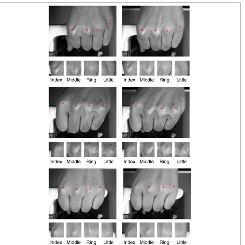
A hand image database is created using the proposed system as shown in Fig. 2. Images are collected from 28 subjects in two separate sessions, where the time interval between the first and second sessions is more than 1 week.
The size of images is 1280×960 pixels as mentioned in Section 2. In each session, five images are captured from the left and right hands. To increase the number of com-binations, we assume that the left and right hand images taken from the same subject are different from each other. The mirror-reversed image of the left hand image is used in the experiments. As a result, the database con-tains 560 images with 56 subjects and 10 different images of each subject. The number of genuine pairs is 2520 (=10C2×56), and the number of impostor pairs is 154,000
(=56C2×10×10).
Index Middle Ring Little
Index Middle Ring Little
Index Middle Ring Little
Index Middle Ring Little
Index Middle Ring Little
Index Middle Ring Little
Fig. 6Images in the database: Images in each row are captured from the same person, andleftandright columnsindicate 1st and 2nd sessions, respectively. Four small images below the acquired hand image are ROI images extracted from each MCP joint andred pointsindicate the detected MCP joints
The performance of the proposed method is compared with the conventional finger knuckle matching methods such as BLPOC [2, 5], CompCode [29], and LGIC [12]. BLPOC is used for PIP joints in [5] and MCP joints in [2]. The BLPOC function between two ROI images is calcu-lated by Eq. (11), and its maximum peak value is obtained as a matching score. CompCode (competitive code) pro-posed by Kong et al. [30] is generated by applying a bank
BLPOC, and the common areas are extracted according to the estimated displacement. A global matching score between common areas is calculated by BLPOC, while a local matching score is calculated by CompCode. The final matching score is obtained by a weighted sum of global and local matching scores. Kumar et al. [2] have suggested that BLPOC exhibited the best performance in finger knuckle recognition of MCP joints from their fundamental investigation. On the other hand, Zhang et al. [12] demonstrated that LGIC exhibited better per-formance than BLPOC in finger knuckle recognition of PIP joints. Hence, we decided to compare the perfor-mance of the proposed method with BLPOC, CompCode, and LGIC.
4.1 Experiment 1
Experiment 1 evaluates recognition performance for each finger such as the index, middle, ring, and little fingers. Figure 7 shows ROC curves for each finger, and Table 3 shows the summary of EERs for each finger and each matching method. BLPOC exhibits low performance for the index, ring, and little fingers, although BLPOC shows good performance on MCP joint pattern recognition in [2]. The global BLPOC-based methods [2, 5] can han-dle only the translational displacement between images. Therefore, the recognition performance is decreased,
since there is nonlinear deformation between ROI images due to hand pose changes. CompCode [29] exhibits the worst performance for the index, middle, and ring fin-gers, since CompCode can handle small translational displacement between images. LGIC [12] show better per-formance than BLPOC and CompCode, since LGIC is a combination of BLPOC and CompCode. On the other hand, the proposed method using phase-based corre-spondence matching exhibits the best performance for all the fingers compared with other methods, since phase-based correspondence matching can take into account nonlinear image deformation. The EER of the little fin-ger is the highest for all the methods. The ROI image of the little finger includes large perspective deforma-tion compared with those of other fingers. The posideforma-tion of the little finger is unstable compared with other fin-gers. As a result, the large deformation is caused even for a small hand pose change. In the case of using PIP joints, EERs of the index and little fingers are higher than those of other fingers, since image deformation of PIP joints on the index and little fingers is larger than that of MCP joints.
4.2 Experiment 2
Experiment 2 evaluates recognition performance for the combination of adjacent 2∼4 fingers such as the (i) index
Table 3EERs [%] for each finger knuckle recognition algorithm in Experiment 1
Algorithm Index Middle Ring Little
BLPOC 13.00 9.83 11.38 16.64
CompCode 13.74 11.45 13.11 14.03
LGIC 10.20 8.23 9.13 13.07
Proposed 3.99 4.07 4.22 7.36
PIP joint [23] 14.46 3.69 4.82 11.81
PIP joint [24] 9.96 4.83 6.09 17.52
EERs of PIP joint [23] and [24] are presented as a reference for discussion
and middle fingers, (ii) middle and ring fingers, (iii) ring and little fingers, (iv) index, middle, and ring fingers, (v) middle, ring, and little fingers, and (vi) all the four fingers. Figure 8 shows ROC curves for each combination, and Table 4 shows the summary of EERs for each combination and each matching method. Note that recognition perfor-mance when combining little fingers and other fingers was not evaluated in [23]. The extraction rate of ROIs in [23] was 46% for index fingers, 86% for middle fingers, 84.2% for ring fingers, and 27.8% for little fingers. The number of genuine pairs is not enough to evaluate performance when combining little fingers and other fingers, since the num-ber of ROIs of little fingers is significantly small compared
with other fingers. The fused matching score is calculated by the sum rule as mentioned in Section 3.4. Combining multiple fingers improves recognition performance com-pared with the single finger use. When combining more than three finger knuckles, recognition performance of the methods is significantly improved. In all the cases, the recognition performance of the proposed method is the highest compared with other methods. The EER when combining four MCP joints for the proposed method is 2.36% as shown in Table 4. In the case of using PIP joints, EER was 1.54% combining middle and ring fingers [23] and 2.08% combining four fingers [24], although all the ROIs cannot be extracted from hand images. The advan-tage of the proposed method compared with [23] and [24] is that ROIs can be extracted from all the fingers and the matching score can be calculated from the com-bination of all the fingers. This advantage is important to develop a user-friendly person authentication system, since the conventional methods [23] and [24] may need multiple image acquisition even for the authenticated user to extract ROIs. The number of genuine pairs combining middle and ring fingers of [23] is 1166, which is 64.78% of all the possible combination of genuines and the num-ber of genuine pairs combining four fingers of [24] is 1901, which is 84.49% of all the possible combination of genuines. Therefore, the use of MCP joints makes it pos-sible to achieve stable and reliable person authentication
Table 4EERs [%] for each matching algorithm in Experiment 2
Algorithm I+M M+R R+L I+M+R M+R+L I+M+R+L
BLPOC 8.04 8.03 10.51 6.94 7.88 6.68
CompCode 9.97 10.80 11.13 9.62 9.41 8.82
LGIC 6.61 6.85 8.63 5.86 6.70 5.88
Proposed 2.84 3.02 4.19 2.50 2.50 2.36
PIP joint [23] 1.82 1.54 — — — —
PIP joint [24] 2.72 2.98 4.89 2.19 2.94 2.08
EERs of PIP joint [23] and [24] are presented as a reference for discussion Iindex finger,Mmiddle finger,Rring finger, andLlittle finger
compared with that of PIP joints because of performance on ROI extraction and matching.
We also consider the other experiment which evaluates the recognition performance when the database is sep-arately used as 1st and 2nd sessions. Table 5 shows the summary of EERs in this experiment. EERs are lower than those when images in both sessions are used. This result indicates that hand pose is significantly different between 1st and 2nd sessions even for the same person. To improve recognition performance for hand pose variation, we have to introduce geometric correction in preprocessing and employ the matching algorithm robust against large image deformation.
4.3 Computation time
The computation time of the proposed algorithm is eval-uated using MATL AB R2013a on Intel Core i5-4250U (1.3 GHz). The computation time for ROI extraction and ROI matching is 141 and 91 ms, respectively.
5 Conclusion
This paper proposed a person authentication system using MCP joints for door security. The proposed system can be constructed by attaching a camera onto a door handle. This system can be applied to the existing doors with sim-ple construction compared with the conventional systems
Table 5EERs [%] for each matching algorithm in 1st session
(upper) and 2nd session (lower)
Algorithm I M R L I+M+R+L
BLPOC 6.93 4.10 7.32 8.67 3.31
7.61 4.09 4.97 10.47 2.98
CompCode 7.29 5.26 6.76 8.59 4.06
6.39 6.84 7.24 8.17 3.36
LGIC 5.13 3.46 6.48 6.78 3.09
4.73 3.09 4.08 7.81 2.43
Proposed 1.61 2.01 2.85 3.03 0.77
2.22 1.24 1.40 4.02 0.78
Iindex finger,Mmiddle finger,Rring finger, andLlittle finger
using PIP joints for a door handle which need to embed a camera into a door. ROI images around each MCP joint can be extracted from only one still image, since MCP joints are located on the front face of the camera. ROI images captured in the different timing include deforma-tion due to hand pose changes. The use of phase-based correspondence matching makes it possible to calculate reliable matching scores when ROI images have defor-mation compared with conventional methods. Through a set of experiments, we demonstrated that the proposed system exhibits the efficient performance of MCP recog-nition. Person authentication using finger knuckles may be difficult to introduce high security access applications such as border controls, since further investigation is required to demonstrate the uniqueness and the distinc-tiveness of finger knuckle patterns. On the other hand, this paper presented the potential possibilities of minor finger knuckles for biometric recognition. The proposed system will be acceptable for commercial applications such as building access control due to its convenience. In future, we will develop a multiple finger knuckle recognition system which employs major and minor finger knuckles.
A preliminary version of this paper is presented in ACPR 2015 [32].
Acknowledgements
This work was supported, in part, by JSPS KAKENHI Grant Numbers 15H02721.
Authors’ contributions
DK carried out this study, made a database, performed the experiments, and drafted the manuscript. SA carried out this study, performed the experiments and their analysis, and helped to draft the manuscript. KI conceived of the study, performed the analysis of the experimental results, and drafted the manuscript. TA participated in the design and coordination of this study and helped to draft the manuscript. All authors read and approved the final manuscript.
Competing interests
The authors declare that they have no competing interests.
Publisher’s Note
Springer Nature remains neutral with regard to jurisdictional claims in published maps and institutional affiliations.
Received: 8 April 2016 Accepted: 1 March 2017
References
1. Jain AK, Flynn P, Ross AA (2008) Handbook of biometrics. Springer, US 2. Kumar A, Xu Z (2014) Can we use second minor finger knuckle patterns to
identify humans? Proc IEEE Comput Soc Conf Conf Comput Vis Pattern Recognit Workshop:106–112
3. Ravikanth C, Kumar A (2007) Biometric authentication using finger-back surface. Proc IEEE Comput Soc Conf Conf Comput Vis Pattern Recognit:1–6
4. Kumar A, Ravikanth C (2009) Personal authentication using finger knuckle surface. IEEE Trans Inf Forensic Secur 4(1):98–110
5. Zhang L, Zhang L, Zhang D (2009) Finger-knuckle-print verification based on band-limited phase-only correlation. Lect Notes Comput Sci (CAIP2009) 5702:141–148
7. Zhang L, Zhang L, Zhang D, Zhu H (2010) Online finger-knuckle-print verification for personal authentication. Pattern Recog 43:2560–2571 8. Morales A, Travieso CM, Ferrer MA, Alonso JB (2011) Improved
finger-knuckle-print authentication based on orientation enhancement. Electron Lett 47(6):380–381
9. Le-qing Z (2011) Finger knuckle print recognition based on SURF algorithm. Proc Int’l Conf Fuzzy Syst Knowl Discov:1879–1883 10. Badrinath GS, Nigam A, Gupta P (2011) An efficient finger-knuckle-print
based recognition system fusing SIFT and SURF matching scores. Proc Intl’ Conf Inf Commun Secur:374–387
11. Xiong M, Yang W, Sun C (2011) Finger-knuckle-print recognition using LGBP. Proc Int’l Conf Adv Neural Netw Part II:270–277
12. Zhang L, Zhang L, Zhang D, Zhu H (2011) Ensemble of local and global information for finger-knuckle-print recognition. Pattern Recognit 44:1990–1998
13. Zhang L, Li H, Shen Y (2011) A novel Riesz transforms based coding scheme for finger-knuckle-print recognition. Proc Int’l Conf Hand-Based Biom:1–6
14. Shariatmadar ZS, Faez K (2011) An efficient method for
finger-knuckle-print recognition based on information fusion. Proc Int’l Conf Signal Image Process Appl:210–215
15. Zhang L, Zhang L, Zhang D, Guo Z (2012) Phase congruency induced local features for finger-knuckle-print recognition. Pattern Recog 45:2522–2531 16. Gao G, Zhang L, Yang Y, Zhang L, Zhang D (2013) Reconstruction based
finger-knuckle-print verification with score level adaptive binary fusion. IEEE Trans Image Process 22(12):5050–5062
17. Aoyama S, Ito K, Aoki T (2014) A finger-knuckle-print recognition algorithm using phase-based local block matching. Inform Sci 268:53–64 18. PolyU FKP Database. http://www4.comp.polyu.edu.hk/~biometrics/.
Accessed 8 Apr 2016
19. Cheng KY, Kumar A (2012) Contactless finger knuckle identification using smartphones. Proc Int’l Conf Biom Spec Interest Group:1–6
20. Burge MJ, Bowyer K (2013) Handbook of iris recognition. Springer-Verlag, London
21. Kong A, Zhang D, Kamel M (2009) A survey of palmprint recognition. Pattern Recog 42(7):1408–1418
22. Ito K, Nakajima H, Kobayashi K, Aoki T, Higuchi T (2004) A fingerprint matching algorithm using phase-only correlation. IEICE Trans Fundam E87-A(3):682–691
23. Aoyama S, Ito K, Aoki T (2013) A multi-finger knuckle recognition system for door handle. Proc Int’l Conf Biom Theory Appl Syst O-18:1–7 24. Kusanagi D, Aoyama S, Ito K, Aoki T (2014) Multi-finger knuckle
recognition from video sequence: extracting accurate multiple finger knuckle regions. Proc Int’l Joint Conf Biom 1–8
25. Kumar A (2012) Can we use minor finger knuckle images to identify humans? Proc Int’l Conf Biom Theory Appl Syst 55–60
26. Ito K, Iitsuka S, Aoki T (2009) A palmprint recognition algorithm using phase-based correspondence matching. Proc Int’l Conf Image Process 1977–1980
27. Gonzalez RC, Woods RE (1992) Digital image processing. Pearson Education, New Jersey
28. Ross AA, Nandakumar K, Jain AK (2006) Handbook of multibiometrics. Springer, US
29. Zhang L, Zhang L, Zhang D (2009) Finger-knuckle-print: a new biometric identifier. Proc Int’l Conf Image Process 1981–1984
30. Kong AW-K, Zhang D (2004) Competitive coding scheme for palmprint verification. Proc Int’l Conf Pattern Recog 1:520–523
31. Flea3 1.3 MP Color USB3 Vision, Point Grey Research Inc. https://www. ptgrey.com/flea3-13-mp-color-usb3-vision-e2v-ev76c560-camera. Accessed 8 Apr 2016
32. Kusanagi D, Aoyama S, Ito K, Aoki T (2015) A person authentication system using second minor finger knuckles for door handle. Proc Asian Conf Pattern Recog OS9-01:1–5
Submit your manuscript to a
journal and benefi t from:
7Convenient online submission 7 Rigorous peer review
7Immediate publication on acceptance 7 Open access: articles freely available online 7High visibility within the fi eld
7 Retaining the copyright to your article


![Table 4 EERs [%] for each matching algorithm in Experiment 2](https://thumb-us.123doks.com/thumbv2/123dok_us/845308.1582241/12.595.56.292.595.722/table-eers-matching-algorithm-experiment.webp)