ISSN (e): 2250-3021, ISSN (p): 2278-8719
Vol. 09, Issue 5 (May. 2019), ||S (IV) || PP 64-70
Driving Super-capacitor Equipped Metro-Train using
Microcontroller
Ankush Anand Kosare
Assistant Professor, Department of Electrical Engineering Guru Nanak Institute of Technology Dahegaon Nagpur, India
Abstract:
This paper represents the super capacitor based metro train using micro-controller and divided into two parts- charging of metro train and saving of energy .Super capacitors (SCs), also known as ultra capacitors and electric double-layer capacitors, are finding use in a variety of power management applications. Energy can generate from most of the sources like solar, wind, hydro, coal as a fuel in plant etc. But in most there is cost problems for plant establishing, running, maintenance or availability of resources (fuels) which are going to be exhausted. One day new generation of rapid transit trains requires a more effective energy management for reduction of energy consumption during the journey. But this metro is not completely depended on electricity means to say that here the continuous supply will be eliminated which is use to drive metro with the help of overhead line. It also eliminated overhead line and other electrical equipment required in metro train system. In automotive applications such as start-stop systems with regenerative braking, SCs can provide the energy needed to engage the starter to restart the combustion engine as well as accept the kinetic energy recovered during braking.Keywords:
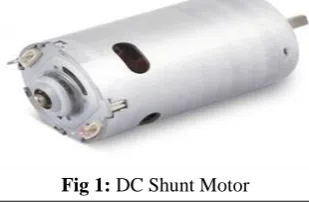
DC Shunt motor, Servomotor, Super-capacitor, AVR, Micro-controller, Motor Driver IC.I.
Introduction
Since last few years people mobility has increased in urban areas, implying the necessity of rapid transit improvement in terms of passenger capacity and number of journey than metro is the best option. The charging of this unit is done by using electric supply, and this charging port is positioned on each and every metro station to make available supply to super-capacitor for its charging. The main benefit of super-capacitor is, it take less charging time. We also install ultra sonic sensors in our metro system in order to avoid accident and maintain the safety of passengers and vehicle. These sensors are to be found in-front of the train. These sensors be full of transmitter and receiver. When metro train engages in the braking action, the super-capacitor unit converts kinetic energy- energy that is lost in friction braking system into stored electrical energy. Unlike batteries, super capacitor rapidly charge and discharge, enabling them to capture and store energy during braking. Battery based system have limited ability to absorb energy in few second required to stop metro train.
II.
Theory And Modelling
In INDIA the metros are running using overhead transmission lines on 25000 volt AC. These overhead lines are having several disadvantages such as the maintenance of overhead lines is very difficult, the complete system shut down during maintenance of overhead lines and during fault condition. This creates a great impact on whole system, hence to overcome this disadvantage, this project finds a replacement of super capacitors for the overhead lines. This replacement is of great significance it helps to save a great amount of energy.
The Paper has presented an overview of the application of super-capacitor based energy storage system in electrical rail system. For demo practical hardware presentation, number of components is being used.
A. DC Shunt Motor
The ability of the DC shunt motor to maintain a set rpm at high speed when the load changes are due to the characteristic of the shunt field and armature. Since the armature begins to produce back EMF as soon as it starts to rotate, it will use the back EMF to maintain its rpm at high speed. If the load increases slightly and causes the armature shaft to slow down, less back EMF will be produced. This will allow the difference between the back EMF and applied voltage to become larger, which will cause more current to flow. The extra current provides the motor with the extra torque required to regain its rpm when this load is increased slightly.
B. Servomotor
Fig 2: Servomotor
The Servo Motor basically consists of a DC Motor, a Gear system, a position sensor and a control circuit. The DC motors get powered from a battery and run at high speed and low torque. The Gear and shaft assembly connected to the DC motors lower this speed into sufficient speed and higher torque. The position sensor senses the position of the shaft from its definite position and feeds the information to the control circuit. The control circuit accordingly decodes the signals from the position sensor and compares the actual position of the motors with the desired position and accordingly controls the direction of rotation of the DC motor to get the required position. The Servo Motor generally requires DC supply of 4.8V to 6V.
C. Super-capacitor
Fig 2: Super-Capacitor
Fig 3: Individual Ultra Capacitor Cell Diagram The construction of super capacitor is similar to the construction of electrolytic capacitors in that they consist of two foil electrodes, an electrolyte and a foil separator. The separator is sandwiched between the electrodes and the foil is rolled or folded into a shape, usually cylindrical or rectangular. This folded form is placed into a housing, impregnated with electrolyte and hermetically sealed. The electrolyte used in the construction of super capacitors as well as the electrodes, are different from those used in ordinary electrolytic capacitors.
In order to store electrical charge, a super capacitor uses porous materials as separators in order to store ions in those pores at an atomic level. The most commonly used material in modern super capacitors is activated charcoal. The fact that carbon is not a good insulator results in a maximum operating voltage limited to under 3 V.
III.
Control Circuit
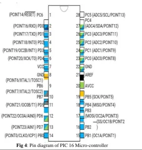
A. Micro-controllerProgrammable microcontrollers contain general purpose input/output pins. The number of these pins varies depending on the microcontroller. They can be configured to an input or an output state by software. When configured to an input state, these pins can be used to read external signals or sensors. When they are configured to the output state, they can drive external devices like LED displays and motors. Mixed signal microcontrollers are common, integrating analog components needed to control non-digital electronic systems. In the context of the internet of things, microcontrollers are an economical and popular means of data collection, sensing and actuating the physical world as edge devices.
B. Infrared sensor (IR) and ultrasonic sensor (Obstacle sensor)
Fig 5: IR sensor
The emitter is simply an IR LED (Light Emitting Diode) and the detector is simply an IR photodiode which is sensitive to IR light of the same wavelength as that emitted by the IR LED. When IR light falls on the photodiode, The resistances and these output voltages, change in proportion to the magnitude of the IR light received.An infrared sensor is an electronic instrument that is used to sense certain characteristics of its surroundings. It does this by either emitting or detecting infrared radiation. Infrared sensors are also capable of measuring the heat being emitted by an object and detecting motion.infrared technology is found not just in industry, but also in every-day life. Televisions, for example, use an infrared detector to interpret the signals sent from a remote control. Passive Infrared sensors are used for motion detection systems, and LDR sensors are used for outdoor lighting systems
FIG 6: Ultrasonic sensor
Ultrasound is reliable in any lighting environment and can be used inside or outside. Ultrasonic sensors can handle collision avoidance for a robot, and being moved often, as long as it isn’t too fast. Ultrasonic are so widely used, they can be reliably implemented in grain bin sensing applications, water level sensing, drone applications and sensing cars at your local drive-thru restaurant or bank. Ultrasonic rangefinders are commonly used as devices to detect a collision.
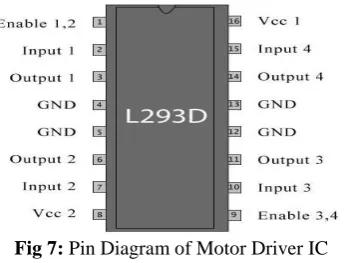
C. Motor Driver IC
The L293D IC receives signals from the microprocessor and transmits the relative signal to the motors. It has two voltage pins, one of which is used to draw current for the working of the L293D and the other is used to apply voltage to the motors. The L293D switches it output signal according to the input received from the microprocessor.
IV.
Working
This super-capacitor unit is placed on train so that it directly transmits its power to the motor of the metro train. This super-capacitor is acts like a battery hence, battery also gets discharge by giving its power to full filling the need of some system operation. Just like that super-capacitor also get discharge after some period of time by supplying continuous power to motor, so it is necessary to charge this capacitor unit. The charging of super-capacitor bank is done on metro station means we will provide charging point on each and every station and the charging is done via means of pantograph which is situated at top of metro train. Pantograph is operated with the help of servo motor. A servo motor is electrical device which can push or rotate an object with great precision. If you want to rotate an object with at some specific angles or distance you can use servo. It is just a simple motor which can run on servo mechanisms. If motor works o dc then it is called DC servo motor and when it work on AC then it is called as AC servo motor.
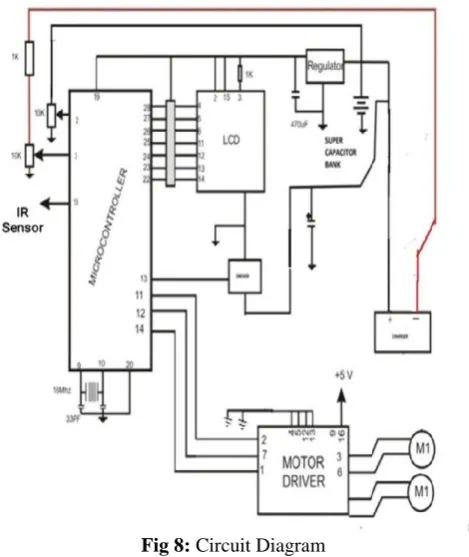
Fig 8: Circuit Diagram
We can get very high torque servo motor in a small and light package. Does these features they are being use in toy car, RC helicopter and planes, robotics etc. We use line follower instead of rail route. Our metro train will run with the help of line follower .line follower is the autonomous train which follower either black line in white area. Train must be able to detect particular line and keep following it.
Above fig shows the circuit diagram of research project. Consist of microcontroller which is important part of this project it operates whole system of metro train. It contains of motor which is operated through microcontroller. From supply it comes 230volts ac but our devices are work on12 volt so we have to step down this voltage to 12 volt for operating whole project. There are two DC motor connected across each other. This motor will moves in both the direction forward as well as in reverse direction. We provide logic 0 or 1 acrossthe input pin for rotating motor. The operation of the motor explains below. Let’s consider a motor connected with output pin for rotating a motor logic 1 & logic 0.
Logic 1 & logic 0 = Clockwise direction Logic 0 & logic1 = Anticlockwise direction Logic 0 & logic 0 = No rotation
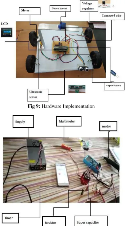
Fig 9: Hardware Implementation
Fig 10: Charging and discharging processing Unit
V.
Result
Super-capacitor charge very fast and discharging time of super-capacitor is slow. Super-capacitor charging and discharging result give to following are:-
CALCULATION:-
The energy consuming components of the project are the two 12v dc motors. These motors are used to run the metro train. Another energy consuming component is the servomotor its rating is 5V hence its energy consumption is negligible.
VI.
Conclusion
The use of on board of super capacitors unit represents a solution technically effective and feasible for the reduction of power peak demand up to 50%, with consequence reduction of line drop voltage up to 1% and recovering energy on board during braking operations up to 30%. These improvements can lead to reduction of power demand on the infrastructure allowing an increase of the distance between substations for the planned new lines and the reduction of time intervals between consecutive trains in existing lines. Moreover the onboard energy storage allows an autonomous operation, i.e. moving the vehicle to the next station in case of lost of power. Another benefit could be the additional power of super capacitors used to boost the vehicle when the catenary power is limited. However, the use of onboard super capacitors involves also disadvantages like increases of train mass by approximately 10% and the necessity of additional space to accommodate the energy storage containers.
Acknowledgment
There was article published in November 2017 conference which is the “6th International Conference on Renewable Energy Research and Application” by “Mahdiyehkhodaparastan” and “Ahmed Mohamed” on“Super-capacitor for Electric Rail Transit System”
The Paper has presented an overview of the application of super capacitor based energy storage system in electrical rail system. Super capacitor (SC) is an energy storage technology that is rapidly developing, and being industrial application. Server electric rail transportation system currently use super capacitor for voltage enhancement and improving recuperation of regenerative braking energy . In this paper a comprehensive review of the various aspects related to super capacitor applied in electric rail system, such as theirs design sizing and modeling, has been presented.
References
[1] Adinolfi, R. Lamedica, C. Modesto, A. Prudenzi, S. Vimercati, “Experimental assessment of energy saving due to trains regenerative braking in an electrified subway line”, IEEE Trans. Power Delivery, vol. 13, issue 4, pp. 1536-1542, 1998.
[2] Mellitt, Z. S. Mouneimne, C. J. Goodman, “Simulation study of DC transit systems with inverting substations”, IEE Proc. Electric Power Application, vol. 131, issue 2, pp. 38-50, 1984.
[3] Chan-Heung Park, Su-Jin Jang, Byoung-Kuk Lee, ChungYuen Won, Han-Min Lee, “Design and control algorithm research of active regenerative bidirectional DC/DC converter used in electric railway”, ICPE’07 7th International Conference on Power Electronics, pp. 790-794, 22-26 Oct. 2007.
[4] Morita, T. Konisihi, S. Hase, Y. Nakamichi, H. Nara, T. Uemura, “Verification tests of electric double layer capacitors for static energy storage system in DC electrified Railway”, Proc. of IEEE International Conf. of Power Electronics SPEEDAM 2008, Ischia, Italy, pp. 1017-1022, June 2008.
[5] Y. Taguchi, M. Ogasa, H. Hata, H. Ijima, S. Ohtsuyama, T. Funaki, “Simulation results of novel energy storage equipment series- connected to the traction inverter”, European Conference on Power Electronics and Applications, pp. 1-9, 2-5 Sept. 2007.. [6] S. D’Arco, D. Iannuzzi, E. Pagano, P. Tricoli, “Energy management of electric road vehicles equipped with supercaps”, Conf. Rec.
of Innovative Power Trains Systems, VDI-Berichte 1852, pp. 507-519, 2004