Energy Efficient BLDC Drive with Constant
Torque using C-Dump Technology
M. Bharani Lakshmi A. Marimuthu
Assistant Professor AssociateProfessor
Department of Electrical & Electronics Engineering Department of Electrical & Electronics Engineering K.L.N College of Engineering K.L.N College of Engineering
S. Priyanka M. Pon Sarumathi
UG Student UG Student
Department of Electrical & Electronics Engineering Department of Electrical & Electronics Engineering K.L.N College of Engineering K.L.N College of Engineering
M. Parameswari
UG Student
Department of Electrical & Electronics Engineering K.L.N College of Engineering
Abstract
Increasing utility load for a particular Permanent Magnet Brushless DC Motor (PMBLDC), it suffers from getting more input from the source so certain considerations should be made to avoid this. One among the consideration is about the design of the Motor. It should be modified in a form having better efficiency and constant Torque so that it can reducing the input consumption resulting in energy saving. PMBLDC drives are becoming widely used in various consumers and industrial applications such as Servo motor drives, Home Appliances, Computer Peripherals and Automotive Applications because of its silent operation, compact size, Reliability and Low Maintenance. In our paper these features can be enhanced by using energy recovery scheme. The main aim is to design a Simulation model of Permanent Magnet Brushless Dc motor and to increase it usage. To promote energy efficient, we employ C-dump technology. The principle behind this technology is that the capacitor is added to the circuit to store the demagnetized energy of the stator windings. Also the stator winding is excited in a way to produce constant torque. Hence the PMBLDC drive with increased efficiency and constant torque achieves its greater usage.
Keywords: C-Dump Technology, PMBLDC Motor, Simulink Model, Transfer Function
________________________________________________________________________________________________________
I. INTRODUCTION
PMBLDC motor has a wide range of applications in many field such as Industries, Medical, and Domestic as well as in Transport due to its inherent properties. These properties are enhanced by using C-dump Technology in PMBLDC Motor. The Energy Extracted from the Turn off Phase of the PMBLDC motor is recovered by C-Dump Converter [1]. By using this technique, we use the step-down chopper available in this C-dump method. This reduces the fear of high voltage. This makes the drive more suitable for use. The PMBLDC motor stator winding are energized by semiconductor switches connected across it.The sequence of Energization is controlled by the triggering angle of the semiconductor switches connected with stator winding. During Turn-off phase of the particular phase winding the charge stored in that winding is free-wheeled through the diode which connected across the winding and the recovered charge that is required which is stored in capacitor makes energy recover.
II. PRINCIPLE AND WORKING
Fig. 1: C-dump convertor for BLDC machine
Fig (1) illustrates the C-dump convertor for BLDC machine. It consists of thyristors, feedback diodes and charge storing capacitor. When the supply is ON, the switch T1 gets turn ON and hence the phase winding A gets excited. According to the rotor position sensed by the hall sensor the phase windings are excited so as to produce the rated speed, constant torque etc.[3]., Phase A, Phase B and phase C gets excited simultaneously according to the position of rotor The converter employs 120 degree conduction mode having switching duration of about 60 degrees. The conduction sequence are as T1,T2,T3,T4,T5 and T6.The input quasi sinusoidal is obtained using the converter circuit so that the Trapezoidal back Emf is generated. The switching operation also brings constant torque and so torque control is also possible. The drive operation is in two modes one as Turn ON phase of the winding and another one is Turn OFF phase of the winding[4]. When phase a winding get energized the power flow from the supply through the phase A and to the load. At this instant the phase B and phase C are also excited according to rotor position also carries the load [5]. At the turn OFF duration, the magnetized energy which is stored in that winding is collected or feedback through the diodes to the capacitor and hence supplied to the source. This reduces the energy consumption by the motor and thereby increases the Efficiency.
IV. SIMULATION AND WORKING
The mathematical model of PMBLDC motor is obtained by using Transfer function and State space model [6]. The equations which evolve in MATLAB simulation diagram is as follows
Supply Voltage
V = IR + L(dI/dT) + E (1)
Taking Transfer Function
(2)
(3)
Emf equations is represented as
(4) Where,
i represents number of phases (i=a, b, c)
fi(q) Represents function of rotor position on which the stator gets excited.
Torque equation is given by
(5)
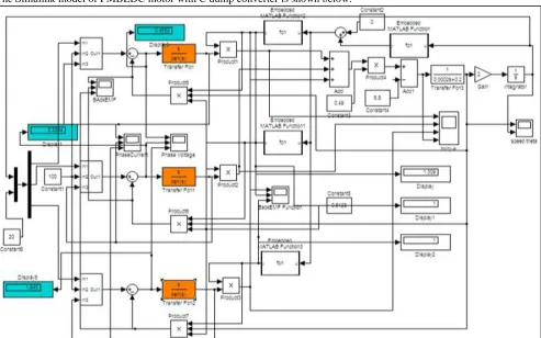
Fig. 2: Simulink Model of PMBLDC motor without C dump converter
The Simulink model of PMBLDC motor with C dump converter is shown below.
Load Torque (Te) =6.8Nm
VI. RESULTS
The graphical results showing phase voltage, phase current, torque, speed, and back emf without Capacitor dumping is shown below.
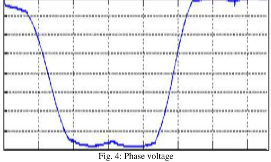
Fig. 4: Phase voltage
The Fig 4 shows the per phase voltage with respect to time.
Fig. 5: Phase current
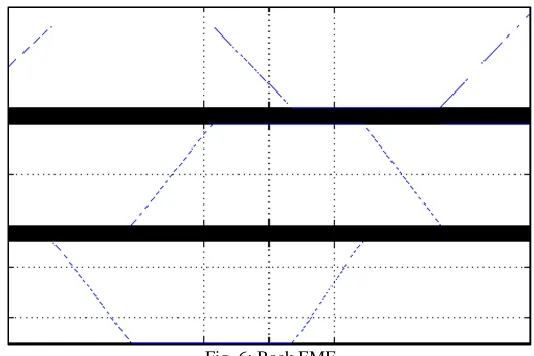
Fig. 6: Back EMF
The Fig 6 shows back emf of three phases with respect to time.
Fig. 7: Speed and Rotor Position
The Fig 7 shows the speed and rotor position with respect to time.
Fig. 8: Electromagnetic Torque
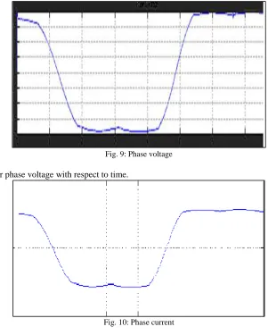
Fig. 9: Phase voltage
The Fig 9 shows the per phase voltage with respect to time.
Fig. 10: Phase current
The Fig 10 shows the per phase current with respect to time.
Fig. 11: Back EMF
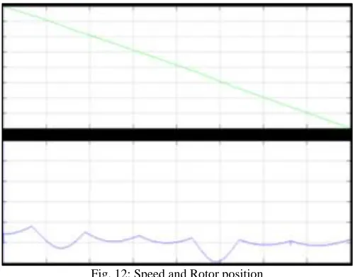
Fig. 12: Speed and Rotor position
The Fig 12 shows the speed and rotor position with respect to time.
Fig. 13: Electromagnetic Torque
The Fig 13 shows the electromagnetic torque with respect to time.
The result is clearly shown using display block in simulation diagram which is shown as simulation results tabulation as follows Table – 1
Simulation results
Without capacitor(v) With capacitor(v)
Phase A Voltage 0.4643 0.4652
Phase B Voltage 0.3388 0.3394
Phase C Voltage 1.846 1.846
Emf A 1.309 1.309
Emf B 1 1
Emf C 1 1
REFERENCES
[1] R.Krishnan,”Electrical Motor Drives Modelling Analysis and Control”, refer 9.10.7.2 Maged N.F.Nashed “Four Quadrant Control of Cdump Converter fed PMBDC Motor Drive System”, IFAC Symposium on Large Scale Complex Systems, 2013.
[2] Souvik Ganguli”Analysis of a Cdump Converter for Switched Reluctance Drive Using PSPICE”, International Journal of Advanced Engineering Technology E-ISSN 0976-3945.
[3] Parvatham Paramesh Venkateswarlu and Sunitha”Performance Analysis of C-dump Converter for BLDC Machine Application in a flywheel Energy Storage System. An International Journal (EEIEJ), Vol.1, No.1, February 2014.
[4] P.S.Bimbhra,”Generalized Theory of Electrical Machines”, Khanna publishers, Delhi, India, 2001, pp.93-98. [5] G.K.Dubey,”Power Semiconductor Controlled Drives”, Englewood, Cliffs, N.J.Prentice Hall, 1989.
[6] A.Hava, V.Blasko and T.A.Lipo,”A Modified C-dump Convertor for Variable Reluctance Machines”, IEEE transactions on Power Electronics &Industry Applications, Volume: 28, No: 5, pp.1017-1022, 1992.