Extension of the System Development Life Cycle
(SDLC) for the Analysis of Complex Problems
Shanelle Harris LeeRoy Bronner, Ph. D, P.E.
Doctoral Candidate Associate Professor
Department of Industrial Engineering & Systems Engineering
Department of Industrial Engineering & Systems Engineering
Morgan State University Morgan State University
Abstract
The current System Development Life Cycle (SDLC) is used for large system and software development projects. SDLC is a methodology that describes the stages of analysis in a project from initiation to completion. However, with 21st century problems increasing, the boundaries have been reached and an improved approach is needed. This research addresses the complexities of the development of a Modified System Development Life Cycle (MSDLC). This modification extends the capabilities of the SDLC. The MSDCL includes Joint Application Development (JAD) sessions, continuous user involvement, and intermediate documentation of analysis to expand the SDLC capabilities. Major additions are incorporated into the cost saving system analysis phase. To expand on the cost savings found in the system analysis phase, a three-phase modeling and analysis process has been defined: Object-Oriented, Z language, and Alloy to provide a more complete analysis and validation procedure to improve problem solutions.
Keywords: Alloy, Object-Oriented Analysis, System Analysis, System Development Life Cycle, Z language
________________________________________________________________________________________________________
I. INTRODUCTION
Life Cycle Variation
The SDLC has not been static since 1960s. It has evolved, however with its evolution there are still gaps and need for improvement with complex systems. A brief description of the evolution will follow.
The SDLC that was developed in the 1960s was designed to help with large business systems. The systems were heavily based on data processing and mathematical routines [1]. The Waterfall model was the first SDLC method employing a linear and sequential phase method. The Waterfall model has a set of defined outputs or deliverables that must be produced before the phase could be deemed complete; no iteration was permitted on previous phases [2,3]. However, there is extensive written documentation, reviews, and signoffs before the next phase can begin [4,5]. There is an emphasis on “planning, time schedules, target dates, budgets, and implementation of an entire system at one time” [4].
Winston Royce documented the waterfall method in 1970; however, Royce did not mention waterfall in the article. It was meant to represent a flawed non-working model [6,7]. This leads to the many failures, a need for a better methodology, greater flexibility, and quicker results [8]. The next phase of SDLC development was the Iterative methods. The Iterative methods were introduced in the late 1970s. According to Lehman (1969) and Larman and Basili (2003) “the basic approach recognizes the futility of separating design, evaluation, and documentation processes in software-system design. The design process is structured by an expanding model seeded by a formal definition of the system, which provides a first, executable, functional model. It is tested and further expanded through a sequence of models that develop an increasing amount of function and an increasing amount of detail as to how that function is to be executed. Ultimately, the model becomes the system” [9,10]
Some popular forms of the Iterative approach are Prototyping, Incremental, and Spiral. The Prototype approach does allow for multiple iterations; however, its downfall occurs with the multiple iterations. It is assumed that the prototypes will be discarded and unsuccessful. This assumption is partially due to knowing the requirements can change drastically in the next iteration [5]. The Incremental approach is mix of the Waterfall and Prototyping approaches. The Incremental approach develops, implements, and tests a system incrementally until the product is completed [5,11]. This also is similar to multiple small waterfalls.
The Spiral approach also expands on the Waterfall and Prototyping models using smaller segments during the development process but maintains a focus on risk assessment [4,5,8,12]. Building upon the Waterfall and Prototyping models, the Spiral approach can reduce issues of iteration but requires expertise in risk identification, risk projection, risk assessment, and risk management. The associated cost of the risk analysis makes this approach not ideal for small systems. The risk analysis cost would be greater than the entire system cost [4,11,12].
the cycle [13]. Agile is heavily dependent on user feedback and the phases of the life cycle are revisited continuously [14,15]. The iterative nature of the process allows requirements to be implemented later or upon the availability of technologies as a solution [14,16]. Ideally, the approach will produce a product every three to four weeks because it is divided into small increments instead of one large model allowing the system to be customizable [13,14].
Limitations
All the SDLC methodologies have limitations. The waterfall model was found to have limitations in manageability due to lack of iteration, inconsistent requirements, instability, gap between users and developers, failure to meet user needs, overly conservative system designs, difficulty responding to changes, user dissatisfaction, lack of documentation, and the user not obtaining the final product until completion [2,34,5,6,11,17]. The inability to return to the previous phases can cause complications as the waterfall approach continues.
With the limitations of the Waterfall Approach, the response was the creation of new variations of the SDLC. The SDLC not only has multiple methods but has a failure rate as high as 80% [18]. Failure is greatly based on scope creep, unclear requirements, and lack of methodology [17,18,19,20]. References 20 and 21 explains that 60% of defects are introduced in the requirements and design phases. This is referred to as the 60% rule. Unclear requirements can cause multiple problems further down the life cycle. Baltzan and Phillips (2010) reveal that the most common reason systems fail is due to missing or incorrectly gathered requirements in the analysis phase. Requirements are the driver for the system, incorrectly or inaccurately defining the requirements is a poor foundation for a program. This also coincides with the least expensive phase to adjust.
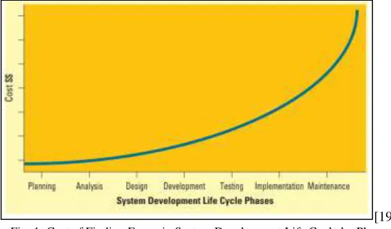
[19] Fig. 1: Cost of Finding Errors in System Development Life Cycle by Phase
Figure 1 displays an exponential cost growth as errors are found later in the SDLC phases. Bunting (2012) found that the largest portion of cost over-runs (32%) was due to missing or incorrect requirements as seen in Figure 2. This finding is based on industry metrics, collected data, and project experience [22].
[22] Fig. 2: Key Reasons for High Estimates or Cost Over-runs
The issues resulting from unclear requirements have a foundation in lack of communication and lack of user involvement. Errors are introduced into the development due to ambiguity, assumptions, and flawed human communication. This occurs by a change of functionality being introduced. The test-fix-test approach is then used to find errors. However, with each addition, there is an increasing risk that the purpose will be lost. Avison and Fitzgerald (2003) have discovered that programmers typically developed systems without the user. This development style leads to poor project management and failure to meet the user’s requirements. The developer may encounter a user with the “I know it when I see it” (IKIWISI) syndrome, typically found in new systems [23]. This syndrome enforces the need for continual user communication. Boehm and Hansen (2001) and Saunders (2014) have found that omitting the user involvement between each phase leads to risks not being detected and system failure.
MSLDC
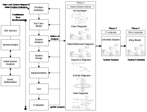
The National Academy of Engineering (2008) states that as the population increases “the problem of sustaining civilization’s continuing advancement, while still improving the quality of life, looms more immediately.” Twenty-first century researchers, engineers, and scientists are facing problems characterized by unstable elements, large of amounts of data, short timelines for solutions, multiple discipline areas, etc. [24,25]. In February 2008, a group of engineers and scientists developed a list of engineering challenges of the 21st century, including securing cyberspace, restoring and improving urban infrastructure, advancing health informatics, reverse-engineering the brain, and preventing nuclear terrorist attacks [24]. This list will only continue to grow. The current System Development Life Cycle was developed and used for large engineering and software projects. The purpose of this research is to develop a validated model and analysis process to provide solutions with fewer inaccuracies through modifications to the SDLC system analysis phase with the use of a three-phased system analysis process, JAD sessions, continuous user involvement, and intermediate artifacts of analysis. The extended analysis phase integrates object-oriented analysis, Z language, and Alloy modeling. The modified system development life cycle (MSDLC), in Figure 3, will provide a system analysis process that can be implemented to solve complex, dynamic problems and provide intermediate visual solutions. The MSDLC will specifically address scope creep, lack of defined requirements, final solution preview, and lack of user involvement to expedite finding problems. The proposed MSDLC methodology in Figure 3 shows all added elements and expanded analysis phase.
User Involvement
The MSDLC has implemented a constant interaction with the user. In the past, the users’ role was relatively passive in the system development, leaving the IT department with the sole responsibility of systems development [26]. The modification intentionally involves users in each step of the MSDLC.
User involvement in entering and exiting each step minimizes the risk for scope creep and unclear requirements which leads to a product that is likely to meet users’ needs. The user involvement also allows the user to have a sense of ownership of the project [26]. The implementation of user involved cannot be overemphasized.
Joint Application Development (JAD) Session
Traditionally the SDLC begins with a problem statement. However, in the MSDLC before a problem statement is solidified a Joint Application Development (JAD) session will be held. A JAD session is a meeting that is held over a period of days, allowing all key parties to meet to discuss expectations for the project with the goal of accelerating the development process, increasing productivity and quality, and building developer-client relationships [26,27].
The purpose of this meeting is to start developing ideas through phases. JAD sessions have a five-phase process: project definition, research, preparation, the session, and the final document [28]. From the session, participants/team members will construct an outline of the project definition [28]. An initial high-level system diagram (HLSD), a narrative of the initial problem definition, will result from the discussion and possible problem solutions. The HLSD is a visual depicting the problem. The visual defines the problem and the interactions between the users and any entity. The HLSD provides a clear and quick understanding of the problem.
Because of the JAD session and HLSD, participating parties have a clear initial problem definition and a path forward. The committed group now has a system design process with formulated scope [27,28].
System Analysis Phase 1: Object-Oriented Analysis (OOA)
The MSDLC is a combination of modeling processes: OOA, Z language and Alloy are used to adjust to the complex and dynamic systems. The first phase will be an implementation of Object Oriented Analysis (OOA). This methodology is used to define and analyze the problem. In further defining the problem, the problem vocabulary is developed. The vocabulary includes the objects, attributes, and behaviors of the model. The objects, attributes, and behaviors are found through analysis of the use case scenario. Use case scenarios are developed through the requirements elicited from the problem definition derived from the JAD session. The requirements will state what a system is to do, not how the system should implement the tasks [29]. The use case development identifies and defines requirements by capturing scenarios of all possible functions (events) that produce a measurable result from the user’s point of view [29,30].
By utilizing the use case process, attributes and behaviors are defined. The attributes are characteristics of an object such as name, address, or age. Behaviors are functions that the object can perform such as shop, sort, and wash laundry. This information is documented in class, object, rationale, sequence, activity, and/or state diagrams [30]. The diagrams are produced using the Unified Modeling Language (UML). The Object Management Group (OMG) (2015) states that “he UML is a graphical language for visualizing, specifying, constructing, and documenting the artifacts of a software-intensive system. The UML offers a standard way to write a system's blueprints, including conceptual things such as business processes and system functions as well as concrete things such as programming language statements, database schemas, and reusable software components” [31].
System Analysis Phase 2: Z language
After OOA is performed, a highly expressive formal mathematical notation for specifying and capturing the behavior of systems, Z language, will be implemented [32]. Z language is based on set theory and a typed first-order predicate logic model. “Typed” means that variables in Z cannot be defined without knowing the range of values that it can hold and, once the variable is declared, its type cannot change [32]. Shen (2002) simply states that set theory deals with sets, their operations, relationships, and statements about these relations [33]. Gries and Schneider (1993) state that “predicate calculus is an extension of the propositional logic that allows the use of variables of types other than Boolean [34]. This extension leads to logic with enhanced expressive and deductive power”. Predicate calculus “usually consists of inputs, outputs, and changes to the state of the system; these relational states will be described by a predicate relating and constraining these values” [35].
Z is predominantly used for specifying software because the required result is an error-free computer program using representational abstraction, procedural abstraction, and the structure of the schema [28,36]. Representational abstraction uses high-level mathematical data types in a way without knowing how it will be implemented. Abstraction is the ability to describe what can be done without stating how it is done [32]. The use of abstraction directly links to the schema structure since it is based on declaratives. The schema structure is a means of organizing its notation around the definition of the problem entities being analyzed. The schema structure has two sections, declarative and criterion.
System Analysis Phase 3: Alloy Language
The last phase of the modified system analysis phase is Alloy modeling. A process from Massachusetts Institute of Technology (MIT) that evaluates Z notation. Alloy find the logical paths. Phase 3 is the Alloy modeling and system evaluation part of the MSDLC methodology. Alloy is a modeling language for expressing complex structural constraints and behavior about systems by employing a first-order logic, Z language [37,38]. A unique characteristic of Alloy is that it analyzes systems with configurations that are undetermined. Alloy’s ability to conduct incremental analysis in time and space allows for the exploration of different designs starting from a small model, which is then scaled up [37]. Alloy can analyze the model at every step. The purpose of converting Z to Alloy is to use Alloy to find errors in the logic of Z. Alloy makes it possible to check the criteria of the specification to assure correct execution of the solution [37].
Alloy attacks the notion of software or system abstraction in a problem solution from a unique point of view assuming the problem solution does not work well. Therefore, Alloy addresses solving complex problems with three elements; logic, language, and analysis [38]. Logic provides the building blocks for the language in terms of relations and operations (Jackson, 2002). Having a language adds syntax and structure to the logic descriptions. The analysis phase is not a solution through a theorem but the use of an instant process. This analysis approach is a form of constraint solving. A process of simulation is used to find instances of states or executions that satisfy a given property [38]. To check the model, a counterexample is found that violates a given property.
II. CONCLUSION
Analysis and solution of complex systems pose a great problem for the 21st century. The SDLC is inadequate for addressing many types of complex system problems of the 21st century. The use of integrated methodologies provides a solution for solving certain of these problems. New research methodologies, new tools and innovative approaches are needed for problem solving in the future. Also, modeling and evaluation must continue to advance from instance evaluation to a proof of solutions. A more rigorous validation of solutions will make performance of production systems more stable and error free. The explained process will be evaluated to determine the potential for error free approaches.
REFERENCES
[1] Elliott, G. (2004). Global Business Information Technology: An Integrated System Approach. Pearson Addison Wesley.
[2] Avison, D. E., & Fitzgerald, G. (2003). Where Now for Development Methodologies? Communications of the ACM, 46(1), 79-82.
[3] Rouse, M. (2007, February). Waterfall Model. Retrieved from Tech Target: http://searchsoftwarequality.techtarget.com/definition/waterfall-model [4] Davis, A. (2014). A Comparative Study of Prescriptive Process Models. VISTAS, 3(1), 94-100.
[5] Council, W. I. (2014). Chapter 2 System Development Life Cycle Methodology. Retrieved from Western India Regional Council: https://www.wirc-icai.org/material/2-System-Development-Life-Cycle-Methodology.pdf
[6] Curtis, B., Krasner, H., & Iscoe, N. (1988, November). A Field Study of the Software Design Process for Large Systems. pp. 1278-1287.
[7] Ragunath, P., Belmourougan, S., Davachelvan, P., Kayalvizhi, S., & Ravimohan, R. (2010). Evolving A New Model (SDLC Model-2010) For Software Develpment Life Cycle (SDLC). International Journal of Computer Science and Network Security, 10(1), 112-119.
[8] Khurana, G., & Gupta, S. (2012). STUDY & COMPARISON OF SOFTWARE DEVELOPMENT LIFE CYCLE MODELS. International Journal of Research in Engineering & Applied Sciences, 2(2), 1513-1521.
[9] Lehman, M. M. (1969). The Programming Process. Yorktown Heights: IBM Research.
[10] Larman, C., & Basili, V. R. (2003, June). Iterative and Incremental Development: A Brief History. IEEE Computer Society, pp. 1-11.
[11] Seema, & Malhotra, S. (2012). Analysis and tabular comparison of popular SDLC models. INTERNATIONAL JOURNAL OF ADVANCES IN COMPUTING AND INFORMATION TECHNOLOGY, 277-286.
[12] Ateeq, S., & Shuaib, M. (2014). COMPARISON OF VARIOUS SDLC MODELS. Global Journal of Multidisciplinary Studies, 3(11), 176-181.
[13] Sharma, S., Sarkar, D., & Gupta, D. (2012). Agile Processes and Methodologies: A Conceptual Study. International Journal on Computer Science and Engineering, 4(5), 892-898.
[14] Leau, Y. B., Loo, W. K., Tham, W. Y., & Tan, S. F. (2012). Software Development Life Cycle AGILE vs Traditional Approaches. IPCSIT, 37, 162-167. [15] Szalvay, V. (2004). An Introduction to Agile Software Development. Danube Technologies Inc.
[16] Cho, J. (2008). Issues and Challenges of Agile Software Development with SCRUM. Issues in Information System, IX(2), 188-195. [17] Saunders, C. (2014). Project Management. Retrieved from www.ou.edu/class/mis5003/mbapm.ppt
[18] Dorsey, P. (2000). Top 10 Reasons Why System Projects Fail. Retrieved from Dulcian: www.dulcian.com/articles/dorsey_top10reasonssystemsprojectsfail.pdf
[19] Baltzan, P., & Phillips, A. (2010). Appendix D. The Systems Development Life Cycle Basics. In M: Information Systems (pp. D1-D18). McGraw-Hill. [20] Jones, C. (2005, 04). Software Cost Estimating Methods for Large Projects. CROSSTALK The Journal of Defense Software Engineering, 8-12. Retrieved
from Jones, Capers. "Software Cost Estimating Methods for Large Projects." CrossTalk: April, 2005. www.stsc.hill.af.mil/crosstalk/2005/04/0504Jones.html [21] Jones, C. (1998). Estimating Software Cost. New York: McGraw Hill.
[22] Bunting, J. (2012, December 11). How We Reduce Costs Waste By Aligning Testing With The SDLC. (Optimation) Retrieved from Optimation: http://www.optimation.co.nz/our-work/blog/how-we-reduce-costs-and-waste-by-aligning-testing-with-the-sdlc
[23] Boehm, B., & Hansen, W. J. (2001, April). The Spiral Model as a Tool for Evolutionary Acquisition. Retrieved from Software Engineering Institute Carnegie Mellon University: http://www.sei.cmu.edu/pub/documents/00.reports/pdf/00sr008.pdf
[24] National Academy of Engineering. (2008, February). 14 grand challenges for engineering in the 21st century. Retrieved from NAE Grand Challenges for Engineering: http://www.engineeringchallenges.org/challenges.aspx
[25] Numrich, S. K., & Tolk, A. (2010). Challenges for human, social, cultural, and behavioral modeling. SCS M&S Magazine, 1-9. [26] Shelly, G. B., & Rosenblatt, H. J. (2012). System analysis and design 9th ed. Boston: Course Technology.
[27] Thierauf, R. J. (1999). Knowledge management systems for business. Westport: Quorum Books. [28] Wood, J., & Silver, D. (1995). Joint application development. New York: John Wiley & Sons, Inc. [29] Tsang, C. H., Lau, C. S., & Leung, Y. K. (2005). Object oriented technology 3rd ed. London: McGraw-Hill.
[31] Object Management Group. (2015, September). Unified modeling language™ (UML®) resource page. Retrieved from Object management group: http://www.uml.org/
[32] Spivey, J. (1989). The Z notation, a reference manual. New York: Prentice Hall.
[33] Shen, A., & Vereshchagin, N. (2002). Basic set theory. Providence: American Mathematical Society.
[34] Gries, D., & Schneider, F. B. (1993). Predicate Calculus. In D. Gries, & F. B. Schneider (Eds.), A logical approach to discrete math (pp. 157-177). New York: Springer-Verlag.
[35] Goldrei, D. (2005). Propositional and predicate calculus. London: Springer-Verlag. [36] Diller, A. (1994). Z: An introduction to formal methods. New York: John Wiley & Sons, Inc.
[37] Devlin, K. (1993). Naive set theory. In The joys of sets: Fundamentals of contemporary set theory (pp. 1-28). New York: Springer-Verlag. [38] Jackson, D. (2012). Software abstractions. Cambridge: The MIT Press.