Auto Smart Obstacle Detection
Prof. Trima P.Fernandes e Fizardo
Mr. Kakodkar Sujay GovindAssistant Professor (Guide) UG student
Department of Electronics and Telecommunication Department of Electronics and Telecommunication Engineering Engineering
Don Bosco College of Engineering Don Bosco College of Engineering
Miss Dessai BhavanaBholanath Mr. Fernandes Leo
UG Student UG Student
Department of Electronics and Telecommunication Department of Electronics and Telecommunication Engineering Engineering
Don Bosco College of Engineering Don Bosco College of Engineering
Mr. Fernandes Aliston Lucio
UG student
Department of Electronics and Telecommunication Engineering Don Bosco College of Engineering
Abstract
In order to help the visually challenged people, a study has been proposed to help visually impaired person to walk more confidently. The study hypothesizes a smart walking stick that alerts visually-impaired people where obstacles and pit ahead is concerned which will help them in walking without causing injury to them. In this system, ultrasonic sensors, ir sensor, headphone, Arduino controller, Micro sd card adapter are used. The overall aim of the device is to provide a convenient and safe method for the blind to overcome their difficulties in daily life.
Keywords: IR sensors; Ultrasonic sensors; Arduino; Obstacle detection; Micro SD card Adapter
________________________________________________________________________________________________________
I. INTRODUCTION
It is based on the use of new technology to improve visually impaired person's mobility. Our research focuses on obstacle detection and pit detection, in order to reduce navigation difficulties for visually impaired people. A visionless person commonly uses a walking/white cane or guide dogs for navigation. But guide dogs are still far from being affordable, around the price of anice car, and their average working time is limited, an averageof 7 years.[1][2]
In many applications, ultrasonic sensors are used because of its immunity to the environmental noise. Another reason why ultrasonic is popular is that the technology is relatively inexpensive, and also ultrasound emitters and detectors are small enough to be carried without the need for complex circuit as it is characterized by their reliability and outstanding versatility. Low power requirements, simple circuitry and portable features make infrared sensorsto find applications in electronic circuits. Micro SD card adapter allows to connect a micro-SD to microcontroller.
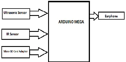
II. SYSTEM DESIGN
The proposed design for Auto-smart obstacle detection system distinctly consists of three units:
- Ultrasonic Sensor
- IR Sensor
- Micro SD card adapter
Features of Ultrasonic sensors
1) The device is extremely robust, making it suitable for even the toughest conditions. 2) The sensor surface cleans itself through vibration, making the sensor insensitive to dirt. 3) The physical principle—the propagation of sound—works, in practically any environment. 4) Ultrasonic sensors have proven their reliability and endurance in virtually all industrial sectors.[4]
Features of IR sensors
1) Low power consumption is a crucial feature of an IR sensor.
2) It can provide you with function guarantee for a particular period of time. 3) Can be used to measure brightness. Thus it is useful for tasks like line tracking. 4) IR sensor features long detection range.
Features of Micro SD adapter
1) The device helps to connect micro sd card to connect microcontroller. 2) Stores audio files in wmv format. [5]
III. MICROCONTROLLER
Arduino Mega is 5V 8-bit microcontroller. It has 54 digital input/output pins (of which 15 can be used as PWM outputs), 16 analog inputs, 4 UARTs (hardware serial ports), a 16 MHz crystal oscillator, a USB connection, a power jack, an ICSP header, and a reset button. It contains everything needed to support the microcontroller; simply connect it to a computer with a USB cable or power it with a AC-to-DC adapter or battery to get started.
Its DC Current per I/O Pin is 20 mA. Flash Memory is of 256 KB of which 8 KB used by bootloader. SRAM &EEPROM is 8 KB &4 KB respectively. It operates at Clock Speed of 16 MHz.[6]
Fig. 2: Arduino Mega 2560 Microcontroller
IV. WORKING PRINCIPLE OF AN ULTRASONIC SENSOR
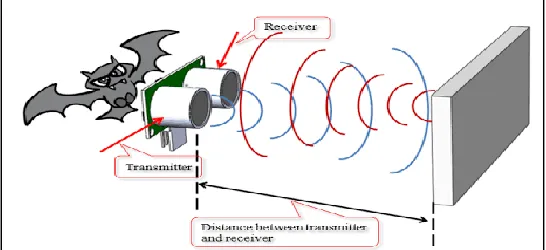
The ultrasonic sensor (also known as transceiver) works on same principle similar to radar or sonar which evaluates attributes of the target by interpreting the echoes from radio or sound waves respectively. Ittransmits sound waves of 40 KHz frequency is at a regular interval in the forward direction and receives sound reflected from an object. When ultrasonic waves are incident on an object, diffused reflection of the energy takes place over a wide solid angle which might be as high as 180 degrees. Thus some fraction of the incident energy is reflected back to the transducer in the form of echoes. If the object is very close to the sensor, the sound waves returns quickly, but if the object is far away from the sensor, the sound waves takes longer to return. But if objects are too far away from the sensor, the signal takes so long to come back (or is very weak when it comes back) that the receiver cannot detect it.[7]
The sensor uses the time it takes for the sound to come back from the object in front to determine the distance of an object.
Fig. 4: Distance measurement with Ultrasonic sensor
The distance to the object (L) can then be calculated through the speed of ultrasonic waves (v) in the medium by the relation, where, ‘t’ is the time taken by the wave to reach back to the sensor and ‘Ɵ’ is the angle between thehorizontal and the path taken as shown in the figure. If the object is in motion, instruments based on Doppler shift are used.The ultrasonic sensor can measure distances in centimetres and inches. It can measure from 0 to 2.5 meters, with a precision of 3 cm.
HCSR04 range sensor
HC-SR04 is a commonly used module for non-contact distance measurement for distances from 2cm to 400cm. It has 4 pins:
VCC – 5V, input power; TRIG – Trigger Input; ECHO – Echo Output; GND – Ground
Fig. 5: HCSR04 Ultrasonic sensor
A trigger signal is provided to TRIG input, a HIGH signal of at least 10μS duration. This enables the module to transmit eight 40KHz ultrasonic burst. If there is an obstacle in-front of the module, it will reflect those ultrasonic waves. If the signal comes back, the ECHO output of the module will be HIGH for duration of time taken for sending and receiving ultrasonic signals. The pulse width ranges from 150μS to 25mS depending upon the distance of the obstacle from the sensor and it will be about 38ms if there is no obstacle.[8]
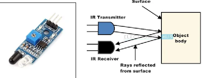
V. WORKING PRINCIPLE OF AN IR SENSOR
An infrared sensor is an electronic instrument which consists of an IR LED and an IR Photodiode; together they are called as Photo – Coupler or Opto – Coupler. Itis used to sense certain characteristics of its surroundings by either emitting and/or detecting infrared radiation.IR Sensors work by using a specific light sensor to detect a select light wavelength in the Infra-Red (IR) spectrum. By using an LED which produces light at the same wavelength as what the sensor is looking for, you can look at the intensity of the received light. When an object is close to the sensor, the light from the LED bounces off the object and into the light sensor. This results in a large jump in the intensity, which we already know can be detected using a threshold.Since the sensor works by looking for reflected light, it is possible to have a sensor that can return the value of the reflected light (brightness).[9][10]
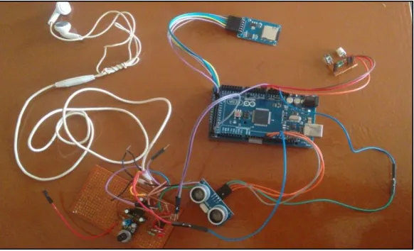
VI. OPERATION OF SYSTEM
Obstacle Detection
In this study we take the Ultrasonic sensor HCSR-04 and IR sensor which are controlled by Arduino mega. The figures 1&2 show the photographs of the sensors. Whenever an object or obstacles comes infront of the ultrasonic sensors, it will detect receiving signal and calculate the distance from the system. When a code is run and if an object lies below a threshold value (say 100cm) then the audio file stored in sd card will get played giving out voice command to blind person through earphone saying “OBSTACLE DETECTED”.
Fig. 8: Circuit proposed for Autosmart system
Now, ir sensor which is used to detect the pit ahead of the system is mounted onto system in such a way that it faces the surface. When code is run if there is pit in range of 150cm then ir value will be 1 and the pit will be detected. The system is programmed in such a way that after detection of pit, the audio file stored in sd card will get played through earphone giving a voice command “PIT AHEAD”.
Table - 1
Percentage error of HCSR04 Ultrasonic Sensor
Sr. No. Actual Distance (cm) Measured Distance (cm) Percentage error %
1 5 4.94 0.012
2 8 7.86 0.0175
3 10 9.98 0.002
4 13 13.19 0.015
5 15 14.82 0.012
6 18 18.2 0.011
7 20 20.03 0.0015
8 23 23.17 0.007
9 25 24.97 0.0012
10 28 27.87 0.0048
The experimental results for the distance measurement are shown in Table I. We observe that there is considerable error in the measured distance as compared to the actual distance. The %error column shows similar results. Since the error is very small, we can easily correct it while programing the code.
VII. CONCLUSION
The Ultrasonic and IRsensors were studied and the HCSR-04 ultrasonic sensor was selected, because its Accuracy, Resolution, Repeatability etc It will also be used for distance measurement of an obstacle. Also IR sensors will be used as pit detector in the system.
ACKNOWLEDGMENT
REFERENCES
[1] https://en.m.wikipedia.org/wiki/White_cane
[2] https://en.m.wikipedia.org/wiki/guide_dogs
[3] http://www.guidedogs.com/site/
[4] http://www.ab.com/en/epub/catalogs/12772/6543185/12041221/12041229/Ultrasonic-Advantages-and Disadvantages.html
[5] http://playground.arduino.cc/Learning/SDMMC
[6] https://www.arduino.cc/en/Main/ArduinoBoardMega2560
[7] http://www.engineersgarage.com/insight/how-ultrasonic-sensors-work
[8] www.micropik.com/PDF/HCSR04.pdf
[9] http://education.rec.ri.cmu.edu/content/electronics/boe/ir_sensor/1.html