ISSN (e): 2250-3021, ISSN (p): 2278-8719 Vol. 05, Issue 01 (January. 2015), ||V3|| PP 15-25
Laser Based Guidance System For Projectile
Gayathri. N
M.Tech Scholar, Laser and Electro Optical Engineering,Department of Information and Communication Engineering, College of Engineering,Anna University, Chennai, India
Abstract: - In this paper a hardware module of Laser based guidance system for projectile has been developed.The system uses a laser beam to guide a projectile to precisely hit a target. The guiding system generates a laser beam trajectory bygetting the range of target and velocity of projectile input manually.The guidance system in the projectile interpret the information contained in the laser beam and steers to track the beam to keep the projectile closer to the centre of the laser beam. Such guided projectiles can thus said to “ride” the beam to its target.The main aim is to design and develop a microcontroller based platform with two degrees of freedom(Azimuth and Elevation) with optical zoom facility to keep the diameter of the laser beam as a function of distance.In this project the line of sight will be on a static target. The trajectory of laser beam from the above system can be used as a guidance system for beam rider missiles. The project relates the azimuth, elevation and the optical zoom movement to generate the desired trajectory.
Keywords: -Drive Circuit for Motors, Laser, Lens and Microcontroller based platform, Stepper Motors
I. INTRODUCTION
Missiles differ from the rockets by virtue of a guidance system that steers them towards a predetermined target. Unguided rockets proved to be useful yet frequently inaccurate weapons when fired from aircraft during the World War II. Several warring nations, including the United States, German and Great Britain mated existing rocket technology with new radio-or-radar based guidance systems to create the world’s first guided missiles. The problems centered on the unreliability of the new radio-wave technologies. Dr.Theodore Maiman built the first laser (Light Amplification by Stimulated Emission of Radiation) at Hughes Research Laboratories in 1960. The military realized the potential applications for lasers almost as soon as their first beams cut through the air. The accuracy of these weapons earned them the well-known sobriquet of “smart weapons”. The laser guided missile has established itself as a key component in today’s high-tech military technology.
1.1 Need of Laser Guided Projectiles
Though many projectiles are developed, they don’t find accuracy as in reaching the target. Laser guided projectiles are invented due to the following advantages given below
(a) Pinpoint accuracy
(b) Ability to operate at night conditions of low or zero visibility (c) Simplicity, Reliability and Maintainability
(d) Resistance to jamming and other electronic countermeasures
Hence laser guided projectiles will be one of dangerous weapon in war field in present and will be the future. 1.2 Laser Guided Projectile
Laser guidance is a technique of guiding a missile or other projectile or vehicle to a target by means of a laser beam. Some laser guided systems utilize beam riding guidance, but most operate more similarly to semi-active radar homing (SARH). This technique is sometimes called SALH, for Semi-semi-active Laser Homing. With this technique, a laser is kept pointed at the target and the laser radiation bounces off the target and is scattered in all directions (this is known as “painting the target”, or “laser Painting”). The missile, bomb, etc.is launched or dropped somewhere near the target [3]. When it is close enough that some of the reflected laser energy from the target reaches it, a laser seeker detects which direction this energy is coming from and adjusts the projectile trajectory towards the source. As long as the projectile is in the general area and the laser is kept aimed at the target, the projectile should be guided accurately to the target.Laser Guidance is a technique of guiding a weapon such as a missile or a bomb to a target using a laser beam or spot. As known in the art there are two types (a) Internal Laser Target Designator and (b) External Target Designator.
LGW (e.g.: missile or projectile) is launched and at some point after launch is “gathered” by the radar or laser beam when it flies into it. From this stage onwards, the LGW attempt to keep itself within the beam, while the designator station keeps the beam pointed at the target [3]. The LGW, controlled by a laser or radar seeking guidance kit including photo detectors and a computer inside it, “rides” the beam to the target.
II. MODULE DESCRIPTION
A laser based guidance system for guiding a projectile to strike a moving or stationary target includes a laser source for providing a laser beam and a controller coupled to receive a position and a velocity of the target. The controller provides a control signal for pointing the laser beam on the tracked target.
Figure 1 Basic block diagram of laser based guidance system
Fig.1 shows the laser based guidance system for projectile. Here the target has been tracked to get the position and velocity. The position and velocity of the target has been fed manually or through laser range finder to the processor/controller. The processor/controller determines the specified distance of the moving target to generate a control command signal that is sent to the hardware setup or laser actuator for pointing the laser beam. Thus the resulting laser beam spot is positioned on the target.
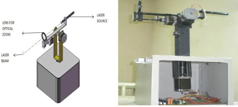
2.1 Experimental Setup
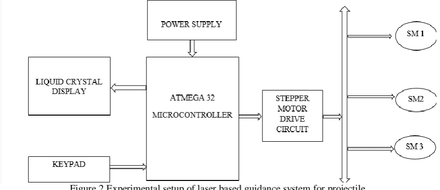
Fig 2 shows the experimental setup of laser based guidance system for projectile. The setup includes input system, controller and an output system. The input system includes LCD and KEYPAD and the output system is a hardware made of three stepper motors, laser and movable lens. Here the target range and azimuth angle have been fed manually through keypad setup.
Figure 2 Experimental setup of laser based guidance system for projectile
III. HARDWARE DESCRIPTION 3.1 Stepper Motor
A stepper motor is an electromechanical device which converts electrical pulses into discrete mechanical movements. Steppers can be moved to any desired position reliably by sending them the proper number of step pulses. The motor will be operated in an open loop (without feedback) system to reduce error.
3.2 Liquid Crystal Display
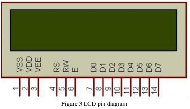
LCD is used in our project to display the range and angle input that has been fed manually. For simulation purposes, we can use LCD in a 4-bit mode. For that we require only four data lines to be connected to the four pins of ATMEGA 32 controller and three control signals to control the data flow and display. LCD pin diagram is shown below in fig 3
Figure 3 LCD pin diagram
3.2.1 Pin Description
The LCDs have a parallel interface, meaning that the microcontroller has to manipulate several interface pins at once to control the display. The interface consists of the following pins:
(a)RS Pin- A Register select(RS) pin that controls where in the LCD memory we are writing data to be. You can select either the data register, which holds what goes on the screen, or an instruction register, which is where the LCD’s controller looks for instruction on what to do next.
(b)R/W pin- A Read/Write(R/W) pin that enables reading or writing mode (c)Enable pin- the status of these eight data pins
(d) (D0-D7) pin – The status of these eight data pins (high or low) are the bits that we are writing to a register when we want write or the values we are reading when we need to read.
There is also a display contrast pin (VO), power supply(+5V and GND) and LED Backlight (Bklt+ and Bklt)pins that we can use to power the LCD, control the display contrast, and turn on and off the LED backlight, respectively. The process of controlling the display involves putting the data from the image of what we want to display into the data register then putting instructions in the instruction register. The Liquid Crystal Library simplifies this and there is no need to know the low level instructions.
3.2.2 Circuit Connection
To wire our LCD screen to AVR controller board, connect the following pins: (a)LCD RS pin to ATMEGA 32 controller pin 40
(b)LCD Enable pin to ATMEGA32 controller pin 39 (c)LCD D4 pin to ATMEGA32 controller pin 36 (d) LCD D5 pin to ATMEGA32 controller pin 35 (e)LCD D6 pin to ATMEGA32 controller pin 34 (f)LCD D7 pin to ATMEGA32 controller pin 33 (g)LCD R/W pin to GND
Additionally, wire a 10K pot to +5 V and GND, with its wiper (output) to LCD screens VO pin (pin 3)
3.3 Phone Keypad
Figure 4 shows the 3x4 pone keypad
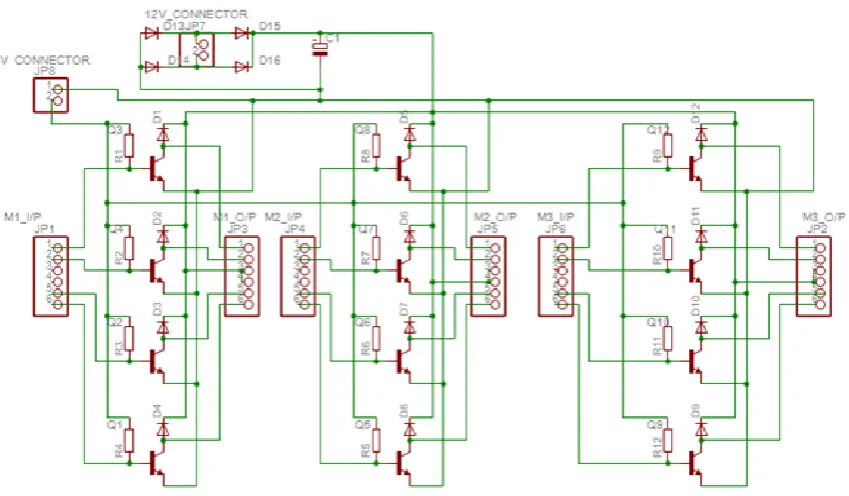
3.4 Stepper Motor Drive Circuit Board
The drive circuit board is made of TIP 122 Darlington transistor and diodes to generate the required pulses to drive all the three stepper motors. The basic details about TIP 122 transistor are given below. The stepper motor requires high current, to achieve current amplification we used TIP122, as shown in Fig. 5
Figure 6 Drive circuit of stepper motor
Like normal transistor it also consists of Base, Emitter and Collector. The TIP 122 comes with an extra metal that is used to connect external heat sink. Since TIP 122 can handle huge amount of current so it gets very hot and hence external heat sink is sometimes required. The diagram shows the configuration of how the base, collector and emitter are arranged in this transistor.
Two transistors are connected in the configuration shown with respect to each other. Pulses from AVR controller board comes to the base of the first transistor (Q1) and turns it ON. The base of the second transistor (Q2) is connected to the emitter of Q1 so that when Q1 is ON, Q2 is also ON. So when both the transistors are ON, current can flow from collector to emitter for both the transistors and the emitter current for both the transistors are added up in the end. This adding up of current, amplifies the current is given as input to the base of Q1, hence TIP 122 Darlington pair transistor works as current amplifiers.
3.5 AVR Controller Board
Fig. 7 shows the AVR development board with ATMEGA 32controller. In this project an AVR development board is used which works on 4 MHZ crystal frequency. This board is powered by 12 V supply. The programmer is connected to this board to dump the required code through ISP pin socket. The programmer here used is ATMEGA 128 circuit board.
3.6 ATMEGA 32 Controller
In our project, we needed a device that can make decisions to rotate all the three stepper motors in order to generate the required laser beam trajectory. This laser beam information will be interpreted by the projectile to hit target accurately. This can be achieved by ATMEGA 32 controller shown in fig. 8. This microcontroller is from the AVR ATMEL family with built in 32KB of memory.
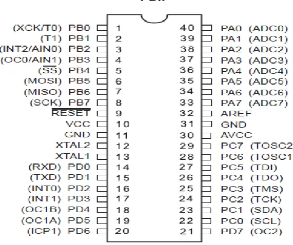
The ATMEGA 32 is a 40 pin with four ports for input and output. Fig. 3.6.2 shows the pin configuration of ATMEGA 32. From the figure it can be seen that pin 10 is reserved for +VCC which is 5 V and pin 11 is reserved for GND. For ATMEGA 32 to work properly a supply of 5 V is required.
Figure 8 ATMEGA 32 Pin configuration
For this project pin 14 to 20 of PORT D has been used as input that is keypad is connected to port D. Similarly PORT A pins 0 to 3 and PORT C 8 pins are used as outputs. Three stepper motors used for three movements are connected to these ports. The input fed can be displayed through LCD which is connected to PORT A
3.7 Laser and Lens
The laser used in this project paper is a simple laser pointer and the lens used is normal convex lens. The Laser specification and details are given below.
3.7.1Laser Source
Green Laser pointers appeared on the market are the most common type of DPSS lasers (also called DPSSFD for “diode pumped solid state frequency- doubled”) [6]. They are more complicated than standard red laser pointers, because laser diodes are not commonly available in this wavelength range. The green light is generated in an indirect process beginning with a high power (typically100-300mW) infrared AlGaAs laser diode operating at 808nm. Fig. 3.1 shows the schematic of green laser pointer.
The 808nm light pumps a crystal of neodymium-doped yttrium aluminium vanadate (Nd: YVO4) (or Nd: YAG or less common Nd: YLF), which lases deeper in the infrared at 1064nm. This lasing action is due to an electronic transition in the fluorescent neodymium ion, Nd (III), which is present in all of these crystals.
This unit acts as frequency doublers, and halves the wavelength to the desired 532 nm. The resonant cavity is terminated by a dielectric mirror that reflects at 1064nm and transmits at 532nm. An infrared filter behind the mirror removes IR radiation from the output beam (this may be omitted or inadequate in less-expensive “pointer- style” green lasers), and the assembly ends in a collimator lens.
Figure 9 Schematic diagram of Green laser pointer
3.7.2 Laser Specification (a) Wavelength = 532 nm (b) Output Power = <30 mW (c) Working Voltage = 3 V
(d) Divergence angle = 0.8 - 1.2 mrad (e) Beam Diameter = 1.5 mm (f) Range of Laser = 500 – 8000 m
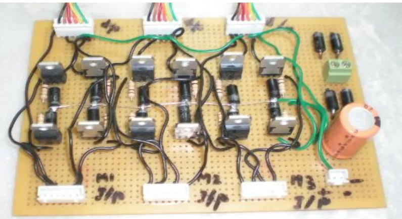
3.8 Hardware Module
The hardware for laser based guidance system for projectile has been made of sheet metal which is of low cost. Fig. 10 shows the hardware module of this paper which comprises of all the three stepper motors in it.
IV. SOFTWARE DESCRIPTION
In this paper for software simulation we have used Embedded C language. The codes to actuate all the hardware components are written in embedded C language. Control algorithm has been developed and the corresponding codes are simulated in ATMEL Studio and the same has been checked in PROTEUS 7 platform. The simulated codes after verifying in PROTEUS 7 are dumped to an ATMEGA32 microcontroller via a programmer kit which is made of ATMEGA128. This chapter deals clearly about ATMEGA 32 microcontroller and about ATMEL Studio6 and PROTEUS 7 platform.
4.1 Atmega 32
The ATMEGA 32 is a low power CMOS 8-bit microcontroller based on the AVR enhanced RISC architecture [5]. By executing powerful instructions in a single clock cycle, the ATMEGA 32 achieves throughputs approaching 1 MIPS per MHz allowing the system designed to optimize power consumption verses processing speed.
4.2 Brief Description to ATMEGA 32
As explained above, ATMEGA 32 is based on the AVR enhanced RISC Architecture. The AVR core combines a rich instruction set with 32 general purpose working registers [5]. All the 32 registers in it are directly connected to the Arithmetic Logic Unit (ALU), allowing two independent registers to be accessed in one single instruction executed in one clock cycle. The resulting architecture is more code efficient while achieving throughputs up to ten times faster than conventional CISC microcontrollers. The ATMEGA 32 provides the following features:
32K bytes of In-System Programmable Flash Program memory with Read- While- Write capabilities, 1024 bytes EEPROM
2K byte SRAM, 32 general purpose I/O lines, 32 general purpose working registers
A JTAG interface for boundary scan,
On-chip debugging support and programming, Three flexible Timer/Counters with compare modes, Internal and External Interrupts,
A serial programmable USART,
A byte oriented two-wire serial interface,
10-bit ADC with optional differential input stage with programmable gain (TQFP package only), A programmable Watchdog Timer with Internal Oscillator,
An SPI serial port and six software selectable power saving modes, The idle mode stops the CPU while allowing the USART,
Two-wire interface, A/D Converter,
SRAM, Timer/Counters,
SPI port, and interrupt system to continue functioning.
The power-down mode saves the register contents but freeze the oscillator, disabling all other chip functions until the next external interrupt and hardware reset. In power- save mode, the asynchronous timer continuous to run, allowing the user to maintain a timer base while rest of the device is sleeping.
By combining an 8-bit RISC CPU with In-System Self –Programmable Flash on a monolithic chip, the Atmel ATMEGA32 is a powerful microcontroller that provides a highly-flexible and cost-effective solution to many embedded control applications. The ATMEGA 32 AVR is supported with a full suite of program and system development tools including: C compilers, macro assemblers, program debugger/simulators and in- circuit. 4.3 Atmel Studio 6
Atmel studio 6 is the integrated development platform(IDP) for developing and debugging Atmel AVR ® microcontroller based applications. The Atmel studio 6 IDP gives you a seamless and easy to use environment to write, build and debug your applications written in C/C++ assembly code.
4.4 PROTEUS simulation software
control over the drawing appearance, in terms of line widths, fill styles and fonts, etc. these capabilities are used to the full in providing the graphics necessary for circuit animation.
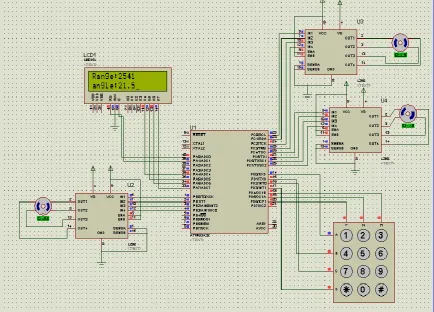
In this project paper three stepper motors working have been checked through Proteus simulation software. For getting the input keypad is used and the same has been displayed using LCD. The code build for laser based guidance system has been dumped in the ATMEGA 32 microcontroller. As per the code depending on the target range and angle and the missile velocity, the microcontroller will generate the required pulses to activate the three motors to generate the required laser beam trajectory. The missile will interpret the information contained in the laser beam and it will create its own correctional command and hit the target accurately. Fig. 4.1 shows the full schematic of laser based guidance system for projectile build in Proteus software.
Figure 11 Proteus schematic of laser based guidance system for projectile
V. CONTROL ALGORITHM
The Algorithm required to implement the laser based guidance system are as follows The ports of ATMEGA 32 controller has been initialized
Declaration of port has been done to indicate which port is allocated to keypad, LCD and stepper motors The input values such as range and angle has been obtained manually through keypad
The input values are applied to the control algorithm, so as to get the required pulses to activate all the three stepper motors by which the laser beam will generate the desired laser beam trajectory
The control algorithm includes the calculation of azimuth angle, initial elevation angle and the required elevation angle of laser beam and the linear movement steps for lens. They are
Total steps Azimuth = Angle/Step angle Step Angle for all the three stepper motor = 1.8 Elevation = Range / Missile velocity
Missile Velocity = 200 m/sec
Initial elevation steps = Elevation/Step angle Time of Flight = Range/900
Total steps elevation = Time of flight/0.1 sec For every 100msec = 1Step
Linear movement steps = 360 * No of rotations/ step angle
VI. RESULTS
Figure 12 Experimental setup of Laser based guidance system for projectile
The different output step angles obtained for the given target input are tabulated as shown in Table 6
Target Range Target Angle Azimuth angle Elevation angle Linear movement steps
2564 36.2 20.11 7.12 2800
3569 45.8 25.44 9.91 2800
4567 55.4 30.77 12.68 2800
5689 66.7 37.05 15.80 2800
6538 78.2 43.44 18.16 2800
7892 86.3 47.94 21.92 2800
Table 1 Tabulation of different step angles
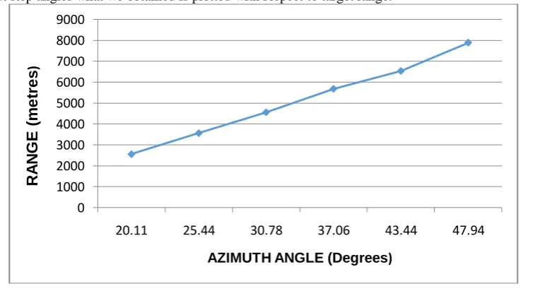
The output step angles what we obtained is plotted with respect to target range.
Figure 13 Target Vs Azimuth Angle 0
1000 2000 3000 4000 5000 6000 7000 8000 9000
20.11 25.44 30.78 37.06 43.44 47.94
R
A
N
G
E
(
m
e
tre
s
)
Figure 14 Target Range Vs Elevation angle
VII. CONCLUSION
In World War II it could take 9,000 bombs to hit a target the size of an aircraft shelter. Today we can do it with one laser-guided projectile. Laser guided projectile can be fired at targets ranging 1 to 8 Km. Though many projectiles are developed, they don’t find accuracy as in the reaching the target. The accuracy of these weapons earned them the well- known sobriquet of “smart weapons”. The Laser Guided projectile has established itself as a key component in today’s high-tech military technology. So compare to other guiding technique this technique provide high accuracy and use of low power laser will fool the laser warning system in enemy tank.
REFERENCES
[1] Bureau of Naval Personnel. Principle of Guided Missiles and Nuclear Weapons. NAVPERS 10784-B, 1st Rev.Washington, D.C.: GPO, 1972.
[2] Commander, Naval Ordnance Systems Command. Weapons Systems Fundamentals. NAVORD OP 3000, vols.2&3, 1st Rev. Washington, D.C.: GPO, 1971
[3] Lee, R.G., et al. Guided Weapons: Including Light, Unguided Anti-Tank Weapons. Pergamon Brassey’s Defence Weapons
[4] Systems & Technology Series, 1983. Stepping Motor Tutorial by Dr. Douglas W. Jones (http://www.cs.uiowa.edu/-jones/step/#introduction), Copyright 1995
[5] Atmega32-Internet Link: www.atmel/acrobat/doc2503.pdf [6] www.en.wikipedia.org
[7] http://sachin-robotics.blogspot.com/2008/01/how-to-build-microcontroller-based-html [8] http://www.microcontroller.com
0 1000 2000 3000 4000 5000 6000 7000 8000 9000
7.12 9.91 12.69 15.80 18.16 21.92
R
A
N
G
E
(m
e
tr
e
s
)