ISSN (e): 2250-3021, ISSN (p): 2278-8719
Vol. 05, Issue 05 (May. 2015), ||V1|| PP 45-55
Numerical Modelling Of Strength For Hull Form Components Of
A 700 Tonne Self-Propelled Barge Under Moment And
Operational Loading
Adumene Sidum and Nitonye Samson
Department of Marine Engineering, Rivers State University of Science and Technology Port Harcourt, Rivers State, Nigeria
Abstract: - The design of vessel especially self propelled sea going barge is highly complex, considering the various component needed to analyze. There are basic principle and method that is confirmed to the Lloyd’s Register which are used in the analysis of this work. The principle of stability ratio and strength was used against that of similarities of vessels for the determination of the barge dimensions. A numerical program was used to check the result obtained using the dimensional analysis to calculate the centre of gravity of the self-propelled barge transversely, longitudinally and vertically. The still water moment and wave moment modeling was carried out to obtained the maximum bending moment and stresses that the structure would undergo during operation. The result obtained shows that the barge would withstand a maximum bending stress of 83.33MN/m2 with a wave bending moment at sagging condition of about 18.846MNm. The vessel exhibit mechanical strength and stability of moment loading condition and will withstand various form of stresses that would arise during operations.
Keywords: - Barge, Self Propelled, Stability, Ship Resistance, Hull, Displacement
I.
INTRODUCTION
A barge is usually a flat bottom vessel mainly used as cargo tankers, equipment supply carriers, Crain platforms and support accommodation bases in offshore operation. Though most barges are pushed or pulled by tug boat, this barge considered is to be a self propelled barge (Nitonye et al 2003).
Obviously, sufficiency of strength is one very important quantity necessary for the safety of a barge on the sea voyage. If the barge structure is not sober enough for the sea and the load, it impress upon it, it will fail in the primary function. The entire structure of the barge comparison of a steel plate, section and build-up girder well interconnected in various ways to provide sufficient strength to withstand the forces acting upon the vessel under every condition of service (Newton, 1970).
The framing system and analysis is adopted in order to meet the strength standard. There are two types of framing system adopted; the transverse and the longitudinal system. A transverse system of framing made up of floors, side frames and deck beam all join effectively together to encircle the hill from port to starboard and effort transverse strength. A longitudinal framing system consist of longitudinal plead member of the shell, deck and bulk head supported by deep transverse web frames spaced between transverse bulkhead running fore and all which contribute to the longitudinal strength (Munro-Smith, 1997).
The longitudinal framing system set the orientation of plating stiffeners longitudinal which greatly improve the artificial bulking strength of the plating under longitudinal compressive stress. In the analysis of self-propelled barge strength, the longitudinal system of framing is adopted so as to withstand stress which occurs when the vessel is hogging or sagging in cause of operation (Stephen, 2004).
A self-propelled barge is a single bottom vessel and the keel composes of the floors plate and sea longitudinal bulkhead which run fore and aft. The vertical keep to the longitudinal bulkhead is made watertight throughout the length between perpendiculars (LBP).
The hull of the self-propelled barge provides water-light covering; withstand water pressure, shearing stress, tensile and compressive stresses. The girders, beams and stiffeners on the hull of the self propelled barge are disposed such that they from a rigid connection with the shell planting. The weight of the hull and its members form a good proportion of the total weight of the barge.
The general need for intact stability criteria arises due to the fact that actual ship designs suffer from specific phenomena in rough weather that did not occur at those designs which were relevant when the intact stability code was developed (Barber, 2002). The design of this system is to have a structure where the criteria will account for a minimum stability limit require to that these minimum stability standards will provide the barge with sufficient safety. Hence the dynamic criteria of the ship were developed to have the following structural criteria to avoid large rolling angles, large acceleration to avoid broaching. Besides broaching which is considering a maneuvering problem, pure loss of stability and parametric rolling was discovered to be relevant phenomena which was related to a large rolling angles, provided the rolling damping is sufficient. The strengthening of bulkheads against failure demands that all bulkheads should have the same strength that will withstand water-pressure after damage has been done. Unsupported bulkheads of full loads drafts must be avoided (Jerzy, 2004).
Many researchers in this field make use of both their experience and principal of similarity of vessels in the determination of their principal dimension, while that of weight and centre of gravity are carryout through the inclining experiment. But in this work, the principal dimensions and the centre of gravity is determine through the use of stability ratio and centre of gravity by three dimensional analysis calculations. The structure of the barge is designed to avoid sudden discontinuity of strength among the structural members in order to ease out stress concentration and serious local stain. The barge is designed with sufficient stability to render perfectly safe in any weather conditions and allow a margin of safety against the possible effect by increase of water.
II.
MATERIALS AND METHODS
2.1 DESIGN ANALYTIC MODEL
The design analysis is based on the principle of comparing two similar vessels and the principle of stability ratio. By applying the geometrically similar ship, the design displacement was approximated from the known displaced.
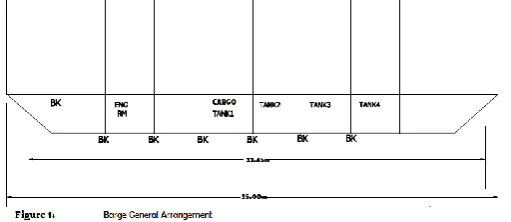
Table 1: Principal particulars of 700 tonnage self propelled barge.
PARTICULARS UNIT VALUE
Length Overall m 35.00
Length Between Perpendicular
m 33.45
Breadth molded m 10.00
Breadth Extreme m 10.30
Speed Knots 8.1
Wetted surface
area
m2 2498.96
Depth m 3.5
Draught m 2.5
Tunics Capacity m3 560
Stiffener spacing = 500mm Density of steel =7.89ton/m2 Type of section angle from 102x102 x7.8 = 12.06kg/m (4)
LONGITUDINAL BULKHEADS
Steel plate thickness = 8mm Height = 3.5m Length of bulkheads = 26.95m Mass = 0.008x26.95x3.5x7.89 = 5.95tons
TRAINSVERSE BULKHEADS
Steel plate thickness = 8mm Length of bulkheads = 10.0m Height = 3.5m Number of bulkheads = 8
Mass = 10x3.5x7.89x0.008x8 = 17.67tons
SIDE PLATE
Mass = (33.45x3.5x1x0.01x7.89) = 18.47tons
BOTTOM PLATE
Length = 31.45 Steel plate thickness = 10mm Breadth = 10m Number of plate = 1
Mass = 31.45x10x0.01x7.89 = 24.81tons
DECK PLATE
Length = 35.00m Steel plate thickness = 10mm Breadth = 10.0m Number of plate = 1
Mass = 35x10x0.01x7.89 = 27.62tons
FORE PLATE
Length = 3.80m Breadth = 10.0m Thickness = 10mm Mass = 3.80x0.01x7.89 = 3tons
AFT PLATE
Length = 4.3m Breadth = 10.0m Thickness = 10mm Mass = 4.2x10x0.01x7.89 = 3.39tons
BRACKET
Steel of plate = 8mm Number of brackets = 160 Area = 0.02m2
Mass = 0.02x0.008x7.89x160 = 0.20tons
LONGITUDINAL STIFFENER ON DECK
Longitudinal space = 500m Breadth = 10m Number of longitudinal = 20 Length of longitudinal = 35.00 Section 102x102x7.8 = 1ks/n
Mass = 35.00x12.00x20 = 8442kg = 8.442tons
LONGITUDINAL STIFFENER ON SIDE PLATE
Height = 3.5m Number of longitudinal = 14 Length of longitudinal = 33.45m Mass = 33.45x12.06x14 = 5.67tons
LONGITUDINAL STIFFENER ON BOTTON PLATE
Breadth = 10m
Length of longitudinal = 3.8+4.3+31.45 = 39.55m Mass = 39.55x12.06x18 = 8.59tons
VERTICAL STIFFENER ON BULKHEAD (Transverse)
Total Length of Stiffener
on Bulkhead = 441.0m Mass = 441.0x12.06 = 5.31tons
VERTICAL STIFFENER ON LONGITUDINAL BULKHEAD
Length of stiffener = 185m Mass = 185.0x12.06 = 2.28tons
TRANSVERSE WEB FRAMES SIDE TO SIDE
Total number of frame = 5
Total length of web with frame = (3.5x4) + (4.4x4) = 31.6m
FLANGE
(2.9x4) + (4.4x4) = 29.2m = total flange length
TOTAL TRANSVERSE WEB FRAME LENGTH
31.6x29.2 = 60.8m
Mass = 60.8x0.01x450x7.89 = 10.79tons
2.2 WEIGHT AND CENTRE OF GRAVITY MODEL
The position of the centre of gravity of the self–propelled barge can be modeled by analytical or experimental method. In evaluating the centre of gravity of a barge, different particle and the moment of each particle is calculating by multiplying it’s weight by the distance from a reference plane, the weight and moment of all the particles added as the total moment divided by the total weight. The centre of gravity is loaded only when the three planes has been established. In barge calculation, the reference plane generally used are horizontal plane through the base line, for the vertical transverse plane either through amidships or through a forward perpendicular for the longitudinal location (LCG) as a vertical plane through the centre line to the transverse position (TCG) (Munro-smith, 1997). From the analysis we have
K G from the keel of the barge = 243.449/136.02 = 1.7898 Centre of gravity from the centre of transversely
= 0.1458/136.02 = 0.00107m
It is therefore important that the weight and location of the centre of gravity be strolled at an early stage in the design of the barge. The weight ands and the centre of gravity model are major film in determining the adequately of the ship’s stability.
2.2.1 BARGE STRENGTH MODEL
The strength of a structure indicates its ability to withstand the stresses or loads imposed on it. Ship structure is designed to provide adequate strength without yielding under the normal conditions of loading which it can be expected to experience.
Loading stress
Mass of the steel structure = 142tons Mass of engines = 50tons Mass of cargo = 508tons
Area (A2) = Length x breadth = 29 x 10 =290m 2
(1). Area (A1) = Area a1 + Area a2 (2)
Area a1 =1/2 base x weight= ½ x3.0.x3 =4.5m2 (3)
Area a2 = length x breadth = 3x10 = 30m2
Therefore are a1 = 4.5 +30 =34.5m 2
Total A1= 2A1= 34.5x 2 = 69m2
Total area of the structure = 2A1 +A2 = 69+290 = 359m2
Weight of area (A2) (4)
Uniformly distributed weight along the length of area
A2 = (5)
Weight of area (6)
Weight of area
Weight of area
Weight distribution on area (7)
Weight distribution m area
(8) Where x varies from 0 to 3
Total weight distribution on area (a1) average
Weight distribution on area (A1)
= weight a1 + weight a2 = 0.89 + 3.957 = 4.84t/m
Total weight distribution on area (A1)
= 2A1= 4.847 x 2 =9.694t/m
Uniformly distribution load along the entire structure = 2A1+A2 = 9.694+3.957
=13.651t/a Weight at each point:
At engine point
At cargo space
Buoyancy force
2.2.2 WEIGHT RESULTANT DIAGRAM
2.2.3 SHEARING FORCE AND BENDING MOMENT MODEL
A self propelled barge of length overall 35m and length between perpendicular 33.45m has the breadth of 10m, depth 3.5m is loaded.
The barge is now assumed to poise statically on a wave of cosine form in which case the height of the wave of any point about the still water wave is given as.
(9)
At a quarter length
Buoyancy moment = (10)
Mass moment (11)
Net moment = buoyancy moment- mass moment = 2926-2142.56 =783.44t/m Still water bending moment = 783.44 x 9.81 x 153=7.694MNm
Considering the wave as a cosine form and with the crest at the ends
H= = (12)
Integrating the buoyancy gives the sharing force due to the wave
(13)
Wave shearing force =
Integrating the wave shearing forces gives the wave bending moment [2] Wave bending moment =
The condition that the bending moment is zero at
Pulling
Wave bending moment at sagging condition = still water moment + wave moment = 7.6942+11.152= 18.846MNm
2.2.4 MODULUS AND STRESS MODEL
The mild steel properties include ultimate tensile strength (400-49MN/m2) or
(26-32 ton/in2), Yield stress (230-250mn/m2) or (15-16ton/m2) and Shearing strength (22ton/m2)
Stress (14)
Factor of safety (15)
Unit area (16)
Sm= sector modulus, = unit stress
(18)
C= distance from the neutral axis (a line parallel to the base line drawn through the centroid of all the effective longitudinal strength members comprising the sector
I= sectional moment of Inertia about the neutral axis.
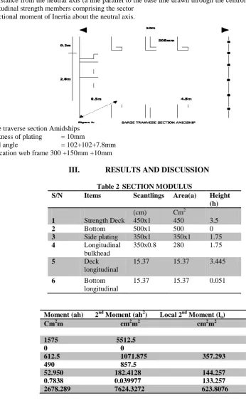
Barge traverse section Amidships Thickness of plating = 10mm
Equal angle = 102+102+7.8mm Fabrication web frame 300 +150mm +10mm
III.
RESULTS AND DISCUSSION
Table 2 SECTION MODULUS
S/N Items Scantlings Area(a) Height
(h)
1 Strength Deck (cm) 450x1
Cm2
450 3.5
2 Bottom 500x1 500 0
3 Side plating 350x1 350x1 1.75
4 Longitudinal bulkhead
350x0.8 280 1.75
5 Deck longitudinal
15.37 15.37 3.445
6 Bottom longitudinal
15.37 15.37 0.051
1610.74
Moment (ah) 2nd Moment (ah2) Local 2nd Moment (lo)
Cm2m cm2m2 cm2m2
1575 5512.5
0 0
612.5 1071.875 357.293
490 857.5
52.950 182.4128 144.257
0.7838 0.039977 133.257
Figure 9: Load distribution curve on the barge in operation
Figure 10: Weight distribution curve of the vessels components
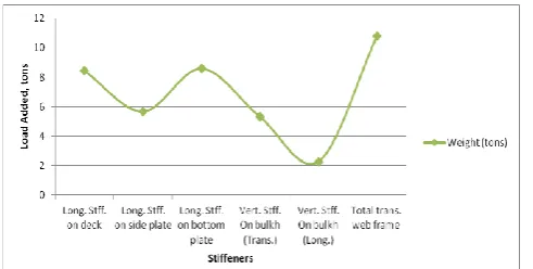
Figure 11: Stiffener induced load distribution on the vessel components
The results indicated that the point load (weight) is high at cargo space accounting for about 31% of the total force acting on the vessel as shown in figure 9. Figure 10 indicated that the deck plate member have a weighted ton of 27.62. This represents about 27.3% of the overall ton weight of the vessel.
The stiffener induced load on the vessel component is indicated by figure 11. This show that the longitudinal stiffener on the bottom plate induced a weighted tons of about 8.59, representing about 28.4% of the total weight induced by the stiffeners. The transverse web frame length has a total weight induced of about 10.79tons. For Stress Modeling,
Neutral axis above base Zb=
2nd moment of area of half section about base = = 764.3272+ 623.8076
= 8248.1348cm2m2 (20) Less area x Z2 base
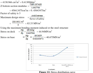
= 4130.966 cm2m2 = 0.4130966m3 Z bottom section modulus =
= 4564.3475cm2m = 0. 45643475m3 Factor of safety is 3
Maximum design stress =
= = 83.33 MN/m2
Using the maximum bending moment induced or the steel structure Stress on deck = = = 44.94MN/m2
Stress on base = 40.675MN/m2
Figure 12: Stress distribution curve
The stress induced curve show that the deck experiences much stress during loading and operation. It indicated that the maximum limiting stress (vessel overall design stress) is 83.33MN/m2, which must not be exceeded to ensure a safe operation of the vessel. This provides an operational loading limit for the barge operators.
Also the principle of the beam-draught ratio was useful in the determination of the initial stability and nature period of roll, since the barge is a box shape where the point of metacentre from the centre of gravity of buoyancy (BM) = B2/12d. An increase in the beam means increase of the metacentre from the centre of buoyancy. With an increase in breadth draught ratio, there would be an increase in resistance and transverse stability. A decrease in the ratio would increase the rolling period of the barge and less resistance. Hence the ratio must be such that vessel remains stable at all condition of loading with less resistance to ahead or astern motion.
The draught-depth ratio was extremely important to large angle stability in this research since it determine the point of deck edge immersion and reserve of buoyancy of a vessel for survivability. The greater the freeboard at given draught, provided the centre gravity is not too high, the longer the sighting lower becomes at considerable angle of inclination and also the greater the range of stability. It therefore confirms that with a good beam, and metacentric height (GM), unless combined with sufficient freeboard, there is no guarantee for either good range or lever of stability. Hence an increase in the ratio leads to a decrease in reserve of buoyancy which endanger the life of the crews and vessel in case of any bilge(s) to one or two compartments.
The determination of the centre of gravity shows that references were taken from the three axis viz, from the keel and amidships of the vessel. The centre of gravity of the lightship was numerically obtained. It involves the determination of the mass and centroid of every item making up the total mass. The result shows that the vertical centre of gravity KG is low, hence the barge is not top heavy which means that the structural reposition of the material is in accordance to the specification.
The longitudinal centre of gravity from amidships shows that it is some distance aft of the amidships which is of good importance for the efficient operation of the rudder and propeller without any statistical disruption.
The strength of the model of the vessel assessed the various forces to which the barge structure is subjected during its lifetime; the results of the analysis indicated that there is variation in the weight of the structure throughout the length of the barge. Although the total weight of the vessel is balanced by the total force of buoyancy, neither is it uniformly distributed throughout the vessel length. The result show that the weight of each ends section exceeds the buoyancy which they provide at these sections, will since deeper into the water. The load curve results indicate that there is difference between weight and buoyancy of each section throughout the length of the barge. In still water, the uneven loading which occurs throughout the length of a ship varies considerably with different conditions which may reach very high values.
In waves, additional bending moments are created. These being brought about by the uneven distribution indicate the loading, the effect of the still water and wave buoyancy where the ship is constantly changing from hogging to sagging condition. The result obtained from the still water and wave moment shows that the barge would be sagging at the amidships. A barge is like an I-Girder in a loaded condition with a wave crest or through amidships, the shearing force attains its maximum value in the vicinity of the neutral axis at about a quarter of the barge’s length each end.
The minimum shear force is extended at the keel and on the top deck while the maximum bending moment occurs at the keel and top deck.
The longitudinal stress was determined from the moment of inertia, section modulus at amidships.
IV.
CONCLUSION
The research results obtained indicate that the deck would be in a compression stress while the bottom would be on a tensile stress. The stress obtained is within the allowable stress hence the vessel structure would be able to withstand the stresses that she will encounter during operations. Also the results of the longitudinal transverse vertical centre of gravity and metacentric height showed that the barge would be stable at all normal condition of loading.
In order to obtain the moment of inertia giving a safe stress with maximum material, the materials are disposed further away from the neutral axis and most efficiently converted to have its designed share of the stress. Hence the (strength) stress which the structure needed is withstands compare with the maximum allowable yield stressed from Lloyd’s handbook indicated that the barge structure would withstand the hogging and sagging and six motion of gyration that would undergo during the course of its service.
The analysis revealed that the hull form components weigh a total mass of 136.0ton and the moments along the X, Y and Z components are 0.1458 ton-metre, -38.862 ton-metre and 243.449 ton-metre respectively. This show that the barge can withstand a maximum stress of 83.33MN/m2, haven a bending moment induced on the deck at 44.94MN/m2 maximum and on the base at 40.6759MN/m2 maximum.
REFERENCE
[1] Barter, B. (1970). Know your own ship. In: Center of gravity 28th Ed. 13 (373)
[2] Barber, D. (2002). In Bulk Carrier- bulkhead and survivability: SEAWAYS-International Journal of the nautical institute.
[3] Derret, D. R. (1979). “Ship Stability”. In: Transverse Stability (pp. 99); Forms Coefficient (pp. 59); Curve of shear forces and bending moment (pp 327); Final centre of gravity (pp 89). 5th Ed. (394) [4] Heikki, S. (2010). Possibilities in ship and propulsion design, kiss: cargo transport vessel trends, (211). [5] Hinton, P. In: Adoption of double hulls for tankers and bulk carriers. Safety at Sea 27 (413)
[6] Jerzy, K. (2004): In stern and stern corrections for a deflected vessel: HANSA-International Maritime Journal
[7] Kenneth, C. B. (1969). “Basic Naval Architecture”. In: Combine viscosity and gravity resistance (pp. 502); Wetted surface of abnormally shallow draft forms (pp.108). 6th Ed.
[8] Lloyd’s Register (1996). “Rules and regulations for the classification of ships part 3: ship structures, section 6, principal particulars 6.1.1
[9] Munro-Smith, R. (1997). “Ships and Naval Architecture” In: Bending moment (pp. 241); Change of trim (pp. 192); Displacement to a trimmed waterline (pp.193-194); Moment to change trim by one centimeter (pp. 195); Modulus and stress calculation (pp.232); Seaworthiness (pp. 233); Transverse stability (pp. 165). 2nd Ed. (325)
[10] Munkle, W. (1981). “Naval Architecture for marine engineers”. In: Determination of principal dimension (pp. 389); Load lines (pp. 40); Structural strength (pp.155-163); Theoretical laws of motion of a body through a fluid (pp.205); Forces on a ship at sea (pp.156); Characteristics of shearing force and bending moment (pp. 159-162); Ship development (pp.1). 2nd Ed. (407)
[12] Nitonye Samson, Ezenwa Ogbonnaya and Kuvie Ejabefio, (2013) Stability Analysis for the Design of 5000-Tonnes Offshore Work Barge, International Journal of Engineering and Technology,(IJET) United Kingdom Vol.3 No 9: pp849-857 (http://www.ijet.journal.org)
[13] Ralf, H., Stefan, K. In: Development of dynamic stability criteria; HANSA- International Maritime Journal.
[14] Rawson, K. J., Tupper, E. C. (1998), “Basic ship theory” In: Influence of form in sea keeping (pp. 514). 4th Ed. (702)
[15] Richard, B. C., Mathew, G. F., Owen, A. O., Harold, F. R., Vito, L. R., John N. (1977). “Principles of Naval Architecture” In: Weight and centre of gravity determination (pp.54); Wetted surface (pp.42); Metacentric height-Floodable length (pp. 70); Transverse and longitudinal framing (pp.185); Effect of free liquids (pp. 78). 4th Ed. (827)
[16] Samuel, E. K., Paul, A. R., Andrew, J., Ian, D. W. (2004) In: Artificial intelligence for automatic container stowage planning optimization: HANSA- International Maritime Journal