Page 370 www.ijiras.com | Email: contact@ijiras.com
Production Of Biogas From Various Raw Materials And
Performance Analysis On IC Engines
T. Harichandra
Asst, Professor, Mechanical Engineering, Roever Engineering College
A. Captan Prabakaran
Asst, Professor, Mechanical Engineering, Roever Engineering College
I. INTRODUCTION
Due to scarcity of petroleum and coal it threatens supply of fuel throughout the world also problem of their combustion leads to research in different corners to get access the new sources of energy, like renewable energy resources. Solar energy, wind energy, different thermal and hydro sources of energy, biogas are all renewable energy resources. But, biogas is distinct from other renewable energies because of its characteristics of using, controlling and collecting organic wastes and at the same time producing fertilizer and water for use in agricultural irrigation. Biogas does not have any geographical limitations nor does it require advanced technology for producing energy, also it is very simple to use and apply.
A. ALTERNATIVE FUELS
Alternative fuels, known as non-conventional or advanced fuels, are any materials or substances that can be used as fuels, other than conventional fuels. Conventional fuels include: fossil fuels (petroleum (Oil), coal, Propane, and natural gas), as well as nuclear materials such as uranium and
thorium, as well as artificial radioisotope fuels that are made in nuclear reactors, and store their energy. Some well-known alternative fuels chemically stored electricity (Batteries and fuel cells), hydrogen, non-fossil methane, non-fossil natural gas, vegetable oil, and other biomass sources.
Alternative fuels are derived from resources other than petroleum. Some are produced domestically, reducing our dependence on imported oil, and some are derived from renewable sources. Often, they produce less pollution than gasoline or diesel.
BIO FUEL: Bio fuels are also considered a renewable source. Although renewable energy is used mostly to generate electricity, it is often assumed that some form of renewable energy or a percentage is used to create alternative fuels.
BIOMASS: Biomass in the energy production industry is living and recently dead biological material which can be used as fuel or for industrial production.
BIOGAS: Biogas typically refers to a gas produced by the biological breakdown of organic matter in the absence of oxygen. Organic waste such as dead plant and animal material, animal feces, and kitchen waste can be converted into a gaseous fuel called biogas.
Abstract: Cow manure is an excellent substrate for biogas production in anaerobic digesters, though the gas yield from a single substrate is not high. However mixing cow manure with other kind of solid waste materials like maize, pig waste, olive oil, sheep waste, fruit/vegetables, food waste in co-digestion can optimize the production of biogas. The main objective of the project work is to increase the production of biogas especially methane content by mixing cow manure with rice husk and azollacaroliniana by means of anaerobic digestion. The influence of mixing concentration of azolla on the properties of biogas is going to be investigated in this research work. The gas produced from the substrate will be further tested in SI engine at the varying load conditions. The performance and emission characteristics of an IC engine using the biogas.
Page 371 www.ijiras.com | Email: contact@ijiras.com Biogas originates from biogenic material and is a type of
bio fuel; biogas is produced by the anaerobic digestion or fermentation of biodegradable materials such as biomass, manure, sewage, municipal waste, green waste, plant material, and crops. Biogas comprises primarily methane (CH4) and
carbon dioxide (CO2) and may have small amounts of
hydrogen sulphide (H2S), moisture and siloxanes.
The gases methane, hydrogen, and carbon monoxide (CO) can be combusted or oxidized with oxygen. This energy release allows biogas to be used as a fuel. Biogas can be used as a fuel in any country for any heating purpose, such as cooking. It can also be used in anaerobic digesters where it is typically used in a gas engine to convert the energy in the gas into electricity and heat.
Biogas can be compressed, much like natural gas, and used to power motor vehicles. In the UK, for example, biogas is estimated to have the potential to replace around 17% of vehicle fuel.
Biogas is a renewable fuel, so it qualifies for renewable energy subsidies in some parts of the world. Biogas can also be cleaned and upgraded to natural gas standards when it becomes bio methane.
Compound Chem. %
Methane CH4 50-65
Carbon dioxide CO2 25-50
Nitrogen N2 0-10
Hydrogen H2 0-1
Hydrogen sulphide H2S 0-3
Oxygen O2 0-0
Table 1.1: Chemical Composition of Biogas in General
B. INTERNAL COMBUSTION ENGINE
The internal combustion engine is an engine in which the combustion of a fuel (Normally a fossil fuel) occurs with an oxidizer (Usually air) in a combustion chamber. In an internal combustion engine, the expansion of the high-temperature and high -pressure gases produced by combustion apply direct force to some component of the engine.
This force is applied typically to pistons, turbine blades, or a nozzle. This force moves the component over a distance, transforming chemical energy into useful mechanical energy. The first functioning internal combustion engine was created by Etienne Lenoir.
The term internal combustion engine usually refers to an engine in which combustion is intermittent, such as the more familiar four-stroke and two piston engines, along with variants, such as the six-stroke piston engine and the wankel rotary engine.
A second class of internal combustion engines use continuous combustion: gas turbines, jet engines and most rocket engines, each of which are internal combustion engines on the same principle as previously described.
a. TYPES OF IC ENGINE
There are two main types of IC engines: spark ignition (SI) engines (Petrol or gasoline engine) and compression ignition (CI) or diesel engine. Both these engines are further classified as 2-stroke and 4-stroke engine.
Internal combustion engines, more popularly known as IC engines, are the ones in which the combustion of fuel takes place inside the engine block itself. After combustion of fuel, much heat energy is generated; this is converted into mechanical energy.
There are two types of IC engines: rotary and reciprocating engines. In rotary engines, a rotor rotates inside the engine to produce power. In the case of the reciprocating engines, a piston reciprocates within a cylinder. The reciprocating motion of the piston is converted into the rotary motion of the vehicle's wheels. In automobiles, reciprocating engines are used. They are the most widely used type of engine.
Reciprocating engines are classified into two types: spark ignition (SI) engines and compression ignition (CI) engines. Since reciprocating engines are the most widely used engines, they have become synonymous with the name IC engines. It is this reason that even the IC engines are broadly classified into two types: SI engines and CI engines.
b. SI ENGINE
The engine in which the cycle of operations is completed in two revolutions (720º) of the crank shaft or four strokes of the piston is known as the four stroke engine. One stroke is completed when the piston moves from top dead centre to bottom dead centre or when the crank rotates through 180º. If the combustion of the fuel-air mixture takes place with the help of spark plug then it is known as four strokes spark ignition engine. The SI engine operates at a compression ratio of 6 to 10.
C. CELLULOSE MATERIAL
In this project work the cellulose material AZOLLA and RICE HUSK is used to increase the methane gas production.
AZOLLA
In Tamilnadu, the azolla is available at kanyakumari sea beaches. It is nothing but the green plant in which having the ability for doubling the biomass.
Azolla floats on the surface of water by means of numerous Small, closely overlapping scale-like leaves, with their roots hanging in the water. They form a symbiotic relationship with the cyanobacteriumAnabaena azollae, which fixes atmospheric nitrogen, giving the plant Access to the essential nutrient.
This has led to the plant being dubbed a "super-plant", as it can readily colonies areas of freshwater, and Grow at great speed - doubling its biomass every two to three days.1989).
Sculthorpe (1967), reports that Azollais harvested in large quantities from water bodies in parts of tropical Africa, India, and Southeast Asia and utilized as fodder for cattle and pigs.
RICE HUSK
Page 372 www.ijiras.com | Email: contact@ijiras.com It improves methane production and reduces the digestion
period.
II. SCOPE OF THIS PROJECT Production of bio gas
Improving the percentage of methane in bio gas The performance analysis on SI engine by using bio gas The emission test on SI engine
III. BIOGAS
BIOGAS is produced by bacteria through the bio-degradation of organic material under anaerobic conditions. Natural generation of biogas is an important part of bio-geochemical carbon cycle. It can be used both in rural and urban areas.
A. CHARACTERISTICS OF BIOGAS
Composition of biogas depends upon feed material also. Biogas is about 20% lighter than air has an ignition temperature in range of 650 to 750 0C an odorless & colorless gas that burns with blue flame similar to LPG gas. Its caloric value is 20 Mega Joules (MJ) /m3 and it usually burns with 60 % efficiency in a conventional biogas stove.
This gas is useful as fuel to substitute firewood, cow-dung, petrol, LPG, diesel, & electricity, depending on the nature of the task, and local supply conditions and constraints.
Biogas digester systems provides a residue organic waste, after its anaerobic digestion(AD) that has superior nutrient qualities over normal organic fertilizer, as it is in the form of ammonia and can be used as manure.
Anaerobic biogas digesters also function as waste disposal systems, particularly for human wastes, and can, therefore, prevent potential sources of environmental contamination and the spread of pathogens and disease causing bacteria. Biogas technology is particularly valuable in agricultural residual treatment of animal excreta and kitchen refuse (residuals).
PROPERTY LPG NATURAL
GAS
BIOGAS
Lower heating
value(MJ/kg) 45.7 50 17
Ignition
Temperature 405-450
0C 5400C 650-750 0C
Normal Density 2.26 0.79 1.2 kg/m3
Stoichiometric
ratio of methane 15.5 17.3 9.5:1 to 10:1
Slow flame
velocity 0.38m/s 0.34m/s 0.290 m/s
Range of
flammability 2.15 to 9.6% 5 to 15%
4-14% which gives good combustion
efficiency
Octane number 103-105 120 130
Calorific value 27800kcal/m3
12000-14000kcal/m3 35.390 MJ/m3 Table 3.1: Fuel Properties
B. PROPERTIES OF BIOGAS
Change in volume as a function of temperature and pressure.
Change in calorific value as function of temperature, pressure and water vapour content.
Change in water vapour as a function of temperature and pressure.
It is colorless, odorless, and tasteless.
Composition of biogas is never constant. It is non-toxic component.
C. FACTORS AFFECTING YIELD AND PRODUCTION OF BIOGAS
Many factors affecting the fermentation process of organic substances under anaerobic condition are,
The quantity and nature of organic matter The temperature
Acidity and alkanity (PH value) of substrate The flow and dilution of material
3.4 Benefits of Biogas Technology
It is light fuel gas It mixes easily with air
It is highly resistant to knocking
Due to uniform distribution thermal efficiency is higher Biogas has a high octane number
It reduces pollution
Higher compression ratio can be used with biogas Plants capital cost is low
Domestic fuels for burners used in kitchen Not toxic to skin
D. DISADVANTAGES OF BIOGAS
The biogas yields are lower due to the dilute nature of substrates.
The only improvement in the process can be brought about by optimizing the environmental conditions of the anaerobic digestion.
Biogas contains some gases as impurities, which are corrosive to the metal parts of internal combustion engines.
Storage problem.
E. BIOGAS AS A VEHICLE FUEL
Utilization of biogas in the transport sector is a technology with great potential and with important socio-economic benefits. Biogas is already used as vehicle fuel in countries like Sweden, Germany and Switzerland. The number of private cars, public transportation vehicles and trucks driven on biogas (bio methane) is increasing. Bio methane can be used as fuel in the same way and by the same vehicles like the natural gas. An increasing number of European cities are exchanging their diesel buses with bio methane driven ones.
Page 373 www.ijiras.com | Email: contact@ijiras.com the luggage compartment, and a gas supply system, in addition
to the fossil fuel system. There are also specially built biogas vehicles, which are optimized for better efficiency and more convenient placement of gas cylinders, without losing luggage space.
The biogas is stored at 200 to 250 bars, in pressure vessels, made of steel or aluminium composite materials.
Today, more than 50 manufacturers worldwide offer some 250 models of commuter, light and heavy duty gas driven vehicles.
Heavy duty vehicles can be converted to run on methane gas only, but in some cases also dual fuel engines are used. A dual fuel engine uses a diesel injection system and the gas is ignited by injection of a small amount of diesel oil. Dual fuel engines require less engine development and maintain the same drive ability as a diesel vehicle. However, emission values are not as low as for the corresponding specially built gas vehicles and the engine technology remains a compromise between spark ignition and diesel engine. Bio methane vehicles have substantial overall advantages compared to vehicles equipped with petrol or diesel engines.
The overall carbon dioxide emissions are drastically reduced, depending on the feedstock substrate and origin of electricity (fossil or renewable) used for gas upgrading and compressing.
Emission of particles and soot are also drastically reduced, even compared with very modern diesel engines, equipped with particle filters. Emissions of NO and Non Methane Hydrocarbons (NMHC) are also drastically reduced. Upgraded biogas (bio methane) is considered to have the highest potential as vehicle fuel, even when compared to other biofuels. The potential of biogas for the transport sector is even higher, if waste is used as feedstock, instead of energy crops.
F. BIOGAS PRODUCTION PROCESS
A typical biogas system consists of the following components:
Manure collection Anaerobic digester Effluent storage Gas handling Gas use.
Biogas is a renewable form of energy. Methanogens (methane producing bacteria) are last link in a chain of microorganisms which degrade organic material and returns product of decomposition to the environment.
G. BIOGAS PLANTS
There are two types of plants Fixed dome type
Floating dome type
H. PRINCIPLES FOR PRODUCTION OF BIOGAS Organic substances exist in wide variety from living beings to dead organisms. Organic matters are composed of Carbon (C), combined with elements such as Hydrogen (H),
Oxygen (O), Nitrogen (N), and Sulphur(S) to form variety of organic compounds such as carbohydrates, proteins & lipids. In nature MOs (microorganisms), through digestion process breaks the complex carbon into smaller substances.
There are 2 types of digestion process: Aerobic digestion.
Anaerobic digestion.
The digestion process occurring in presence of Oxygenis called Aerobic digestion and produces mixtures of gases having carbon dioxide (CO2), one of the main ―green houses‖ responsible for global warming.
The digestion process occurring without (absence) oxygenis called anaerobic digestion which generates mixtures of gases. The gas produced which is mainly methane produces 5200-5800 KJ/m3 which when burned at normal room temperature and presents a viable environmentally friendly energy source to replace fossil fuels (non-renewable).
I. IANAEROBIC DIGESTION
It is also referred to as biomethanization, is a natural process that takes place in absence of air(oxygen).
It involves biochemical decomposition of complex organic material by various biochemical processes with release of energy rich biogas and production of nutrious effluents.
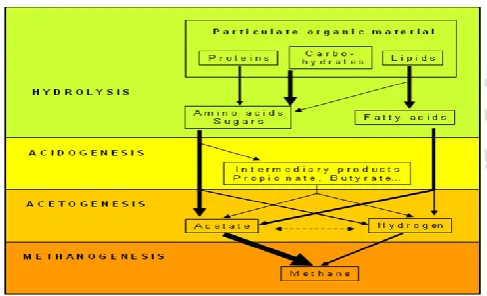
J. BIOLOGICAL PROCESS (MICROBIOLOGY) HYDROLYSIS
ACIDIFICATION METHANOGENESIS
HYDROLYSIS: In the first step the organic matter is enzymolysed externally by extracellular enzymes, cellulose, amylase, protease & lipase, of microorganisms. Bacteria decompose long chains of complex carbohydrates, proteins, & lipids into small chains. For example, Polysaccharides are converted into monosaccharide. Proteins are split into peptides and amino acids.
ACIDIFICATION: Acid-producing bacteria, involved this step, convert the intermediates of fermenting bacteria into acetic acid, hydrogen and carbon dioxide. These bacteria are anaerobic and can grow under acidic conditions. To produce acetic acid, they need oxygen and carbon. For this, they use dissolved O2 or bounded-oxygen. Hereby, the acid-producing bacteria create anaerobic condition which is essential for the methane producing microorganisms. Also, they reduce the compounds with low molecular weights into alcohols, organic acids, amino acids, carbon dioxide, hydrogen sulphide and traces of methane. From a chemical point, this process is partially endergonic (i.e. only possible with energy input), since bacteria alone are not capable of sustaining that type of reaction.
Page 374 www.ijiras.com | Email: contact@ijiras.com marine sediments), and in marshes. They are basically
anaerobic and very sensitive to environmental changes, if any occurs.
The methanogenicbacteria belong to the archaebacter genus, i.e. to a group of bacteria with heterogeneous morphology and lot of common biochemical and molecular-biological properties that distinguishes them from other bacteria‘s. The main difference lies in the makeup of the bacteria‘s cell walls.
SYMBIOSIS OF BACTERIA
Methane and acid-producing bacteria act in a symbiotical way. Acid producing bacteria create an atmosphere with ideal parameters for methane producing bacteria (anaerobic conditions, compounds with a low molecular weight).
On the other hand, methane-producing microorganisms use the intermediates of the acid producing bacteria. Without consuming them, toxic conditions for the acid-producing microorganisms would develop. In real time fermentation processes the metabolic actions of various bacteria acts in a design. No single bacteria are able to produce fermentation products alone as it requires others too.
K. FLOW CHART FOR BIO-DEGRADATION
Figure 3.1: Flow chart of anaerobic digestion
L. BIO GAS PRODUCTION
Biogas is practically produced as landfill gas or digester gas. A biogas plant is the name often given to an anaerobic digester that treats farm wastes or energy crops. Biogas can be produced using anaerobic digesters. These plants can be fed with energy crops such as maize silage or biodegradable wastes including sewage sludge and food waste. During the process, an air-tight tank transforms biomass waste into methane producing renewable energy that can be used for heating, electricity, and many other operations that use any variation of an internal combustion engine, such as gejenbacher gas engines.
There are two key processes: mesophilic and thermophilic digestion. In experimental work at university of Alaska Fairbanks, a 1000-litre digester using psychrophiles harvested from "mud from a frozen lake in Alaska" has produced 200– 300 liters of methane per day, about 20–30 % of the output from digesters in warmer climates. Landfill gas is produced by
wet organic waste decomposing under anaerobic conditions in a landfill. The waste is covered and mechanically compressed by the weight of the material that is deposited from above. This material prevents oxygen exposure thus allowing anaerobic microbes to thrive. This gas builds up and is slowly released into the atmosphere if the landfill site has not been engineered to capture the gas.
Landfill gas is hazardous for three key reasons. Landfill gas becomes explosive when it escapes from the landfill and mixes with oxygen. The lower explosive limit is 5% methane and the upper explosive limit is 15% methane.
The methane contained within biogas is 20 times more potent as a greenhouse gas than is carbon dioxide. Therefore, uncontained landfill gas, which escapes into the atmosphere, may significantly contribute to the effects of global warming.
In addition, landfill gas impact in global warming, volatile organic compounds (VOCs) contained within landfill gas contribute to the Formation of photochemical smog.
M. THE FACTS ABOUT BIO GAS FROM COW DUNG Cow dung gas is 55-65% methane, 30-35% carbon dioxide, with some hydrogen, nitrogen and other traces. Its heating value is around 600 B.T.U per cubic foot. Natural gas consists of around 80 % methane, yielding a B.T.U value of about 1000.
Biogas may be improved by filtering it through limewater to remove carbon dioxide, iron filings to absorb corrosive hydrogen sulphide and calcium chloride to extract water vapour after the other two processes.
Cow dung slurry is composed of 1.8-2.4% nitrogen (N2),
1.0-1.2% phosphorus (P2O5), 0.6-0.8% potassium (K2O) and
50-75% organic humus. About one cubic foot of gas may be generated from one pound of cow manure at around 28°c. This is enough gas to cook a day's meals for 4-6 people in India.
About 1.7 cubic meters of biogas equals one liter of gasoline. The manure produced by one cow in one year can be converted to methane which is the equivalent of over 200 liters of gasoline.
Gas engines require about 0.5 m3 of methane per horsepower per hour. Some care must be taken with the lubrication of engines using solely biogas due to the "dry" nature of the fuel and some residual hydrogen sulphide; otherwise these are a simple conversion of a gasoline engine. N. METHANE
Methane is a chemical compound with the chemical formula CH4. It is the simplest alkane, the main component of
natural gas, and probably the most abundant organic compound on earth. The relative abundance of methane makes it an attractive fuel. However, because it is a gas at normal conditions, methane is difficult to transport from its source.
Page 375 www.ijiras.com | Email: contact@ijiras.com O. IMETHANE COMBUSTION
In the combustion of methane, several steps are involved. An early intermediate is formaldehyde (HCHO or H2CO).
Oxidation of formaldehyde gives the formyl radical (hco), which then give carbon monoxide (CO):
CH4 + O2 → CO + H2 + H2O
The resulting h2 oxidizes to h2o, releasing heat. This
reaction occurs very quickly, usually in significantly less than a millisecond.
2 H2 + O2 → 2 H2O
Finally, the co oxidizes, forming co2 and releasing more
heat. This process is generally slower than the other chemical steps, and typically requires a few to several milliseconds to occur.
2 CO + O2 → 2 CO2
The result of the above is the following total equation: CH4 + 2 O2 → CO2 + 2 H2O
(δh= −891 kJ/mol (At standard conditions))
a. METHANE PRODUCTION
Methane fermentation is a versatile biotechnology capable of converting almost all types of polymeric materials to methane and carbon dioxide under anaerobic conditions. This is achieved as a result of the consecutive biochemical breakdown of polymers to methane and carbon dioxide in an environment in which varieties of microorganisms which include fermentative microbes (Acidogens); hydrogen-producing, acetate-forming microbes (Acetogens); and methane-producing microbes (Methane ovens) harmoniously grow and produce reduced end-products. Anaerobes play important roles in establishing a stable environment at various stages of methane fermentation. Methane fermentation offers an effective means of pollution reduction, superior to that achieved via conventional aerobic processes. Although practiced for decades, interest in anaerobic fermentation has only recently focused on its use in the economic recovery of fuel gas from industrial and agricultural surpluses.
b. PROPERTIES OF METHANE GAS
Molecular formula CH4
Molar mass 16.04 g mol-1 Exact mass 16.031300128 g mol-1 Appearance Colorless gas
Density 655.5µg ml-1
Melting point -182ºc, 90.7k, -296 ºF Boiling point -164 to -160ºC,119 to 113K, -263 to
-256ºF Table 3.2: Properties of Methane gas
IV. BIOGAS PRODUCTION A. EXPERIMENTAL DESIGN
Fixed dome type biogas plant design is shown below
Figure 4.1: Block diagram of the biogas plant The plant consist of three layers
Raw materials feeding Waste from digested dung Formed biogas
MATERIALS USED FOR CONSTRUCTION
Barrel (capacity 200 liters) PVC pipes
Air bag Measuring jar
MATERIALS AND METHODS
The materials used in this investigation as substrates were cow dung, rice husk and azolla.
The cow dung was collected as fresh from farm. Rice husk was collected from rice mill. Azolla is collected from rivers and ponds.
PREPARATION OF SLURRY
A weight of cow dung 30 kg was taken and 70 litres of water was added to the raw materials and mixed thoroughly before transferring into the digester. This was carried for one month.
Again a weight of rice husk 30 kg was taken and 70litres of water was added to the raw materials and mixed thoroughly before transferring into the digester. This was carried for one month.
Again a weight of azolla 30 kg was taken and 70litres of water was added to the raw materials and mixed thoroughly before transferring into the digester. This was carried for one month.
After analysis the above raw materials then mixed the raw materials and further produced the biogas already mentioned.
The biogas was produced and stored in an air bag for testing the compositions. The compositions were tested by using gas chromatography.
Raw materials
Biogas composition Methane
(%)
Carbon dioxide (%)
Others (%)
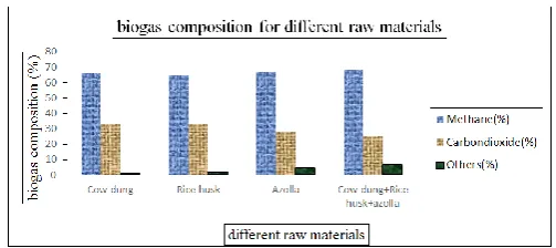
Cow dung 66 33 1
Rice husk 64.97 33 2.03
Azolla 67.27 28 4.76
Cow dung+ Rice husk+azolla 68.21 25.22 6.57
Page 376 www.ijiras.com | Email: contact@ijiras.com Figure 4.2: Biogas compositions for different raw materials
The compositional analysis carried out on the gas produced from each substrate. The percentage of methane and carbon dioxide were shown on figure and it shows that the highest methane content for mixing the raw materials. So the gas produced from the various mixtures has to be taken for analyzing the IC engines.
V. PERFORMANCE TEST BY PETROL A. TVS STAR CITY ENGINE SPECIFICATION
Here for doing the performance test - TVS star city bike engine has been chosen
Specification
Displacement 99.70 cubic centimeter Engine type Single cylinder four stroke
Power 5.50 HP (4 KW) @ 7500 rpm
Torque 7.50 NM
Compression 9:2:1
Fuel system Carburetor
Fuel control OHC
Cooling system Air
Gearbox 4-speed
Transmission final drive Chain
Clutch Wet, Multiplate
B. PERFORMANCE TEST ON PETROL ENGINE USING PETROL
a. APPARATUS USED
The star city engine was fitted with bed assembly and then the load test was carried out. The load was given by means of spring balance. The total fuel consumption was calculated by the help of burette reading of 10cc.
b. PERFORMANCE TEST WORKING PROCEDURE
Start the engine, put the engine in forth gear
Maintain the speed of the engine at 500 rpm by using the accelerator
At various load condition measure the time taken for 10cc of petrol in burette
The emission has been tested with the help of gas analyzer
Similarly the engine has been tested for various load conditions at the constant speed of 500 rpm,
Noted readings are then used for calculations.
c. PERFORMANCE TEST OBSERVATION-PETROL
It is concerned that all the readings were taken for constant speed method.
Load in %
Load
Speed Time for 10cc S1 S2 S1~S2
Kg Rpm S
0 0 0 0 500 104.3
25 7 5 2 500 95.6
50 12 7 5 500 90.1
75 17 9 8 500 81.3
Table 5.2: Performance test observation by petrol
d. FORMULAE USED
Load (W)
= (S1~S2)*9.81 N
TORQUE (T) = W*R Nm
Where R is the radius of the brake drum BRAKE POWER (BP)
= WATTS
Where N is the speed of the engine in rpm INDICATED POWER (IP) = B.P+ F.P
F.P can be Calculated by means of drawing the graph between B.P vs. TFC
TOTAL FUEL CONSUMPTION (TFC) =
kg/sec
INDICATED THERMAL EFFICIENCY
(ηIT) = %
BRAKE THERMAL EFFICIENCY
(ηBT = %
MECHANICAL EFFICIENCY
(ηMECH) = %
SPECIFIC FUEL CONSUMPTION(SFC) = kg/Wsec
e. PERFORMANCE CALCULATION-PETROL
%
Load
Tor
q
u
e
S
p
e
e
d Time
for 10cc
TFC BP FP IP ηI
T
ηB T
ηM EC H
SFC
S1 S2
S1
~ S2
Kg Nm
R p m
S Kg/s W W W % % %
Kg/ Ws
0 0 0 0 0 50
0 104.3 7.02*
10-5 0 3
5 35 10
.3 0 0 -
25 7 5 2 0.981 500 95.6 7.66*10-5 51.3
6 3 5
86. 36
23 .4
15 .2 0
59 .5 0
1.49* 10-6
50 12 7 5 2.45
25 50
0 90.1 8.13*
10-5 128.
41 3 5
163 .41
41 .8 0
32 .9 0
78 .5 8
6.33* 10-7
75 17 9 8 3.924 500 81.3 9.02*10-5 205.46 35 240.46
55 .5 0
47 .4 0
85 .4 4
4.39* 10-7
Page 377 www.ijiras.com | Email: contact@ijiras.com f. EMISSION TEST- PETROL
Emission Test- Petrol
LOAD
(%) O2 (%) CO (%)
NO2
(%) SO2 (%)
0 10.9 5.546 35 8
25 6.7 8.649 0 0
50 5.8 14.269 0 8
75 9.3 9.144 0 2537
Table 5.4: Emission Test- Petrol
VI. PERFORMANCE TEST BY BIOGAS A. PERFORMANCE TEST PROCEDURE
Similar to the performance test on petrol engine by petrol here also the same set of readings were taken
But in this case of bio gas, LPG gas kit was fitted with the engine
By tuning the carburetor and kit the running condition of the engine has been done
The measuring method for flow of the biogas was entirely differing from the petrol because here the electronic weighing machine was used to find out the total fuel consumption.
B. PERFORMANCES TEST OBSERVATION-BIOGAS Similar to that of the petrol test here same load and same speeds were maintained:
%
Load
Speed TFC S1 S2 S1~s2
Kg Rpm Kg/S
0 0 0 0 500 6.9*10-5
25 7 5 2 500 7.5*10-5
50 12 7 5 500 7.91*10-5
75 17 9 8 500 8.47*10-5
Table 6.1: Performance test observation by biogas
a. PERFORMANCE CALCULATION-BIO GAS
Calorific Value of the Biogas Using Azolla = 55MJ/Kg
% Load
Torque Speed TFC BP FP IP ηIT ηBT ηMECH SFC
S1 S2
S1
~ S2
Kg Nm Rpm Kg/s W W W % % % Kg/ws
0 0 0 0 0 500 6.9*10-5
0 25 25 6.58 0 0 -
25 7 5 2 0.981 500 7.5*10-5
51.38 25 76.38 18.5 12.46 67.27 1.45*10
-6
50 12 7 5 2.4525 500 7.91*10-5
128.46 25 153.46 35.3 29.55 83.70 6.15*10
-8
75 17 9 8 3.924 500 8.47*10-5
205.54 25 230.54 49.5 44.12 89.15 4.12*10
-7
Table 6.2: performance calculation table for biogas
C. EMISSION TEST- BIOGAS
Load (%) BIO GAS
Pollutants %(or)ppm
0 O2 CO X Air PI NO NO2 NOX SO2
CXHY
15.4 0.807 285 0 12 0 12 5817 35 25 O2 CO X Air PI NO NO2 NOX SO2
CXHY
17.2 1.047 472 0 7 0 7 4946 31
Load (%) Petrol
Pollutants % (or) ppm
0 O2 CO X Air PI NONO2 NOX SO2
CXHY
10.9 5.546 110 0.00 35 0 35 0 8 25 O2 CO X Air PI NO NO2 NOX SO2
CXHY
6.7 8.649 48 0 35 0 35 0 153 50 O2 CO X Air PI NO NO2 NOX SO2
CXHY
5.8 14.269 38 0 38 0 38 8 168 75 O2 CO X Air PI NO NO2 NOX SO2
CXHY
Page 378 www.ijiras.com | Email: contact@ijiras.com 50 O2 CO X Air PI NO NO2 NOX SO2
CXHY
20.4 0.273 20 0 1 0 1 1391 -32760 75 O2 CO X Air PI NO NO2 NOX SO2
CXHY
14.9 1.632 253 0 7 0 7 9617 31 Table 6.3: Emission test-biogas
VII. PETROL vs. BIOGAS
A. COMPARISON OF THE PERFORMANCE OF SI ENGINE
Table 7.1: Comparison of the performance of SI engine
a. BRAKE POWER VS. MECHANICAL EFFICIENCY
Figure 7.1: BP VS MECH EFFICIENCY
b. Brake Power vs. Indicated Thermal Efficiency
Figure 7.2: BP VS IT EFFICIENCY
c. BRAKE POWER VS. BRAKE THERMAL
EFFICIENCY
Figure 7.3: BP VS BT EFFICIENCY
d. BRAKE POWER VS. SFC
Figure 7.4: BP VS SFC
B. COMPARISONS OF EMISSION POLLUTANTS
LOAD (%) PETROL BIO GAS
Pollutants %(or)ppm Pollutants %(or)ppm
0 O2 CO XAIR PI NO NO2 NOX SO2
CXHY
10.9 5.546 110 0.00 35 0 35 0 8 O2 CO XAIR PI NO NO2 NOX SO2 CXHY 15.4 0.807 285 0 12 0 12 5817 35 25 O2 CO XAIR PI NO NO2 NOX SO2
CXHY
6.7 8.649 48 0 35 0 35 0 153 O2 CO XAIR PI NO NO2 NOX SO2 CXHY 17.2 1.047 472 0 7 0 7 4946 31 50 O2 CO XAIR PI NO NO2 NOX SO2
CXHY
5.8 14.26 38 0 38 0 38 8 168 O2 CO XAIR PI NO NO2 NOX SO2 CXHY 20.4 0.273 20 0 1 0 1 1391 32760 75 O2 CO XAIR PI NO NO2 NOX SO2
CXHY
9.3 9.144 81 0 51 0 51 2537 145 O2 CO XAIR PI NO NO2 NOX SO2 CXHY 14.9 1.632 253 0 7 0 7 9617 31 Load (%)
Petrol Biogas
ηIT ηBT ηMECH ηIT ηBT ηMECH
% % % % % %
0 10.3 0 0 6.58 0 0
25 23.4 15.20 59.50 18.5 12.46 67.27
50 41.80 32.90 78.58 39.3 29.55 83.70
Page 379 www.ijiras.com | Email: contact@ijiras.com
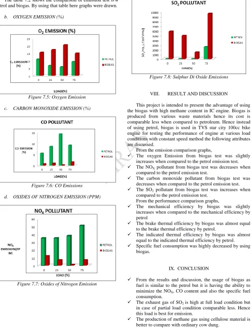
a. EMISSION TEST GRAPHS – COMPARISON
The table 7.2 shows the comparison of emission test b/w petrol and biogas. By using that table here graphs were drawn.
b. OXYGEN EMISSION (%)
Figure 7.5: Oxygen Emission
c. CARBON MONOXIDE EMISSION (%)
Figure 7.6: CO Emissions
d. OXIDES OF NITROGEN EMISSION (PPM)
Figure 7.7: Oxides of Nitrogen Emission
e. SULPHUR DI OXIDE EMISSION (PPM)
Figure 7.8: Sulphur Di Oxide Emissions
VIII. RESULT AND DISCUSSION
This project is intended to present the advantage of using the biogas with high methane content in IC engine. Biogas is produced from various waste materials hence its cost is comparable less when compared to petroleum. Hence instead of using petrol, biogas is used in TVS star city 100cc bike engine for testing the performance of engine at various load conditions with constant speed method the following attributes are discussed.
From the emission comparison graphs,
The oxygen Emission from biogas test was slightly increases when compared to the petrol emission test. The NOX pollutant from biogas test was decreases when
compared to the petrol emission test.
The carbon monoxide pollutant from biogas test was decreases when compared to the petrol emission test. The SO2 pollutant from biogas test was increases when
compared to the petrol emission test. From the performance comparison graphs,
The mechanical efficiency by biogas was slightly increases when compared to the mechanical efficiency by petrol
The brake thermal efficiency by biogas was almost equal to the brake thermal efficiency by petrol.
The indicated thermal efficiency by biogas was almost equal to the indicated thermal efficiency by petrol. Specific fuel consumption was highly decreased by using
biogas.
IX. CONCLUSION
From the results and discussion, the usage of biogas as fuel is similar to the petrol but it is having the ability to minimize the NOX, CO content and also the specific fuel consumption.
The exhaust gas of SO2 is high at full load condition but in case of partial load condition comparable less. Hence this load is best for emission.
Page 380 www.ijiras.com | Email: contact@ijiras.com Mixing of various raw materials also affect the biogas as
well as it increase the methane content so carefully choosen the raw materials.
Biogas is odorless hence; there is no fear for safety. Using biogas as a fuel for producing power, the problem
of electricity demand in our country can be resolved.
PHOTOGRAPHY
Figure 13.1: Biogas Plant
Figure 13.2: Azolla Caroliniana
Figure 13.3: Load test bed assembly
REFERENCES
[1] Al-Masri M.R, (2001) ‗Changes in biogas production due to different ratios of some animal and agricultural wastes‘. Bio resource Technology VOL.77, PP. 97-100. [2] Bade Shrestha S.O, and Karim G.A, (2001) ‗Predicting the effects of the presence of diluents with methane on
spark ignition engine performance.’ Applied Thermal Engineering vol.21, pp.331-342.
[3] Chandra.R, Vijay.V.K, Subbarao.P.M.V, Khura.T.K (2011) ‗Performance evaluation of a constant speed IC engine on CNG, methane enriched biogas and biogas‘. Applied energy vol.88, pp.3969-3977.
[4] Dipu.S, Kumar Anju.A and SalomGnanaThanga .V (2011), ‗Potential Application of Macrophytes Used in Phytoremediation‘. World Applied Sciences Journal vol.13 (3), pp.482-486.
[5] Emiliano Bruni, Anders Peter Jensen, Erik SilkjærPedersen, IriniAngelidaki (2010) ‗Anaerobic digestion of maize focusing on variety, harvest time and pretreatment‘. Applied Energy vol.87, pp. 2212–2217. [6] Kapdi.S.S, VijayV.K., Rajesh.S.K, Rajendra Prasad
(2005) ‗Biogas scrubbing, compression and storage: perspective and prospectus in Indian context‘. Renewable Energy vol.30, pp.1195–1202.
[7] Porpatham.E, A. Ramesh, B. Nagalingam (2012) ‗Effect of compression ratio on the performance and combustion of a biogas fuelled spark ignition engine‘. Fuel, vol. 95, pp. 247–256.
[8] Salih SÖZER and Osman YALDIZ, (2011) ‗Methane production from tomatoes wastes via co-fermentation‘. [9] Subramanian.K.A, Vinaya C. Mathad, Vijay.V.K,
Subbarao P.M.V. (2013), ‗Comparative evaluation of emission and fuel economy of an automotive spark ignition vehicle fuelled with methane enriched biogas and CNG using chassis dynamometer‘. Applied Energy vol. 105, 17–29.
[10] Thomas Amon, BarbaraAmon, VitaliyKryvoruchko, Werner Zollitsch, Karl Mayer, Leonhard Gruber (2007) ‗Biogas production from maize and dairy cattle manure— Influence of biomass composition on the methane yield‘. Agriculture, Ecosystems and Environment vol.118, pp. 173–182.
[11] WaseemRaja, PreetiRathaur, Suchit A John, Pramood W Ramteke (2012) ‗Azolla: an aquatic pteridophyte with great potential‘. International Journal of Research in Biological Sciences vol.2 (2), pp.68-72.
[12] Wei Qiao, Xiuyi Yan, Junhui Ye, YifeiSun, Wei Wang, Zhongzhi Zhang (2011) ‗Evaluation of biogas production from different biomass wastes with/without hydrothermal pretreatment‘. Renewable Energy, vol. 36, pp. 3313-3318. [13] Wendy Mussoline, Giovanni Esposito, Piet Lens, Alessandro Spagni, Andrea Giordano.(2013)‗Enhanced methane production from rice straw co-digested with anaerobic sludge from pulp and paper mill treatment process‘. Bioresource Technology, vol.148, pp.135–143. [14] Teodorita Al Seadi, Dominik Rutz, Heinz Prassl, Michael