Published online February 13, 2015 (http://www.sciencepublishinggroup.com/j/sr) doi: 10.11648/j.sr.20150301.15
ISSN: 2329-0935 (Print); ISSN: 2329-0927 (Online)
Optimum design and simulation of structure parameters of
pantograph based on equivalent mass
Zhang Shufeng
1, Yang Jian
1, Song Ruigang
1, Yuan Tianchen
21
College of Automobile Engineering, Shanghai University of Engineering Science, Shanghai, China
2
Institute of Mechanics, Shanghai University, Shanghai, China
Email address:
[email protected] (Zhang Shufeng), [email protected] (Yang Jian)
To cite this article:
Zhang Shufeng, Yang Jian, Song Ruigang, Yuan Tianchen. Optimum Design and Simulation of Structure Parameters of Pantograph Based on Equivalent Mass. Science Research. Vol. 3, No. 1, 2015, pp. 25-29. doi: 10.11648/j.sr.20150301.15
Abstract:
Based on the mathematical model of geometric relations of high-speed single-arm pantograph, structure parameters of the high-speed single-arm pantograph are optimized and designed applying multi-objective Optimization technology. Considering good contact of pantograph-catenary, rising height of pantograph and time of rising and dropping pantograph as the constraint condition, and considering the trajectory of pantograph head and the equivalent mass of pantograph as the target, a group of optimal structural parameters are gained combining with MATLAB software. The three-dimensional modeling of pantograph is completed according to the results of optimization. Applying virtual prototype technology to simulated analysis can verify the precision of the optimization results and methods.Keywords:
Pantograph, Equivalent Mass, Multi-objective Optimization, Virtual Prototype Technology1. Introduction
Previously, many scholars have researched the optimization of the structural parameters of pantograph. Be aimed at the torque of rising pantograph, the arm of force and the translation of pantograph’s head, The CSRGC has optimized the structure parameters of pantograph. The result of research as follow: the rising trajectory of pantograph’s head has a 27mm deviation in the driving direction[1,2]. The offset which is between the rising trajectory of pantograph’s head and the ideal vertical trajectory is as far as possible little at the time of designing the single-arm pantograph. So the single-arm pantograph is required as the double-arm pantograph. The equivalent mass of pantograph is one of the main parameters in the design of pantograph. The equivalent mass of pantograph refers to the actual quality of the whole activities section of pantograph (e.g., skateboarding, bracket, framework, etc.) is calculated to the contact point of pantograph-catenary, which makes the whole pantograph has the quality with the same acceleration of the pantograph slide. The equivalent mass of pantograph not only affects the current collection performance of pantograph, but it is main influencing factor for the following features of pantograph [3,4].
Based on a high-speed single-arm pantograph as an example, by the equivalent mass of pantograph as the
optimization target, and the main, combining the multi-objective optimization technology and the virtual prototype technology optimizes the structural parameters of pantograph so that get a better current collection performance.
2. Mathematical Model of Pantograph’s
Geometrical Relationship
2.1. Mathematical Model and Design Variable
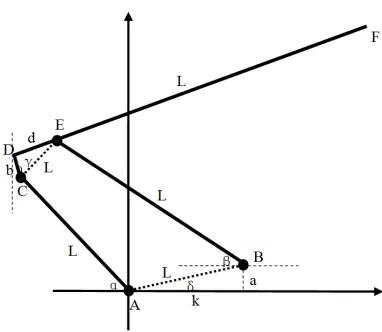
As shown in Figure 1. for geometry relationship diagram of single-arm pantograph’s movement component, the essence of which is a complex structure of four-bar linkage. The BE of figure is lower arm, which is the active rod and its angle is â. The AC is follower lever, its angle is á. Upper arm rod CDF directly contact with the head of pantograph. The è that is between CD rod and vertical direction can be indirectly shown the height of pantograph’s head. With the increase of è, the height of pantograph’s head can increases.
As shown in Table 1. for optimization variables and their meanings, the variable name derives from Figure 1. The optimization of pantograph’s structural parameters is to seek the best combination of these design variables so that the pantograph’s performance more superior.
Table 1. Design variables and meaning.
a The vertical distance of AB b The length of the CD d The length of the DE
k The longitudinal distance of AB
ã The angle of the upper and lower on the frame L1-5 The length of the AB/AC/DF/BE/CE
2.2. Analysis and Research of Mathematical Model
As shown in Figure 1., the A point is taken as the origin of coordinates, and the horizontal and vertical are taken as X and Y axes respectively. Based on the geometric diagram, using the geometry and plane four-bar linkage principle can gets the following relations.
(1) F point trajectory equation:
(1)
(2) Institutions geometric relationships:
(2)
(3) The speed relations between these links:
According to plane four-bar linkage principle, the length of each link can be confirmed approximately, whose result is L4>L2>L1>L5. Combining the figure of four-bar linkage and
the instantaneous center method can obtain speed relation of the each link[5,6]. If the speed of lower arm BE is W4, through
drawing the speed of pull arm AC and upper arm rod CDF can be calculated. The formula is as follows:
(3)
(4)
Among, the W2 is the speed of pull arm AC, and the W3 is
the speed of upper arm rod CDF. The ä is angle that is between ligature of fixed hinge bracket and X axis, and the ø is angle that is between link CD and link CE.
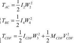
(4) Equivalent Mass Calculation:
The equivalent mass of pantograph refers to the actual quality of the whole activities section of pantograph (e.g., skateboarding, bracket, framework, etc.) is calculated to the contact point of pantograph-catenary, which makes the whole pantograph has the quality with the same acceleration of the pantograph slide. Kinetic energy formula of pantograph components is as follows:
(5)
Among, the I2 is the rotational inertia of pull arm AC, and
the I4 is the rotational inertia of lower arm BE. The ICDF is the
rotational inertia of upper arm rod CDF, and the VCDF is the
speed of upper arm rod CDF, and the MCDF is the total mass of
upper arm rod CDF[7,8]. Based on the definition of
equivalent mass, the formula of equivalent mass is as follows:
2
2
F energy kinetic mass equivalent CDF BE AC energy kineticV
T
M
T
T
T
T
− − −=
+
+
=
(6)Because the F point trajectory has already been calculated, the speed of the point F can be obtained by trajectory equation derivation, formula is:
2 2 2 2
2 2 4 4 3
2 2
( )
CDF CDF CDF equivalent mass
I W I W I W M V
M
X Y
−
+ + +
=
′ + ′ (7)
3. Geometrical Parameters Optimization
of Pantograph
3.1. Constraint Conditions and Optimization Targets of Mathematical Model
3.1.1. The Constraint Conditions
In order to ensure the good running of high-speed pantograph, it must satisfy many requirements in the process of work.
(1) The biggest rise height of pantograph’s head is about 3000mm.
(2) The working range of pantograph’s head is 360~2600mm.
3 2
3 2
sin( 90) cos( ) sin( )
cos( 90) sin( ) cos( )
y L b L
x L b L
= + − + + = + − − − γθ θ α γθ θ α 4 2 2 4
sin( ) sin( 90) cos( ) sin( )
sin( ) cos( ) cos( 90) cos( )
L a d b L
k b L d L
+ = + − + +
+ + = + − +
β γ θ θ α
θ α γθ β
2 2 1 1
2 4
2 2
cos(α) tan(90 θ-ψ) sin(α) cos(δ) tan(90 θ-ψ) sin(δ)
cos(α) tan(90 θ-ψ) sin(α)
L L L L
W W L L + + + + − = + + 4 4 3 4 4 4
tan(α) cos(β) tan(α) sin(β)
cos(β) tan(α)- sin(β)
a k L L
W W L L + − + = 2 2 2 2 4 4 2 2 3 1 2 1 2 1 1 2 2 AC BE
CDF CDF CDF CDF
T I W
T I W
T I W M V
(3) The fall height of pantograph is 280mm.
(4) The direction of pantograph’s head movement is ensured as far as possible to do vertical movement in the process of rising and falling pantograph. So the trajectory of pantograph’s head is a vertical straight line, and the permissible deviations must be less than 30mm within the scope of work.
(5) The time of rising pantograph is controlled within 6~10s, and the time of falling pantograph is less than 6s.
(6) In the process of the interaction between pantograph and catenary, the excellent following performance of pantograph is required, so that the equivalent mass of pantograph should be as small as possible. Within the scope of the normal stiffness and strength, equivalent mass should be the least.
(7) When the pantograph’s head in the highest position, the angle of rising pantograph is controlled within the range of 45~60
(8) From stability and operability, the relationship of each link is L4 > L2 and L1 > L5.
The fourth among the above requirement is the optimization goal of pantograph’s head trajectory, and the sixth is the optimization target of equivalent mass, and others are constraint conditions. From the previous formula, the trajectories of rising pantograph and equivalent mass are
decided by the design variables. So this is a multi-objective optimization problem [9,10].
3.1.2. The Objective Function
Multi-objective optimization problem has lots of solutions. The paper involves two optimization objectives, including trajectory is a vertical straight line. The x of trajectory equation is set as constant, as a constraint condition. This multi-objective problem is transformed into single objective problem, namely, under the same condition, how the parameters of the composite can make smaller reduction quality.
The x abscissa of point F is fixed value N, namely a formula:
(8)
The formula of angle is used as constraint conditions, and the value N is used as design variables.
According to the geometric relations of four bar linkage, the inertia formula of moment and the above a series of constraint conditions, further calculation analysis pantograph equivalent mass optimization objective function is:
2 2 2 2 2 2
2 2 2 4 4 4 3 3
2
3 3 3 3 3 2 2 2
3 3
3[ sin(γ ) sin( ) cos( )]
CDF CDF equivalent mass
M L W M L W I W M V
M
W L W t bW W t W L W t
− = + + +
+ − + (9)
Among, M2, M4 and M3, respectively is the quality of the
pull arm AC, lower arm BE and upper arm rod CDF.
3.2. MATLAB Optimization Method
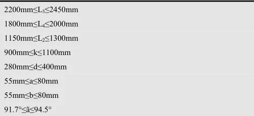
According to the constraint conditions, each design variable is geometric parameters of planar mechanism, so it must meets the requirements of planar mechanism freedom movement and at the same time the basic requirements of pantograph work. Scope of every design variable which can be concluded as follows:
Table 2. The range of design variable values.
2200mm≤L3≤2450mm
1800mm≤L4≤2000mm
1150mm≤L2≤1300mm
900mm≤k≤1100mm 280mm≤d≤400mm 55mm≤a≤80mm 55mm≤b≤80mm 91.7°≤ã≤94.5°
This article is from the pantograph structure parameters to study the equivalent mass, so the formula of equivalent mass can be further simplified as:
(10)
In order to further obtain the optimal value of equivalent mass, combined with the budget law, again from the impact factors to consider, get the following formula:
(11)
Combined with operation boundary condition, according to the above mathematical model, applying the optimization
toolbox of MATLAB language programming, the
optimization results are worked out. In which large values: d, L4, L2, ã, smaller values: a, b, k, L3. Using MATLAB to
further explore can obtain a set of optimal combination[11].
4. Optimization Results Simulation
Verification
Pantograph dynamic model is built with ADAMS software, and the optimal solution is inputted to proceed dynamic simulation [12,13]. Optimization design requirement for pantograph limit height is 3000mm and the time of rising pantograph controls within 6s. The following is the simulation image of rising pantograph’s height. (Note: the
3 2
3
2
cos( 90) sin( ) cos( )
cos( 90) sin( )
cos( )
x L b L N
L b N
L
= + − − − =
+ − − −
=
γ θ θ α
γ θ θ
α
2 2 2 2 2 2 * 2 2 4 4 3
2 3 3 3 3 3 2 2 2
3 3
3[ sin(γ ) sin( ) cos( )]
CDF CDF
L W L W I W V
M
W L W t bW W t W L W t
+ + +
=
+ − +
2 2 ** 2 2 1 4
2 2 2 2 4 4 2
2 2 2
3 3 2 4 4
( cos( ) ) sin ( ) cos ( )
[( ) ( ) ][ tan( ) sin( )]
F
L W t L L Q
M
L W t W t V
Q L b L b d a k W t L W t
+ + +
=
simulation, the falling pantograph position in -800mm)
Figure 2. Rising height of pantograph.
The simulation image of rising pantograph’s trajectory is as follows. (Note: falling pantograph, pantograph’s head level in 2176mm)
Figure 3. Rising deviation of pantograph.
Among them, the X-axis represents the running time of pantograph’s head, and Y-axis represents the running trajectory of pantograph’s head in the direction of the locomotive. By simulation image, the running trajectory of pantograph’s head is not a straight line. Ymin=2175mm,
Ymax=2200mm, Ymax-Ymin=25mm. So in normal
condition of pantograph, the trajectory deviation on the locomotive running direction is 25 mm < 30 mm, which conform to the requirements of the optimization design. Below image is curve relationship which is the running trajectory of pantograph’s head in the direction of the locomotive and rising pantograph’s height.
The figure shows that within the scope of the 25mm deviation, pantograph working range can be nearly 2500mm. For the present scope of pantograph’s work, this is satisfactory.
Figure 4. Trajectory of pantograph.
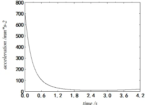
The equivalent mass do not direct simulate in the simulation software, so the pantograph’s vertical acceleration is used to indirectly reflect the following performance. Pantograph’s vertical acceleration simulation image is as follows.
Figure 5. Vertical acceleration of pantograph.
Among them, the X-axis represents the pantograph’s running time, and Y-axis represents pantograph’s vertical acceleration. From the simulation image, first acceleration is bigger, within 1s, the acceleration drops rapidly. Within the scope of work, the vertical acceleration almost remains at a smaller value. So this is satisfactory.
5. Conclusions
performance is well. To illustrate that the structural parameters of the optimization design was conform to the requirements, have certain research significance.
Acknowledgements
The paper is supported by innovation projects of postgraduate scientific research of Shanghai University of Engineering Science (number: A-0903-13-01129), the Twelfth Five-Year Program of Connotation Construction Project for Shanghai Local University (nhky-2014-07).
References
[1] Zhang Juan, Liu Zijian, Huang Daxiang, etc.. Low-speed single-arm pantograph structural parameters optimization design[J]. Mechanical Research & Application, 2004, 17(3):57-60.
[2] Chen Mingguo, Xu Xiaoqin, Li Jun, etc.. Optimum Design and Verification of Geometric Parameters for Single-arm Metro Pantograph Structure[J].Urban Mass Transit, 2009, 12(11):57-62.
[3] Li Fengliang, Sun Yan, Su Qian. TSG3 Pantograph’s Equivalent Mass[J]. Journal of Railway, 1998, 20(2):55-58. [4] Liu Zhaoyi. The modeling and simulation of
pantograph-catenary coupled system on high-speed railway[D]. Changsha: Central South University, 2012.
[5] Chen Xinbo, Lin Yan, etc.. Planar Four-bar Linkages With Double Crank Rotating The Driving Crank Two Turns in a Period of Motion[J]. Chinese Journal of Mechanical Engineering, 2003, 39(3):66-70.
[6] Jong-Hwi Seo, Seok-Won Kim, II-Ho Jung, et al. Dynamic analysis of a pantograph-catenary system using absolute nodal coordinates[J]. Vehicle System Dynamics 2006, 44(8): 615-630
[7] Li Fengliang, Li Min, Tang Jianxiang. Establishment of the pantographs mechanical models and measurement of their parameters [J]. Journal of Central South University (JCR-SCI), 2006, 37(1):194-199.
[8] Mei Guiming, Zhang Weiping. Dynamics model and behavior of pantograph/catenary system[J]. Journal of Traffic and Transportation Engineering, 2002, 2(1):20-25.
[9] Marian N. Velea, Per Wennhage, Dan Zenkert. Multi-objective optimization of vehicle bodies made of FRP sandwich structures[J]. Composite Structures, 2014, 111(5):75-84. [10] Marco Costa, Gian Marco Bianchi, Claudio Forte, et al. A
numerical methodology for the multi-objective optimization of the DI diesel engine combustion[J]. Energy Procedia, 2014, 45(1):711-720.
[11] Esmaile Khorram, Keshavarz Khaledian, Mehrdad Khaledyan. A numerical method for constructing the Pareto front of multi-objective optimization problems [J]. Journal of Computational and Applied Mathematics, 2014, (261): 158-171
[12] Jesus Peinado, Javier Ibnez, Ezack Arias, et al. Adams-bashforth and adams-moulton methods for solving differential Riccati equations[J]. Computers and Mathematics with Applications, 2010, 60(11):3032-3045.