Email address:
To cite this article:
Dalia Mohamed Sadek El-Gazzar, Said Abdel-Aleem Farag Hawash. Optimizing Centrifugal Pump Performance by Different Blade Configuration Patterns. American Journal of Mechanical and Industrial Engineering. Vol. 3, No. 1, 2018, pp. 1-14.
doi: 10.11648/j.ajmie.20180301.11
Received: January 9, 2018; Accepted: January 22, 2018; Published: February 23, 2018
Abstract:
Impeller blades configuration is directly affecting the performance of the pump. Using splitter blades are one of the techniques that used to improve hydraulic performance. These modifications in the blades design are greatly affecting the dynamic performance of the pump. Splitting the blade changes its center of mass and makes it out of alignment with the center of rotation leading to eccentricity problem. The present research elucidates the effect of changing the blades configurations on both of hydraulic and dynamic performances. The impeller under study was designed such that, its shape could be changed using the splitting technique. The conventional blade could be defined as a baseline reference. Moreover, three additional configurations resulted from splitting impeller blades is hydraulically and dynamically investigated. The changes in flow rates, heads, and vibrations associated with each case were recorded and compared with the conventional case. Therefore the main results were clearly indicated as, the highest value of the pump maximum efficiency recorded for 3rd configuration (as the middle and the outer parts staggered at 24° and 48° backward), where the lowest value for 1st configuration (as the inner part of the blade staggered at 24° forward). On the other hand, the results showed that, splitting the impeller blade's leads to uneven distribution of masses around the impeller thus leading to unbalance problem. Moreover, Vibration increased as the extent of blades locations deviations increased. Therefore, to avoid unbalance problem the splitting the impeller blades have to be in urgently and narrowest uses, such as to decrease cavitation occurrence, this may be the important recommendation.Keywords:
Blades Configuration, Splitting Technique, Hydraulic & Dynamic Performances, Eccentricity Problem1. Introduction
Centrifugal pumps are the most common type of kinetic pump and are used most often in applications with moderate-to-high flow and low head. A lot of research has been carried out to make it more efficient. Over the last
decades, many researchers have investigated the
centrifugal pump performance either experimentally or theoretically. Among these researches, the performance of the centrifugal pump has been studied by changing the impeller configurations; its blade shape, blade angles, adding splitters. In addition, the performance has been investigated for different operating conditions with these configurations change.
2. Literature Review and Its Outcomes
Atia E. Khalifa [1], mentioned that one way to reduce the effects of fluid interaction and pump vibration is to increase the effective gap by cutting the blade exit of the impeller. Different cut shapes are tested. Results showed the minimum pressure fluctuations inside the pump agree with the minimum pump vibration at the best efficiency point of the pump. Md. Abdul Saleem [2], used the deflected shape of shaft of a rotating machine for detecting unbalance in its rotating components. The change in deflection shape gives the presence of unbalance in the shaft. The results provided a new method for detecting machinery unbalance.
performance of the pump. As the splitter blade length increases; the flow rate and power increases, the efficiency decrease. As well as hydraulic performances are improved, pressure fluctuations are reduced. Kamlesh J. Vasava and Mital Patel [4], tried to give an idea about the previous researches & their finding about study of effect of splitter blades on the centrifugal pump performance. To increase the efficiency of centrifugal pump optimum value of number of blade is important. As the number of blade increases, the pump head rises but the too many blade results in a decrease in the efficiency. Zhang Jinfeng [5], studied the influence of adding splitter blades on the performance of the pump by using numerical method. The flow morphology shows that, when adding splitter blades to the impeller, the impeller
periphery velocities and pressures become more
homogeneous, which can reduce the pressure fluctuation at the area between impeller outlet and volute inlet. Pranit M. Patil [6], Ravi Teggin, and et. al [7], Abdellah A. moussa and Lin Yunhao [8] also, M. G. Patel and A. V. Doshi [9], discussed different techniques for improving centrifugal pump performance by changing impeller geometry. This improvement can be achieved by making geometrical changes in design of an impeller. From such literature, it has noticed that most of researches have investigated only the effect of the changing blade configuration on the hydraulic performance. Thus, there are no researches investigated this effect on the dynamic performance despite of its importance. This paper represents an integrated study of changing blade configuration and its effect on both the hydraulic and dynamic performances. Sami El-Shaikh, Mohamed Attia, and Abdullah Aboelnil [10] studied the Effect of different sizes of
shorted blade on pump performance theoretically. Three impeller configurations with different size shorted blade are installed. They also constructed a computational model to predict the performance parameters of centrifugal pumps and to analyze the flow field in the impellers’ passages. Computational results show a reduction in flow circulation for all shorted blades impeller comparing to standard impeller. Over the last decades, many researchers have investigated the centrifugal pump performance either experimentally (3, 4, 5, 6, 7 and 9), or theoretically (10). Among these researches (3, 4, 5, 6, 7 and 9), the performance of the centrifugal pump has been studied by changing the impeller configurations experimentally; its blade shape, blade angles, adding splitters. In addition, the performance has been investigated for different operating conditions with these configurations change.
3. Experimental Procedures
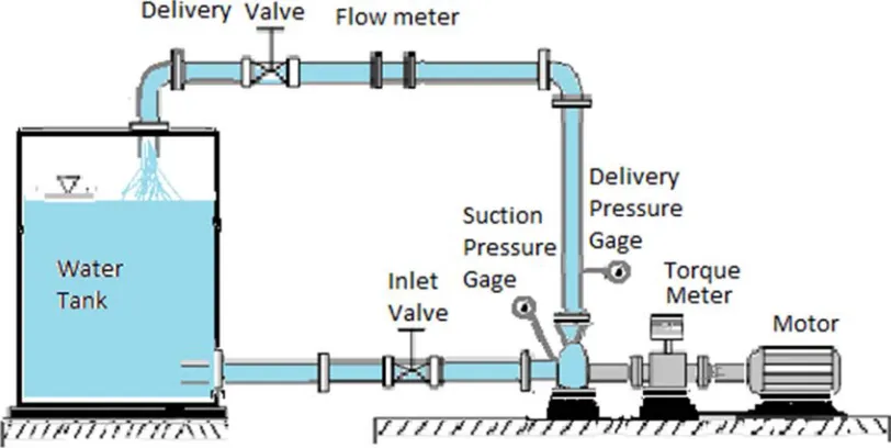
The experimental test rig consists of a centrifugal pump of design flow rate of 0.015 m3/s and head of 21 m running at 1450 rpm, derived by an electric motor of 10 HP (7.5 KW). Radial flow pump impeller, of 5 backward blades, has an outer diameter of 0.28 m and 0.1 m inner diameter. The pump is supplied from a tank of 5 m3 capacity. The test rig was set up to measure the pump head, discharge, power, and vibration. The change in flow rate and head associate with each blade configuration was recorded and compared to the conventional case. A schematic drawing of the experimental test rig arrangement is presented in Figure 1.
Figure 1. Experimental test rig arrangement.
4. Impeller Blade Calculations
Figure 2. Impeller inlet and outlet velocity diagrams, [11].
To check smooth blade shape, the change of the radial velocity components (
v
r1,v
r2) relative velocityv
1,v
2 are plotted against the corresponding radii as shown in Figure 2.4. Then, by using tangent arc method, the impeller is divided into four concentric rings between R1 and R2 Figure 3 Austin H. Church [25].Figure 3. Corresponding radii against radial & axial velocities.
Figure 4. Vane design using tangent arcs.
Therefore, the radius of the arc defining the vane shape between any two rings of radii R1 and R2 is given by:
Table 1. The radius of the arc defining the vane shape calculation.
Ring R R2 β Cos β R
2 Cos β2 R1Cos β1 (R22 – R12) ρ
1 5 25 17 0.956 4.78
1.869 24 6.421
2 7 49 18.2 0.9499 6.649
1.829 32 8.748
3 9 81 19.6 0.942 8.478
1.777 40 11.255
4 11 121 21.2 0.9323 10.255
2.534 75 14.799
5 14 196 24 0.9135 12.789
The average value of the vane angle
βm = [ (β1+ β2) / 2 ] (2)
βm = (17+24) / 2 = 20.50 degree.
The number of vanes
z
= { 6.5 sin β * [ (D2 + D1) / (D2 - D1) ] } (3)z
= 6.5 sin 20.5 * [ (28 + 10) / (28 - 10) ] = 4.8~
5 vanes.5. Impeller Design and Modifications
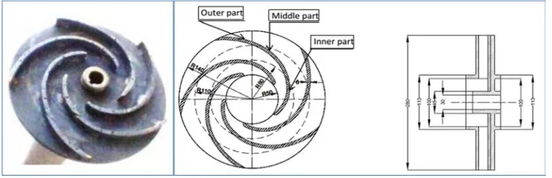
The impeller of the pump under investigation was designed such that, its shape could be changed. The impeller design is based upon a certain desired head and capacity at which the pump will operate most of the time. The impeller is a closed impeller manufactured with three blades. Each of the three blades was divided into three equal parts so that,
each part can be fixed separately. To give an opportunity to change the blade configuration, the second and the third portions of each blade could be rotated forward or backward by a step of 24°. The original case that has not any rotation (continuous blade) was tested as a base line reference or as the conventional blade. The original impeller configuration with its principal dimensions where the blades have their own curved flow path is shown in Figure 5.
Figure 5. Original impeller Configuration.
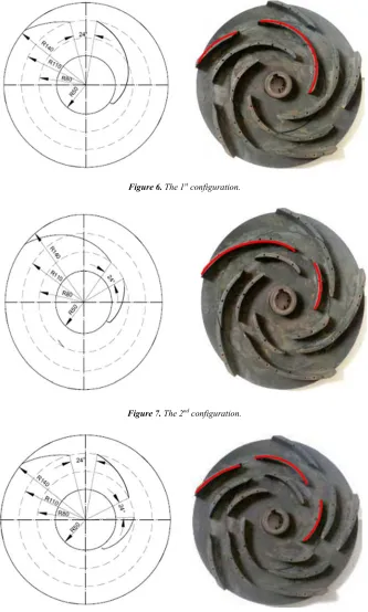
Moreover, Table 2 shows the staggered angle of the impeller blade parts, where conventional impeller (no blade parts rotate). On the other hand, impeller configuration is modified to introduce staggered arrangement with different configurations as shown in Figures 3, 4 and 5. Every blade is divided into three equal parts so that each part can be fixed separately and the shroud divided into 15 parts (at angle 24°) to give an opportunity to change the blade configuration into four stages. Impeller configuration is modified to introduce
staggered arrangement with different configurations. The first configuration was designed such that, the inner part of the blade staggered at 24° forward as shown in Figure 6. The second configuration was designed such that, the middle part of the blade staggered at 24° forward as shown in Figure 7. Also, the third configuration was as the middle and the outer parts staggered at 24° and 48o backward, respectively, as illustrated in Figure 8.
Table 2. . . . Rotation Angle of Impeller blades pats.
Relative angle of Rotation Configuration Inner Part Middle Part Outer Part
-24 0 +24 -24 0 +24 -48 -24 0 +24 +48
1st Configuration ▲ ▲ ▲
2nd Configuration ▲ ▲ ▲
Figure 6. The 1st configuration.
Figure 7. The 2nd configuration.
Figure 8. The 3rd configuration.
6. Hydraulic Investigation
The hydraulic investigation was evaluated for different blades configuration at impeller rotational speed n= 1450 rpm. Therefore, the main results show the effect of different configurations of the impeller blades on the pump performance at constant rotational speed (n=1450 rpm) are shown in Figures from 9 to 14.
6.1. Pump Performance Effected by Different Impeller Configurations at Constant Pump Speed
The evaluation of hydraulic and dynamic performances was performed by measuring the pump head, discharge, power, and vibration. Then these measurements were analyzed to indicate the effect of each impeller configuration. So, change in flow rate and head associate with each blade
configuration was recorded and compared to the
conventional case.
6.1.1. Effect of 1st Configuration on the Pump Performance
The experimental results of the pump performance for 1st configuration are shown in Figures 9 and 10. In these plots, the variations of the pump head and efficiency with the pump flow rates are illustrated. So, In Figure 9, the results showed that, the head for conventional impeller is higher than the head for 1st configuration. While in Figure 10, the
max. pump efficiency for conventional impeller
(ηmax)Conventional reaches 46.2%, so it is better than the max.
efficiency for 1st configuration (ηmax)First Config. which reaches
42.0%. Therefore, the increasing difference between these two cases is equal to 4.2%, which represents an increasing rate of about 9.10%. This decreasing of (ηmax)First Config. than
(ηmax)Conventional may be due to the decreasing of the pump
head for 1st configuration (20m ) than the head for conventional impeller (21.8m).
6.1.2. Effect of 2nd Configuration on the Pump Performance
The experimental results of the pump performance for 2nd configuration are shown in Figures 11 and 12. In these plots, the variations of the pump head and efficiency with the pump flow rates are illustrated. From Figure 11, the results showed
that, the head for conventional impeller is higher than the head for 2nd configuration. While, in Figure 12, the results showed that, the pump efficiency for conventional impeller is better than the efficiency for 2nd configuration.
6.1.3. Effect of 3rd Configuration on the Pump Performance
The experimental results of the pump performance for 3rd configuration are shown in Figures 13 and 14. The results showed that, the head for conventional impeller is higher than the head for 3rd configuration, as illustrated in Figure 13. While, in Figure 14, the pump efficiency for conventional impeller is better than the efficiency for 3rd configuration
6.1.4. Effect of All Configurations on the Pump Performance
The comparison results of the pump head and efficiency for all configurations are shown in Figures 15 and 16, respectively at pump rotational speed of n= 1450 rpm. The main results illustrated that the pump head and efficiency for conventional impeller is higher than the other blade configurations. Moreover, the best performance represented for 3rd configuration, while the worst Performance for 1st configuration.
6.1.5. The Conventional Configuration Compared with Other Different Ones
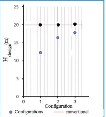
Moreover, it’s urgent to illustrate the variation of pump maximum efficiency, maximum design flowrate and design head at constant pump rotational speed (n=1450 rpm), for different blade configurations, see next Figures (17, 18 and 19).
Figure 10. ɳ-Q Curve for 1st configuration and conventional impeller at n= 1450 rpm.
Figure 11. H-Q Curve for 2nd configuration and and conventional impeller at n= 1450 rpm.
Figure 13. H-Q Curve for 3rd configuration and conventional impeller at n= 1450 rpm.
Figure 14. ɳ-Q Curve for 3rd configuration and conventional impeller at n= 1450 rpm.
Figure 16. Variations of the pump efficiency with the pump flowrates for different blade configurations at n = 1450rpm.
Figure 17. Variation of pump max. head for different blade configuration at n= 1450 rpm.
Figure 18. Variation of pump max. efficiency for different blade configuration at n= 1450 rpm.
Figure 19. Variation of pump design flowrate for different blade configuration at n= 1450 rpm.
6.2. Main Results of Hydraulic Investigation
Generally, when a centrifugal pump is to be tested, the main objective is to determine its characteristic curves at a desired rotational speed. These curves show the relation of the pump head and efficiency versus the pump discharge at constant impeller speed for different impeller configurations. So, the centrifugal pump was tested at constant rotational speed 1450rpm, then, the performance of different configurations, were compared with the conventional case, as shown previously in Figures, from 6 to 16. Therefore, The main hydraulic results could be stated as the following: First; Figure 14, shows the variation of the pump design head (head at ƞmax),
and constant rotational speed n=1450 rpm, for different blade configurations, which indicated that, the highest pump design head recorded for 3rd configuration and the lowest value for 1st configuration. Second; Figure 15, clearly indicates that, the highest value of the pump maximum efficiency recorded for 3rd configuration, and the lowest value for 1st configuration. Third; Figure 16, shows the variation of pump design flow rate Q for (ƞmax,), at constant rotational speed n=1450 rpm, for
different blade configurations, which indicated that, the highest value of the pump design flow rate at 1st configuration, and the lowest at 3rd configuration.
7. Dynamic Investigation
performed. Vibration signals were recorded during operating conditions and the data is analyzed using a signal analyzer. The instruments were used to acquire the vibration signals in terms of velocity at 9 locations including:
1. Motor non drive end bearing in axial direction 2. Motor non drive end bearing in vertical direction 3. Motor non drive end bearing in horizontal direction 4. Motor drive end bearing in axial direction
5. Motor drive end bearing in vertical direction 6. Motor drive end bearing in horizontal direction
7. Pump drive end in axial direction 8. Pump drive end in vertical direction 9. Pump drive end in horizontal direction
Measurement locations are shown in Figure 20. Frequency
spectra were obtained under different impeller
configurations. Overall vibration velocities were measured using FFT (Fast Fourier Transform) at the initial condition. These vibrational spectra can be used to determine excitation sources. All measurements were taken in axial, horizontal, and vertical directions.
Figure 20. Measurement locations on the pump unit.
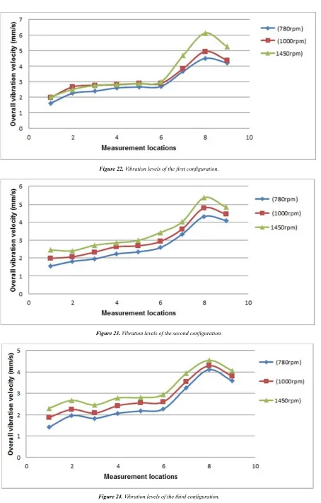
The three impeller configurations and conventional one were tested for vibration at three rotational speeds to indicate the effect of speed variation on each impeller configuration.
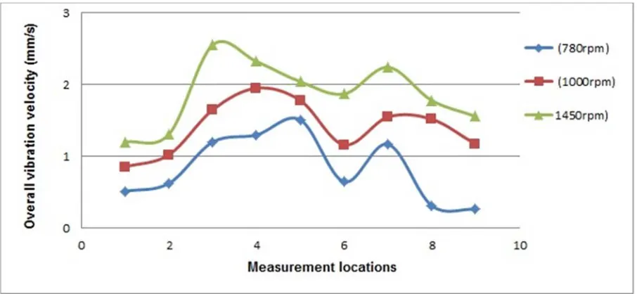
For the conventional impeller configuration, maximum overall vibration velocity reached 1.30 mm/s, 2.27 mm/s, and 2.55 mm/s at the three rotational speeds respectively as shown in Fig. 21. These levels are within the acceptable range of operation according to ISO 10816-3.
For the first impeller configuration, maximum overall vibration velocity reached 4.51 mm/s, 4.95 mm/s, and 5.62 mm/s at the three rotational speeds respectively as shown in Figure 22. According to ISO 10816 -3 these values exceed
the permissible level and fall within the danger region of operation.
For the second impeller configuration, maximum overall vibration velocity reached 4.32 mm/s, 4.80 mm/s, and 5.08 mm/s at the three rotational speeds respectively as shown in Figure 23. According to ISO 10816 -3 these values exceed the permissible level and fall within the danger region of operation.
For the third impeller configuration, maximum overall vibration velocity reached 4.11 mm/s, 4.30 mm/s, and 4.41 mm/s at the three rotational speeds respectively as shown in Figure 24. According to ISO 10816-3 these values exceed the permissible level and fall within the alarm region of operation.
Figure 22. Vibration levels of the first configuration.
Figure 23. Vibration levels of the second configuration.
For all four cases it could be seen that, as the speed increases, the amplitude is also increased. This increase in amplitude value is because of increase of centrifugal force. The overall vibration velocity at horizontal direction is higher than axial direction. To determine the cause of high vibrations and excitation forces, spectrum analysis was carried out. Following are the spectrums took at different speeds of the three impeller configurations. Observation from spectrum confirmed that in all spectrums 1X is present. The
vibration velocity is more obvious in the radial horizontal direction than axial direction. The vibration amplitude reached its higher value at the impeller location. Frequency analysis at the case of using the conventional impeller indicated that, vibrations on the motor and the pump within an acceptable range. Maximum vibration amplitude reached 1.94 mm/s. No faults are detected and the pump working normally at the three speeds as shown in Figure 25.
Figure 25. Vibration spectrum of the conventional configuration at 780 rpm, 1000 rpm, and 1450 rpm.
Frequency analysis at the case of using the first impeller configuration indicated that, there were high vibration amplitudes at 1X in the radial horizontal direction. Vibration levels are within acceptable range for 780 rpm and 1000 rpm. Maximum vibration amplitude reached 4.8 mm/s at 1450 rpm respectively as shown in Figure 26. This vibration level is unacceptable and not permissible. Frequency analysis at the
case of using the second impeller configuration indicated that, there were high vibration amplitudes at 1X in the radial horizontal direction. Vibration levels are within acceptable range for 780 rpm. Maximum vibration amplitude reached 4.8 mm/s and 4.77 mm/s at 1000 rpm and 1450 rpm respectively as shown in Figure 27. These vibration levels are unacceptable and not permissible
Figure 27. Vibration spectrum of the second configuration at 780 rpm, 1000 rpm, and 1450 rpm.
Frequency analysis at the case of using the third impeller configuration indicated that, there were high vibration amplitudes at 1X in the radial horizontal direction. Vibration levels are within acceptable range for 780 rpm and 1000 rpm.
Maximum vibration amplitude reached 4.24 mm/s at 1450 rpm respectively as shown in Figure 28. This vibration level is unacceptable and not permissible.
Figure 28. Vibration spectrum of the third configuration at 780 rpm, 1000 rpm, and 1450 rpm.
8. Main Results of the Dynamic
Investigation
All these results confirmed that there is a problem of unbalance exists in the impeller. High 1X amplitudes in horizontal and vertical spectrum indicates an abnormal condition of unbalance. Unbalance generates a radial force and produces a vibration frequency equal to shaft speed. This radial force causes the shaft to deflect, producing an axial direction vibration in the bearings. As amplitude increases with speed, an unbalance force is also increased at the
horizontal direction. Arising unbalanced distribution of rotating masses around the axis of rotation leads to arising of the rotor unbalance. The first impeller configuration recorded the worst case of dynamic performance while, the conventional configuration recorded the best one. Effect of unbalance was obvious at the locations of bearings so, increasing unbalanced forces can lead to damage of bearings and finally destruction of the machines.
9. Conclusion
performance. When an impeller has undistributed masses or geometrical manufacturing deviations, high vibration occurs from an unbalanced force rotating with the impeller generated from eccentricity. The main hydraulic results showed that, the head characteristic have shown almost the same trend. On the other hand, splitting the impeller blades impacts the hydraulic losses (friction losses and shock losses) differently depending on the number of offsets and the position and the direction of shift as follows; increasing the number of splitted parts decreases the friction losses due to decreasing in the effective length. However, it increases the shock losses due to multi entrance. The pump efficiency increases at splitting the blades into three parts and shifting forward, (3rd configuration) due to a decrease in hydraulic losses, then, pump cavitation is eliminated in case of splitting the blades into three parts in the middle (3rd configuration), and increases with other configuration. First impeller configuration recorded the worst dynamic performance while, conventional impeller configuration recorded the best one. The results of the experiments showed that the vibration increased as the increase of the extent of blades locations deviations.
References
[1] Atia E. Khalifa, “Effect of Blade Exit Shape on Performance and Vibration of a Double Volute Centrifugal Pump.” International Journal of Materials, Mechanics, and Manufacturing, Vol. 2, No. 4, November 2014.
[2] Md. Abdul Saleem, “Detection of Unbalance in Rotating Machines Using Shaft Deflection Measurement during Its Operation.”, IOSR Journal of Mechanical and Civil Engineering (IOSR-JMCE), ISSN: 2278-1684 Volume 3, Issue 3, PP 08-20, Sep-Oct. 2012.
[3] Pranit M. Patil and R. G. Todkar, “An Overview of Effect of Splitter Blades on Centrifugal Pump Performance.”, International Journal of Engineering Research & Technology, Vol. 2, Issue 11, ISSN 2278-0181, November 2013.
[4] Kamlesh J. Vasava and Mital Patel, “A General Review on Effect of Splitter Blade on the Performance of Centrifugal Pump.”, Afro-Asian International Conference on Science, Engineering & Technology, ISBN: 9-780993-909238, AAICSET, 2015.
[5] Zhang Jinfeng, “Influence Of Splitter Blades On The Total Flow Field of A Low-Specific Centrifugal Pump.” Technology and Research Center of Fluid Machinery Engineering, Jiangsu University, Zhenjiang, 2013.
[6] Pranit M. Patil, “Effect of Geometrical Changes of Impeller on Centrifugal Pump Performance.” International Research Journal of Engineering and Technology (IRJET), Volume: 02 Issue: 02, May, 2015.
[7] Ravi Teggin, Shashank M Hebbal, and M. S. Hebbal, “Effect of Blade Geometry on Hydraulic Performance of the Centrifugal pump.” International Journal of Innovative Research in Science, Engineering and Technology, ISSN (Online): 2319-8753, ISSN (Print): 2347-6710, Vol. 5, Issue 7, July, 2016.
[8] Abdellah Ait moussa and Lin Yunhao, “Improving the Hydraulic Efficiency of Centrifugal Pumps Through Computational Fluid Dynamics Based Design optimization.” Int. Journal of Engineering Research and Applications, ISSN: 2248-9622, Vol. 4, Issue 8 (Version1), pp. 158-165, August, 2014.
[9] M. G. Patel and A. V. Doshi, “Effect of Impeller Blade Exit Angle on the Performance of Centrifugal Pump.” International Journal of Emerging Technology and Advanced Engineering, Website: ww.ijetae.com, ISSN 2250-2459, Volume 3, Issue 1, January, 2013.
[10] Sami El-Shaikh, et al, ”Numerical Investigation of Short Blades Effect on the Performance of a Centrifugal Pump.” International Journal of Mechanical Engineering and Applications, pp: 186-193, ISSN: 2330-0248, 2017.
![Figure 2. Impeller inlet and outlet velocity diagrams, [11].](https://thumb-us.123doks.com/thumbv2/123dok_us/8571310.1716725/3.595.152.441.476.714/figure-impeller-inlet-outlet-velocity-diagrams.webp)