Microcontroller Application in Industrial Control & Monitoring Systems
Full text
Figure


Related documents
The primary endpoint was treatment effi cacy, with cure rate defi ned serologically as a decrease in rapid plasma reagin titre of at least two dilutions by 6 months after
It shall be possible to automatically inhibit the alarming of any analog input or
Está solamente por la presencia de la tierra que el fuego puede quemar (fuego en la tierra), agua puede ser aspirada de (agua en la tierra), los cuerpos puede
Use your hybrid map and the Biloxi index map to locate a photographic image that includes the intersection of Front Beach Drive and Martin Avenue in Ocean Springs, MS (note
In spring 2013, hazelnut leaves, fruit clusters and shoots showing powdery mildew infection symptoms different from those observed previously were discovered in Giresun, Ordu
Loss or damage to materials and components to be incorporated in the contract works whilst in storage away from the contract site for a period of up to 90 days, subsequent to
HARDWARE INPUTS – The MIXER PAGE also provides software level control for direct monitoring of the FireWire 410’s analog and S/PDIF digital inputs.. These pairs are labeled ANALOG
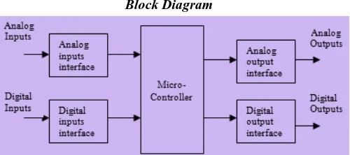
4 Relay Output Module 16 logic inputs Analog inputs External power supply USB link.. 8 Analog
