http://www.sciencepublishinggroup.com/j/com doi: 10.11648/j.com.20200801.12
ISSN: 2328-5966 (Print); ISSN: 2328-5923 (Online)
Implementation and Analysis of Signal Tracking Loops for
Software Defined GPS Receiver
Aye Su Su Phyo
1, Hla Myo Tun
1, Atar Mon
1, Sao Hone Pha
2 1Department of Electronic Engineering, Yangon Technological University Gyogone, Insein, Yangon, Myanmar 2Remote Sensing and GIS Research Center, Yangon Technological University Gyogone, Insein, Yangon, Myanmar
Email address:
To cite this article:
Aye Su Su Phyo, Hla Myo Tun, Atar Mon, Sao Hone Pha. Implementation and Analysis of Signal Tracking Loops for Software Defined GPS Receiver. Communications. Vol. 8, No. 1, 2020, pp. 9-16. doi: 10.11648/j.com.20200801.12
Received: November 11, 2019; Accepted: December 26, 2019; Published: January 7, 2020
Abstract:
Software defined GPS receiver has been developing because it can be processed advanced signal algorithms and also developed for precise navigation. Signal processing modules such as signal acquisition, signal tracking and navigation demodulation are implemented in software to estimate the receiver position, velocity and time (PVT). Signal tracking is important task in order to estimate the receiver’s and satellites position by demodulating navigation bits which are obtained from this. In this paper, implementation and analysis of signal tracking loop is mainly described and there are two main tracking loop as carrier and code tracking loop on GPS L1 signal. Delay Locked Loop (DLL) is to track code delay or code phase of GPS Coarse or Acquisition (C/A) code while Phase Locked Loop (PLL) is used to track GPS L1 carrier frequency as well as Doppler Frequency Shift. The implementation of DLL and PLL, and analyses of parameters which effects on navigation bits is also briefly discussed. The results confirm the analysis of signal tracking loops for software defined GPS receiver based on the experimental studies. The real time applications for software defined GPS receiver are very important to implement the navigation system in future because of the effective analyses on theoretical consideration.Keywords:
GPS, Software Defined Receiver, Signal Tracking Loop, DLL, PLL1. Introduction
GPS is Global Positioning Systemwhich provides positioning services to Military as well as Civil users. It was launched in 1973 by the United State (U.S) and fully operational in 1995. GPS comprises three main segments: space segment, control segment and user segment. Space segments includes satellite vehicles (SV) which operate about 20,200 km (12,550 miles)in MEO (Medium Earth Orbit). Control Segment is composed of ground stations to track and monitor satellites transmissions and send data commands to the constellation of them. User segment consists of antenna and receivers which provides user’s location coordinates and accurate time [1].
The user can estimate the position by the computation of the range between the receiver and satellites which called pseudoranges. The range between receiver and satellites is called pseudorange instead of a range because of clock bias between receiver’s clock and satellites’ clock. So the receiver
2. GPS Signal Tracking Loop
Figure 1 shows block diagram of GPS software receiver.
There are two tracking loop in GPS receiver: code tracking loop and carrier tracking loop.
Figure 1. Block Diagram of GPS Software Receiver. It is needed to keep track the two parameters obtained
from the acquisition stage: carrier (Doppler) frequencyand code phase since they changeover time. Therefore, code tracking loop’s task is to continually trackfor code phase and carrier tracking loop is for Doppler frequency shift. In order to obtain only navigation message from modulated signal, code demodulation and carrier demodulation must be performed. So, code removal can be performed by multiplying the C/A code of input signal with local C/A code replica and carrier is also removed by multiplying the carrier of input signal with local carrier wave. Figure 2 shows basic demodulation to obtain navigation data bits [2].
Figure 2. Demodulation Navigation Bits [5].
2.1. Delay Locked Loop (DLL)
Code tracking loop or Delay Locked Loop (DLL) is for tracking of code phase of the signal. The incoming satellite signal is divided into in-phase (I) and quadrature (Q) which is 90˚ phase shifted version of I. The local C/A code generates three codes: Early (E), Prompt (P) and Late (L) codes. The common spacing between each code is ± 0.5 and it determines the noise bandwidth in DLL. It also determines the dynamic range of the signal and accuracy in the positioning result. The, the outputs are integrated and are compared with discriminator to produce code error between the incoming GPS signal and local code. The code loop discriminator is an error function that depends on the two correlation functions, early and late [4]. There are different types of discriminator function and the analysis of the effect of using different early-late spacings, discriminators and noise bandwidth is discussed in the simulation results of this
paper.
2.2. Phase Locked Loop (PLL) or Costas Loop
To keep track of phase error between carrier of the incoming signal and local carrier wave, carrier tracking loop or PLL is implemented. In GPS, Costas loop is used instead of simple PLL because it can still keep track the phase shifted signal which is caused by the navigation transitions. As in DLL, the outputs of phase discriminator are filtered and estimate the phase offset and when the signal is in a phase locked condition, the prompt output of the in-phase arm produces the navigation data bits and quadrature arm is at steady state with a minimum amplitude. Figure 3 shows structure of the basic tracking loop. It contains filter and numerical controlled oscillator (NCO). The task of filter is to filter noise in the error measurements due to the noise in the tracked signal and NCO is a signal generator to generate replica of the tracked signal. Transfer functions of loop filter and NCO are described as in equations (1) and (2).
Figure 3. Basic Tracking Loop [2]. F s = τ2s+1
sτ1 (1)
N s =K1
s (2)
System transfer function is
H s = K2F s N(s) 1+K2F s N(s)=
2ζωns+ωn2 s2+2ζω
ns+ωn2 (3)
Figure 4. Second Order PLL [5].
Figure 4 shows second order PLL and digitized PLL by applying bilinear transform is as following equations (4) to (6).
s=2 ts
1-z-1
1+z-1 (4)
H z =
2τ2+ts 2τ1
-2τ2-ts 2τ1 z
-1
1-z-1 (5)
H z = a+b -bz-1
1-z-1 (6)
Therefore, two coefficients a and b are as in equations (7) and (8) respectively.
a=τ2 τ1
-ts
2τ1 (7)
b=ts
τ1 (8)
Transfer function of NCO is
N z =K1z
-1
1-z-1 (9)
ωn= 8ζBn
4ζ2+1 (10)
Table 1. Different types of non- coherent DLL discriminators.
Name Discriminators
Dot Product ∑IE-IL IP-∑QE-QL QP
Early-Late Power ∑IE2+ QE
2
-∑IL2+ QL 2
Early-Late Envelope ∑ IE2+ QE
2
-∑ IL2- QL
2
Early-Late Normalized Envelope ∑ IE
2+ Q E
2
-∑ IL2+ QL 2
IE2+ QE 2
+∑ IL2+ QL 2
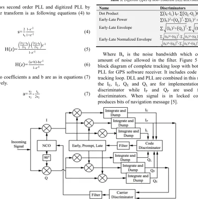
Where Bn is the noise bandwidth which controls the amount of noise allowed in the filter. Figure 5 shows the block diagram of complete tracking loop with both DLL and PLL for GPS software receiver. It includes code and carrier tracking loop. DLL and PLL are combined in this scheme and the IE, IL, QE and QL are for implementation of Code discriminator while IP and QP are used for carrier discriminators. When signal is in locked condition, IP produces bits of navigation message [5].
Figure 5. Complete GPS Tracking Loop.
3. Implementation of DLL and PLL
In Delay Locked Loop (DLL), firstly local C/A code is needed to three local codes with general ± ½ chips apart between each code to correlate with the C/A code of the incoming signal. The discriminator signal is
ε=E
L (11)
When = 1, the prompt code is perfectly aligned with the incoming C/A coded signal, no shift is necessary. < 1, a phase shift to the left has occurred, shift the codes to the
Table 2. Different Types of DLL Discriminators [6].
Type Discriminators
I Dot Product
II Early Minus Late Power
III Early Minus Late Envelope
IV Early Minus Late Envelope Normalized
In PLL, phase error can be minimized when correlation in the quadrature-phase arm is minimum and the correlation value in the in-phase arm is maximum. Table 3 shows different phase discriminator function and arctangent discriminator outputs the real phase error of the signal.
Table 3. Different Types of PLL Discriminators [2].
Discriminator Characteristics
D=sign(IK)(QK) The discriminator output is proportional to
sin ( ).
D=IKQK The discriminator output is proportional to sin (2 )
d=tan-1 Q
K
IK The discriminator output is the phase error (
4. Test and Results
4.1. Implementation for GPS Software Receiver
Figure 6 shows implementation of proposed GPS software receiver. The incoming GPS signal is obtained from GPS antenna and the front-end (RTL2832u) is used to down convert the RF signal into IF (Intermediate Frequency) signal in order to perform signal processing in laptop or PC using MATLAB programming language. The input signal from the frond-end is converted into complex I and Q signal. Figure 7 and 8 shows time domain and frequency domain of captured GPS L1 signals in the first 1000ms (1 sec).
Figure 6. Proposed Software Defined GPS Receiver.
Figure 7. Received GPS signal in time domain.
Figure 8. Received GPS signal in frequency domain.
Doppler frequency and code phase for each satellites (PRN) are listed in table 4. PRN 26, 23, 22 and 16 are four satellites in view in the signal captured time. Doppler frequency shift is described in Hz and Code phase value in chips (bits).
Table 4. Doppler Frequency and Code Phase of satellites.
RRN Doppler Frequency (Hz) Code Phase (chips)
26 938 290
23 -4156 684
22 -469 1799
16 -945 494
4.2. Implementation and Analysis of Code Tracking Loop (DLL) and Carrier Tracking Loop (PLL)
Code and carrier error of PRN 26 in 3700 ms (3.7 sec) are shown in Figures 9 and 10 respectively. For DLL, loop gain (k or K1K2) of 1, noise bandwidth (Bn) of 2 Hz, zeta ( ) of 0.7 and discriminator (Early-Late) spacing (ds) of 0.5 is chosen. For PLL, k of 0.25, Bn of 25 Hz, of 0.7 are chosen.
Figure 10. Carrier Error.
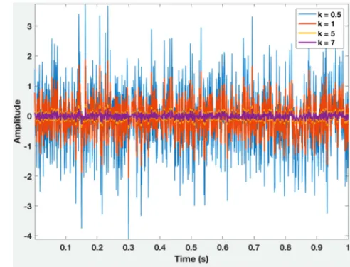
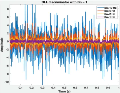
Changing different parameters such as discriminator functions, discriminator spacing, damping ratio and noise bandwidth on both DLL and PLL are discussed in this section. The effect of changing different correlator spacing values in code error is shown in Figure 11. Figures 12, 13 and 14 shows DLL outputs with different damping ratio, loop gain and noise bandwidth of 1000 ms of the resulted signal. Figure 15 shows DLL outputs with different discriminator functions which are described in Table 1.
Figure 11. Code Error with different Early-Late spacing.
Figure 14. Outputs of DLL with different Noise Bandwidth, Bn.
Firstly, three values of early-late spacing are tested. Among three values, small one reduces the code phase dynamic range and code error variance. Moreover, the larger value of becomes wider code phase compared to the other three lower values in testing with four different damping ratio. However, in contrast of damping ratio, lower value of loop gain k can make wider tracking dynamics. Loop noise bandwidth (Bn) controls the noise in the filter. So, larger value of bandwidth allows larger noise in the code tracking loop. In Figure 15, four different DLL discriminator functions are test and the results show that other discriminator functions has quite low code phase values than Early-Late Envelope Normalized function. So, it can produce more correct code phase values than the other functions and it is more suitable for implementation of DLL tracking loop.
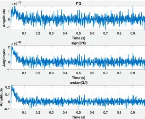
Figure 15. Outputs of DLL with different discriminator functions. Result of PLL outputs is also analyzed by changing
different parameters as in DLL. Figure 16 shows the outputs of PLL with different damping ratio . The greater the value of , the faster the settling time in carrier loop and the further with the carrier of incoming signal. In case of loop gain k which described in Figure 17, large values which are greater than 0.25 causes fast lock in PLL but small variations of carrier outputs. In contrast with loop gain, larger value of noise bandwidth Bn allows more variations of PLL outputs. In figure 18, Bn= 40 Hz causes large variations of PLL and that means it doesn’t provide correct converge in the incoming signal. Moreover, arctangent discriminator can provide correct PLL outputs among three PLL discriminator functions which are mentioned in Table 1 because its output is the real phase error and Figure 19 describes the results.
Figure 17. Outputs of PLL with different loop gain, k.
Figure 18. Outputs of PLL with different Noise Bandwidth, Bn.
Figure 19. Outputs of PLL with different Discriminator Functions.
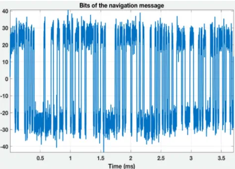
According to the results of the analysis of code and carrier tracking loop, the prior values of each parameters for both DLL and PLL are the best choice to provide the correct navigation data bits. Figure 20 to 23 shows the results of the navigation bits of four acquired satellites (PRN 26, 23, 22 and 16) listed in Table 4.
Figure 20. Navigation data bits of PRN 26.
Figure 21. Navigation data bits of PRN 23.
Figure 23. Navigation data bits of PRN 16.
5. Conclusion
This paper presents the implementation of code and carrier tracking loop with different values of each parameter and their effects. The input GPS signal is recorded from RF-front end (RTL2832u) and since the antenna is not in sky space, there are few satellites in the current captured signal. In acquisition results, four satellites (PRN 26,23,22 and 16) are acquired and all satellites have lower ±10 kHz which are maximum value of Doppler frequency caused by the motion between satellites and receiver. For the results of tracking loop, only PRN 26 is used to describe since the results are similar with each other. In an implementation of code and carrier tracking loop, outputs of DLL and PLL for 1000ms of the signal are described. The analysis of the effect of different values for damping ratio, loop gain, noise bandwidth has been presented. For DLL, three different discriminator or early-late spacing values are tested and narrow values makes greater accuracy and smaller code phase variance. Bits of navigation message are successfully obtained from the in-phase of the prompt output of DLL. MATLAB programming language is used in the proposed GPS software receivers. The main goal is to study the parameters based on their effects on both tracking loops for future implementation of advanced GPS software receiver. The findings of this research outcome are confirmed based on the theoretical analysis.
Acknowledgements
The author would like to express special thanks to many colleagues from the Department of Electronic Engineering, Yangon Technological University. Also the author would like to express her thanks to all persons who have given support during the preparation period of this work.
References
[1] Elliott D. Kaplan and Christopher J. Hegarty, “Understanding GPS/GNSS Principles and Applications (Third Edition)”. [2] Kai Borre and Dennis Akos, “A Software-Defined GPS and
Galileo Receiver: Single-Frequency Approach”.
[3] James Bao and Yen Tsui, “Fundamentals of Global Positioning System Receivers: A Software Approach”.
[4] PratapMisra and Per Enge, “Global Navigation Satellite Systems: Signals, Measurements and Performance”.
[5] RishijaMisra and ShubhamPalod,“Code and Carrier Tracking Loops for GPS C/A Code”, International Journal of Pure and Applied Sciences and Technology (IJPAST), (2011), pp. 1-20.
[6] Fabio Dovisand Paolo Mulassano,“Introduction to Global
NavigationSatellite Systems”
[7] D. Manandhar, S. Yongcheol and R. Shibasaki, “GPS Signal Acquisition and Tracking – An Approach towards Development of Software-based GPS Receiver”, Proceedings of The Institute of Electronics, Information and Communication Engineers, Technical Report of IEICE, German, Jan. 2000.
[8] P. Bhaskara and S. N. V. S. Prasad, “Simulation of GPS Signal Acquisition and Tracking Algorithms of aSoftware Receiver”,
International Journal of Applied Sciences, Engineering and Management, ISSN 2320-3439, Nov 2016, Vol. 05, No. 06, pp251-258.
[9] Bac Nghia Vu and MilošAndrle, “The Code and Carrier Tracking loops for GPS Signal”, Proceedings of the 16th International Conference on Mechatronics - Mechatronika 2014.
[10] T. Pany, “Navigation Signal Processing for GNSS Software Receivers”.
[11] F. Wu and K. Zhang, “GPS Signal Acquisition and tracking using software GPS receiver”, IEEE, 2006.
[12] J. Tian, W. Ye, S. Lin and Z. Hua, “Software Defined Radio GNSS Receiver Design Over Single DSP Platform”, IEEE, 2008.
[13] Y. Jinfeng, Y. Wenge, L. Weitao and L. Shengsd, “ Analysis and comparisons on noise performances of PLL, DLL and data demodulator in GNSS receiver”, IEEE International Conference on Signal Processing, Communications and Computing (ICSPCC), 2011.
![Table 2. Different Types of DLL Discriminators [6].](https://thumb-us.123doks.com/thumbv2/123dok_us/8475896.1712542/4.595.309.549.76.263/table-different-types-dll-discriminators.webp)